

Structures and mechanisms form a mandatory core topic in Leaving Certificate Technology, examined in Sections A and B of the terminal paper and applied directly in the practical coursework project. This topic breaks into two halves. Structures covers how assemblies are classified, the five primary forces that act in them, how to identify a strut or a tie, triangulation, the principle of moments (including support reactions), centre of gravity, factor of safety, and testing methods. Mechanisms covers levers, linkages, gears, pulleys, belts, lead screws, and cams, alongside calculations for gear ratios, mechanical advantage, velocity ratio, power, and efficiency.
Classification of Structures and Structural Members
A structure is any assembly built or grown to support loads while retaining its form. In technology, structures are broadly divided by their origin:
- Naturally occurring structures: Evolved in nature without human intervention, such as eggshells, skeletons, spider webs, and honeycombs. Engineers frequently borrow from biological structures. For example, the hexagonal cells of honeycombs inspired lightweight sandwich panels in aircraft, and the folded structure of leaves inspired corrugated roofing sheets and card packaging.
- Manufactured structures: Designed and fabricated by people, such as bridges, buildings, bicycle frames, chairs, and pylons.
The syllabus classifies structural forms into five primary categories that you must be able to sketch, describe, and analyse:
- Arch structures: Curved configurations that carry downward loads by resolving them into compression forces directed along the curve to the supports at each end. Because the ends push outward as well as downward, arches require rigid abutments or ground anchors (e.g. stone road bridges, masonry door arches).
- Shell structures: Thin, curved outer skins that support loads across their entire surface while enclosing a hollow interior. Their load capacity comes from geometry and three-dimensional curvature rather than sheer material thickness (e.g. eggshells, vehicle body panels, monocoque chassis, safety helmets, architectural domes).
- Frame structures: Skeletal networks of connected members (struts and ties) with open spaces between them. They provide high strength-to-weight ratios by placing material strictly along lines of force (e.g. electricity transmission pylons, bicycle diamond frames, roof trusses, scaffold towers).
- Beam structures: Rigid horizontal members that span open distances between supports, carrying transverse loads primarily by resisting bending (e.g. floor joists, lintels above doors, shelf planks).
- Box structures: Hollow, closed cross-sections (often rectangular or circular) made from joined plates or extruded hollow tubes. Box sections provide exceptional resistance to both bending and twisting (torsion) compared to solid bars of equal mass (e.g. box-girder bridges, hollow vehicle chassis rails, square hollow section table legs).
You will also encounter solid (mass) structures, which depend entirely on their bulk material volume and deadweight to resist external forces (e.g. concrete gravity dams, stone retaining walls).
Profiled Cross-Sections and the Neutral Axis
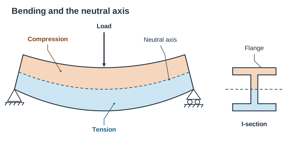
When a solid horizontal beam supported at both ends bends under a downward load, the top surface is squashed (compression) and the bottom surface is stretched (tension). Running through the middle is the neutral axis, a plane along which the material undergoes zero stretching and zero squashing.
Because stresses are concentrated at the extreme upper and lower edges, solid bars waste material near the neutral axis. Profiled sections, such as I-beams (universal beams) and hollow box sections, move material away from the central neutral axis to the outer flanges. This arrangement maximises bending stiffness while dramatically lowering the overall mass.
Justifying a Material Choice for a Structure
When asked to name a material for part of a structure and outline a property, always give a property that explains why it suits that member's specific loading:
- Tensile strength: Resists being pulled apart; essential in ties, cables, and sails.
- Compressive strength: Resists being crushed; essential in columns and struts.
- Strength-to-weight ratio: High strength for low mass; essential in masts, bicycle frames, and aircraft parts.
- Stiffness (rigidity): Resists bending under load; essential in beams and machine frames.
- Toughness: Absorbs impact energy without fracturing; essential in helmets and vehicle bumpers.
- Ductility: Can be drawn into wire or plastically deformed without breaking.
- Hardness: Resists scratching, denting, and wear; essential at bearing and cam surfaces.
- Corrosion resistance: Resists rusting or chemical attack; essential outdoors and in marine environments.
Model response: A boat mast is made from aluminium alloy because it has a high strength-to-weight ratio, ensuring the mast is strong enough to carry rigging loads without making the boat top-heavy.
Forces in Structures, Triangulation, and Stability
External forces acting on structures are classified by their behaviour:
- Static (dead) loads: Permanent, stationary forces that do not move, including the structure's own self-weight and fixed machinery.
- Dynamic (live) loads: Forces that vary in magnitude, position, and direction over time, including pedestrians, moving traffic, wind gusts, and snow accumulation.
Every structure experiences five primary internal forces that you must recognise and describe:
- Tension: A pulling or stretching action that tends to elongate a member. A structural component under tension is called a tie (e.g. crane tie cables, bicycle spokes, suspension bridge hangers).
- Compression: A squashing or pushing action that tends to shorten a member. A component under compression is called a strut (e.g. building columns, chair legs, scaffold verticals). Slender struts are susceptible to buckling (sudden sideways deformation and failure), which requires them to have stiffer or thicker cross-sections than ties.
- Shear: Opposing, offset forces acting across a material that attempt to slide adjacent layers past one another (e.g. joint pins, bolts under transverse loads, shear pins in marine propellers).
- Torsion: A twisting action caused by opposing turning forces about a member's longitudinal axis (e.g. car drive shafts, screwdriver shanks, drill bits).
- Bending: A combined force condition where transverse loading induces compression on the concave surface and tension on the convex surface, separated by the neutral axis.
The Member Removal Test for Struts and Ties
To identify whether an internal member in a pin-jointed truss is a strut or a tie, apply the member removal test:
- Mentally remove the member in question while keeping external loads applied.
- If the two connecting joints tend to move apart, the member was holding them together: it is in tension and functions as a tie.
- If the two connecting joints tend to move closer together, the member was holding them apart: it is in compression and functions as a strut.
Ties can be made from slender cables, chains, or thin rods because tensile forces pull members straight, eliminating the risk of buckling. Struts must be rigid tubes or profiled sections to resist buckling.
Triangulation and Structural Bracing
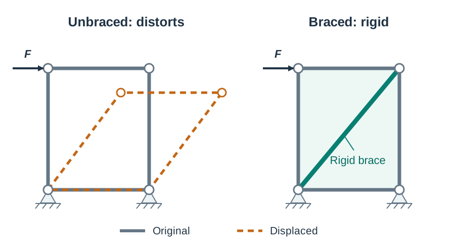
A four-sided rectangular pin-jointed frame is inherently unstable; lateral loads easily deform it into a parallelogram without altering member lengths. In contrast, a triangle cannot change its geometric shape without altering the physical length of at least one of its sides. Triangulation is the technique of inserting diagonal bracing members across open frames to divide them into interconnected triangles, providing rigidity and resistance against shear and wind distortion.
Centre of Gravity and Equilibrium
The centre of gravity (CG) is the unique point at which the entire weight of an object can be considered to act. For a structure to remain balanced and in static equilibrium, two conditions must hold simultaneously:
- The forces must balance: total upward force = total downward force, and total force to the left = total force to the right.
- Resultant turning effects must be zero (Principle of Moments): total clockwise moments = total anticlockwise moments.
Finding the Centre of Gravity (Plumb-Line Method)
To find the centre of gravity of an irregular flat shape (lamina):
- Pierce a small hole near the edge of the shape and hang it freely from a pin. A freely suspended body always settles with its centre of gravity directly below the point of suspension.
- Hang a plumb line (a thread with a small weight) from the same pin to mark a true vertical line.
- Draw the line of the thread onto the shape. The centre of gravity lies somewhere along this line.
- Repeat the procedure from a second, well-separated hole and draw a second line.
- The point where the two lines intersect is the centre of gravity. A third hole can be used as an independent check.
Three States of Equilibrium
- Stable equilibrium: If the body is tilted slightly, its centre of gravity rises and it returns to its original resting position (e.g. a cone resting on its broad base, a traffic cone).
- Unstable equilibrium: A small tilt lowers the centre of gravity and the body topples further away from its initial position (e.g. a cone balanced on its pointed apex).
- Neutral equilibrium: The centre of gravity stays at the exact same height when the body is moved, so it remains at rest wherever it is placed (e.g. a sphere or cylinder resting on a flat, horizontal table).
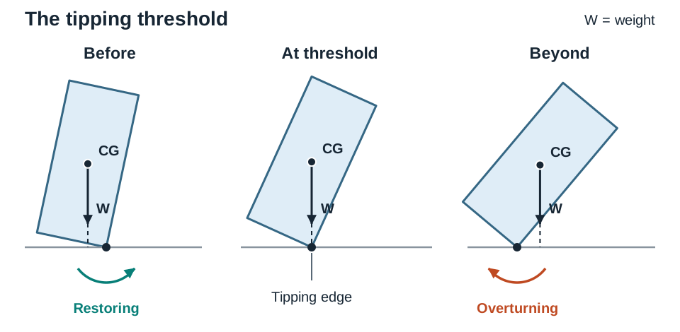
The Critical Toppling Condition: A freestanding structure will topple whenever the vertical line of action drawn downwards from its centre of gravity falls outside the perimeter of its base of support. You can maximise stability in any design by lowering the centre of gravity (placing heavy items like drive motors and batteries near the bottom) and widening the base of support (using outriggers, splayed legs, or wide base plates).
Factor of Safety and Structural Testing
Design calculations rely on idealised figures, but real structures face unexpected situations. Designers build in a margin of safety using the factor of safety:
The factor of safety is a pure ratio with no units. Common reasons for incorporating an appropriate factor of safety include:
- Overloading: Extra loads exceeding routine design specifications.
- Material imperfections: Undetected microscopic cracks, air voids, or grain inconsistencies.
- Environmental degradation: Gradual loss of cross-sectional area through corrosion, weathering, or fatigue.
- Calculation approximations: Simplifying assumptions used in mathematical models of dynamic shock loads.
Critical applications where failure could cause injury or loss of life (e.g. passenger lifts, overhead cranes, aircraft airframes) require high factors of safety (typically 4 to 10). Non-critical, low-risk consumer products use lower factors (e.g. 1.5 to 2) to avoid unnecessary weight, material consumption, and manufacturing expense.
Testing Structures: Destructive vs Non-Destructive
Engineers verify material properties and structural performance through two complementary testing philosophies:
- Destructive testing: The test specimen is loaded progressively until it yields, deforms permanently, or fractures completely (e.g. tensile testing of a metal specimen in a tensometer to plot stress-strain curves, or drop-impact testing of prototype helmets). This establishes the actual breaking load and failure mode, but leaves the tested part unusable.
- Non-destructive testing (NDT): Inspects materials and components for internal flaws or surface cracks without causing damage or impairing their future serviceability. Crucial for items in active service, common NDT methods include:
- Visual inspection: Direct examination for distortion, paint cracking, and surface rusting.
- Dye penetrant testing: A coloured or fluorescent liquid penetrant is applied to cleaned metal surfaces; after wiping off excess liquid, developer draws trapped dye out of minute surface cracks, highlighting defects under visible or UV light.
- Ultrasonic testing: High-frequency sound waves are pulsed into a material; internal voids, fissures, or inclusions reflect waves back to a transducer earlier than the rear wall echo.
- X-ray radiography: Penetrating radiation passes through welded seams onto photographic film or digital detectors, revealing hidden internal gas pockets and slag inclusions.
Testing a Model Frame Structure Step-by-Step
A common exam question asks you to describe an experiment comparing a braced and an unbraced frame. Lay it out as ordered steps with reasons:
- Build two identical square frames from the same material and section (e.g. 6 mm square softwood) using identical corner joints, ensuring the only difference is the bracing.
- Add a single diagonal brace to one frame only. This serves as the independent variable.
- Clamp each frame securely to the workbench in the same manner to ensure identical support conditions.
- Apply a horizontal load at the top corner in equal increments (e.g. 5 N at a time) using a spring balance or slotted masses.
- Measure the sideways deflection at the loaded corner after each increment using a rule or dial gauge, recording results in a table.
- Plot load against deflection for both frames on the same axes.
- Conclusion: The unbraced frame deforms into a parallelogram under a light load, while the triangulated frame deflects far less under the same load, proving that triangulation provides rigidity.
Controlled variables: Span, material, member cross-section, joint type, position and direction of applied load.
Motion Types, Levers, and Linkages
Mechanisms transmit or transform movement, force, and torque between inputs and outputs. Mechanical motion is grouped into four fundamental types:
- Linear motion: Travel along a straight path in a single direction (e.g. a lift carriage rising).
- Reciprocating motion: Continuous back-and-forth movement in a straight line (e.g. an engine piston, a sewing machine needle).
- Rotary motion: Movement following a circular path around a central pivot or axis (e.g. an electric motor spindle, a bicycle wheel).
- Oscillating motion: Swinging back and forth along a curved circular arc about a pivot (e.g. a clock pendulum, a playground swing).
Levers and the F-L-E Classification
A lever is a rigid beam rotating about a fixed pivot (fulcrum) to overcome a resisting load using an applied effort. Levers are classified by which component sits in the middle:
- First Order (Fulcrum in the middle): See-saws, crowbars, scissors, claw hammers. Reverses the direction of motion. Mechanical advantage can be greater than, equal to, or less than 1 depending on pivot placement.
- Second Order (Load in the middle): Wheelbarrows, nutcrackers, bottle openers. The effort arm is always longer than the load arm. Mechanical advantage is always greater than 1, meaning output force exceeds input effort.
- Third Order (Effort in the middle): Tweezers, fishing rods, the human forearm. Mechanical advantage is always less than 1, trading force to gain greater speed and movement distance at the load.
Numerical lever example: A wheelbarrow (second order) carries a 700 N load located 0.4 m from the wheel axle. The handles are gripped 1.4 m from the axle. Applying moments about the axle:
Linkages
A linkage is an assembly of connected rigid levers used to transfer motion, change its direction, or coordinate simultaneous movements:
- Reverse-motion linkage: Uses a central fixed pivot with equal lever arms to turn an upward input directly into an equivalent downward output.
- Bell-crank linkage: An angled lever (commonly 90°) pivoted at its vertex that redirects movement around corners (e.g. bicycle brake callipers).
- Parallel-motion linkage: Employs a parallelogram arrangement of equal opposing links to ensure an output platform remains parallel to its base throughout travel (e.g. adjustable desk lamps, cantilever toolboxes).
- Crank and slider: Converts continuous rotary motion into reciprocating linear motion, or vice versa (e.g. car engine crankshaft and connecting rod).
Gears and Rotary Transmissions
Gears transmit rotary motion between shafts while modifying rotational speed (RPM) and torque.
Spur Gears and Gear Trains
When two spur gears mesh directly, their teeth engage along their pitch circles and they always rotate in opposite directions. The speed and tooth relationship is defined by the gear ratio:
- Idler gears: An intermediate gear placed between a driver and driven gear changes the direction of rotation and bridges centre distance. An idler does not change the overall gear ratio or output speed because its tooth count cancels out during calculations.
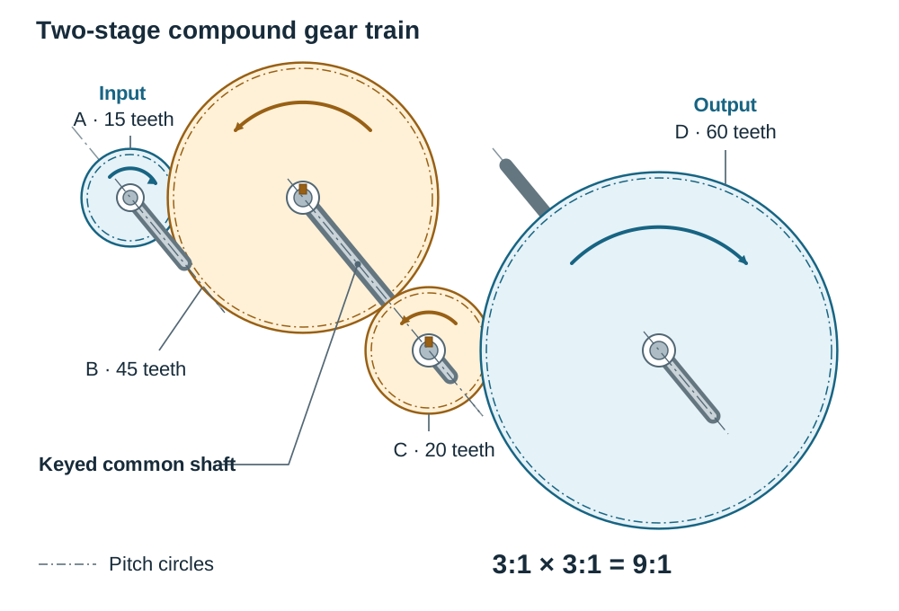
- Compound gear trains: Two or more gears are keyed to the same intermediate shaft, rotating together at identical speeds. Compound trains provide large overall speed reductions within compact physical footprints without needing massive individual gears. To find the total gear ratio, multiply the individual stage ratios:
Speed Down, Turning Force Up
Any gear train or belt drive trades speed against turning force. A reduction drive (large driven gear, small driver) lowers output speed and increases output torque in the same proportion; an overdrive (small driven gear, large driver) does the opposite.
For a 9:1 reduction driven by a motor producing 2 Nm:
- Output speed = input speed ÷ 9
- Output torque ≈ input torque × 9 = 18 Nm (slightly less in practice due to friction)
This explains why a small, fast, low-torque electric motor can lift a heavy load in a hoist or turn a slow-moving beater in a food mixer. Energy is conserved: the output shaft turns nine times more slowly, so the same mechanical work is distributed over fewer rotations per minute.
Specialised Gear Types
| Gear Type | Shaft Arrangement | Operation and Characteristics | Practical Application |
|---|---|---|---|
| Helical gears | Parallel shafts | Curved, angled teeth mesh gradually; quieter, smoother, and handles higher loads than spur gears | Car manual gearboxes |
| Bevel gears | Intersecting shafts (usually 90°) | Conical gears with angled teeth to redirect drive around corners | Hand drills, rear-axle differentials |
| Worm and wheel | Perpendicular, non-intersecting shafts | Screw-threaded shaft (worm, 1 tooth) meshes with toothed wheel; massive speed reduction in one step; self-locking | Lifting hoists, winches, conveyors |
| Rack and pinion | Rotary shaft to linear track | Circular gear (pinion) meshes with flat toothed bar (rack); converts rotary motion directly to linear motion | Car steering racks, drill press feeds |
The self-locking feature of the worm and wheel is a crucial safety mechanism: the worm can drive the wheel, but torque applied to the wheel cannot turn the worm backwards because of high tooth friction and shallow lead angles. This prevents suspended loads from falling if drive power is cut.
Pulleys, Belt Drives, Lead Screws, and Cams
Pulleys: Lifting Systems vs Rotary Belt Drives
Pulleys operate in two distinct functional roles:
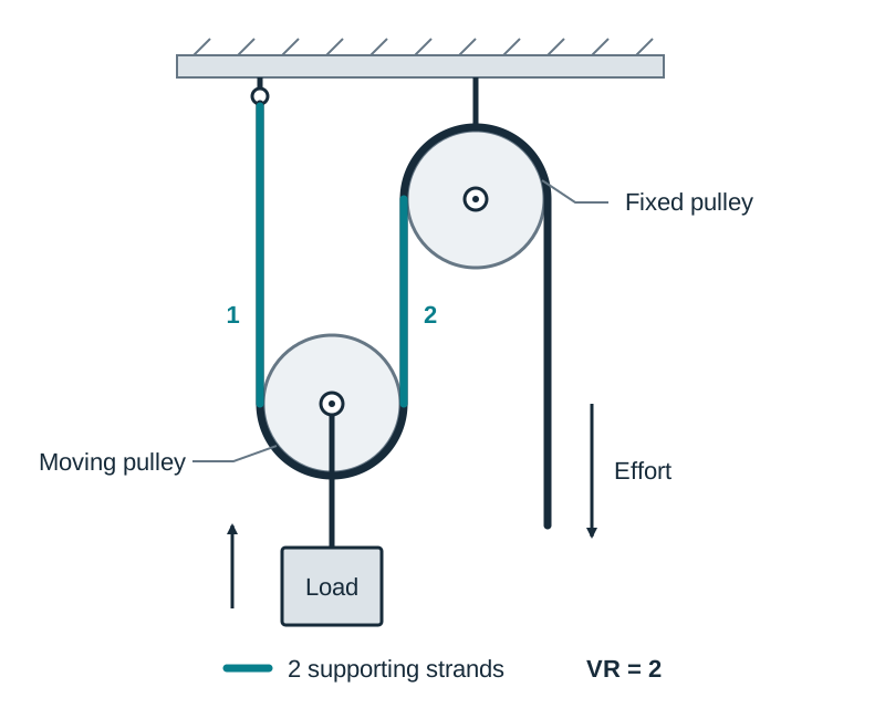
- Lifting pulleys (block and tackle): A single fixed pulley changes only the direction of the applied effort (). A compound pulley system combines fixed and moving blocks where multiple rope strands support the moving load. The velocity ratio equals the number of rope strands directly supporting the load block.
- Rotary belt drives: Flexible belts transfer drive between separated shafts:
- Belt drive types:
- Flat belts: Simple and quiet; prone to slip under excessive loads.
- V-belts: The trapezoidal wedge shape wedges tightly into matched pulley grooves, generating high frictional grip and reducing slip (e.g. pillar drills, vehicle alternators).
- Toothed (timing) belts: Rubber belts with internal teeth that mesh positively with toothed pulleys, providing non-slip synchronisation (e.g. engine camshaft drives, 3D printer axis control).
- Crossed belts: Belts crossed into a figure of eight to reverse the rotational direction of the driven shaft.
Chain and Sprocket Drive
A roller chain runs over toothed wheels called sprockets. Because the chain teeth engage positively with the sprocket teeth, there is no slip, ensuring input and output shafts remain synchronised (e.g. bicycle transmissions, motorcycle final drives, industrial conveyor drives).
Both sprockets rotate in the same direction.
| Feature | Belt Drive | Chain Drive |
|---|---|---|
| Slip | Can slip (acts as an overload safety release) | No slip — positive mechanical drive |
| Load capacity | Lighter to medium loads | Heavy loads and high torque |
| Noise | Quiet operation | Noisier due to metal-on-metal engagement |
| Maintenance | Minimal; inspect belt tension and wear | Requires regular lubrication and chain tensioning |
Lead Screw (Screw and Nut)
A threaded shaft turns inside a captive nut. One full rotation of the screw advances the nut along the shaft by one pitch (the distance between adjacent thread peaks). It converts rotary motion into slow, powerful, highly controllable linear motion and is normally self-locking (e.g. bench vices, G-clamps, scissor jacks, 3D printer Z-axis leadscrews).
For example, a screw with a 2 mm pitch turned 15 complete revolutions moves the nut: .
Cam and Follower Mechanisms
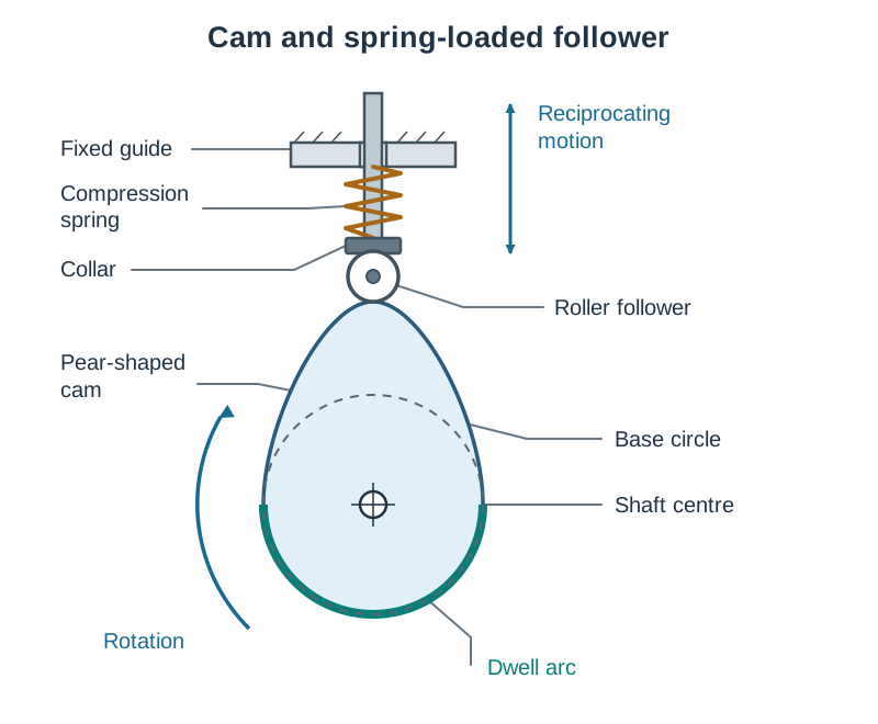
A cam is a profiled rotating disc that converts continuous rotary motion into precise reciprocating or oscillating motion via a follower. A spring is regularly used to ensure continuous contact between the follower and the rotating cam profile.
- Cam profiles:
- Pear-shaped: Provides a defined dwell period at minimum lift, followed by a rapid rise and fall (used for internal combustion engine valves).
- Eccentric (circular): A circular disc mounted off-centre from its shaft, producing smooth, continuous harmonic reciprocating motion.
- Heart-shaped (constant velocity): The follower rises and falls at a uniform, constant velocity and has no dwell — it remains in continuous motion (e.g. winding thread evenly onto a sewing bobbin).
- Cam terminology:
- Base circle: The smallest circle drawn tangent to the cam profile, on which the follower dwells.
- Lift (stroke): The maximum displacement of the follower, calculated as: . For example, a cam with a maximum radius of 40 mm and a base circle radius of 25 mm provides a lift of .
- Follower types:
- Knife-edge: Highly accurate tracking of intricate profiles, but rapid point wear due to high contact pressure.
- Flat: Spreads contact loads over a wider area; experiences significant sliding friction.
- Roller: Features a rolling wheel or needle bearing that replaces sliding friction with rolling friction, substantially lowering component wear and heat generation at high operating speeds.
- Phases of motion: Rise (follower travels outward/upward as cam radius increases), Fall (follower returns as radius decreases), and Dwell (follower remains stationary while riding along a constant-radius segment).
Mechanical Principles: Work, Power, Friction, and Efficiency
Moments and Torque
The moment of a force is its turning effect about a pivot:
Force is in newtons (N), distance is in metres (m), and moment is in newton metres (Nm). Torque () represents turning effect about an axis (such as an engine drive shaft), also measured in Nm.
Torque calculation with metric unit conversion: A technician tightens a cylinder head bolt to a specified torque of 42 Nm using a torque wrench. If the technician pushes perpendicularly on the handle at a point located 350 mm from the centre of the bolt, calculate the required input force in newtons.
- State formula:
- Convert distance to metres:
- Calculate force:
Work and Power
- Work: Done only when an applied force displaces an object in the direction of the force:
One joule equals one newton metre (). If an applied force produces no displacement, zero work is performed.
- Power: The rate of doing work or transferring energy:
One watt equals one joule per second (). Electrical power is calculated as .
Friction, Bearings, and Lubrication
Friction is the resisting force opposing relative motion between contacting surfaces. Friction is useful in tyre grip, brake pads, and belt-drive traction, but wasteful in bearings and gear meshes where it dissipates energy as heat, accelerates wear, and reduces machine efficiency.
Engineers minimise wasteful friction by:
- Lubrication: Introducing an oil or grease film that physically separates sliding metal faces. Enclosed industrial gearboxes use an oil-bath lubrication system where liquid oil sits in the lower casing reservoir. As the lowest gears rotate, they dip into the bath and splash a continuous oil film across meshing teeth and shaft bearings.
- Bearings: Ball and roller bearings replace sliding contact with rolling contact, significantly reducing friction.
Mechanical Advantage, Velocity Ratio, and Efficiency
- Mechanical Advantage (MA): Force multiplication achieved by a machine:
- Velocity Ratio (VR): Distance movement ratio determined strictly by geometry:
- Efficiency (): The percentage of input energy or power converted into useful output:
For a simple machine (such as a lever or pulley hoist), efficiency can also be calculated as:
Because friction dissipates part of the input energy as heat, the actual mechanical advantage is always less than the velocity ratio in real machines. No real machine operates at 100% efficiency.
Official Relationships and Formulas Summary
You do not need to derive these relationships in the examination; you only need to select the correct formula, substitute values with consistent units, and calculate the result:
Key terms
- Frame Structure
- A skeletal structure composed of joined members (struts and ties) with open spaces, supporting loads efficiently along lines of force.
- Shell Structure
- A hollow structure where a thin, curved outer skin carries loads across its surface without internal framing.
- Box Structure
- A hollow, closed structural section (such as a square tube or box girder) offering high resistance to bending and torsional twisting.
- Strut
- A structural member subjected to axial compressive forces, which is prone to sudden failure by buckling if slender.
- Tie
- A structural member subjected to axial tensile forces pulling it straight, which cannot fail by buckling.
- Triangulation
- The technique of arranging structural members into interconnected triangles to produce a rigid frame that cannot deform without altering member lengths.
- Centre of Gravity
- The unique point in a body through which its entire weight can be considered to act.
- Moment of a Force
- The turning effect of a force about a pivot point, calculated as force multiplied by perpendicular distance to the fulcrum, measured in Nm.
- Factor of Safety
- The ratio of ultimate failure load (or breaking strength) to the maximum expected working load, providing an essential margin against failure.
- Non-Destructive Testing (NDT)
- Inspection methods (such as ultrasonic, X-ray, dye penetrant, or visual testing) that detect internal or surface flaws without damaging the part.
- Idler Gear
- An intermediate gear placed between a driving and driven gear that alters output rotation direction without changing the overall gear ratio.
- Worm and Wheel
- A mechanism featuring a threaded worm screw driving a toothed gearwheel, offering high single-stage speed reduction and an inherent self-locking safety feature.
- Dwell
- The phase during cam rotation where the profile radius remains constant, causing the follower to stay completely stationary.
- Mechanical Advantage
- The ratio of load force overcome to applied effort force (Load ÷ Effort), having no units.
- Velocity Ratio
- The ratio of distance moved by the effort to distance moved by the load, determined entirely by machine geometry.
- Efficiency
- The percentage of input energy or power converted into useful output. Efficiency (%) = (power output ÷ power input) × 100, which equals (MA ÷ VR) × 100 for simple machines.
Check yourself
What structural function distinguishes a box structure from an open flat plate of identical mass?
A box structure forms a closed hollow section that positions material far from the neutral axis, providing significantly higher resistance to bending deflection and torsional twisting.
Under what condition does a freestanding structure topple over?
A structure topples when the vertical line of action passing through its centre of gravity falls outside the perimeter of its base of support.
State the two conditions required for a structure to remain in static equilibrium.
The resultant linear forces in all directions must balance (total upward force equals total downward force, and lateral forces balance), and total clockwise moments must equal total anticlockwise moments about any pivot.
Why is a worm and wheel mechanism self-locking, and where is this safety property used?
The worm screw can drive the toothed wheel, but the wheel cannot drive the worm backwards due to tooth friction and shallow thread angle. This is used in hoists and cranes to prevent suspended loads from falling if drive power is lost.
What is the mechanical advantage of a second-order lever, and why?
The mechanical advantage is always greater than 1 because the load sits between the fulcrum and the effort, meaning the effort arm is always longer than the load arm.
Why are roller followers preferred over knife-edge followers in high-speed cam mechanisms?
Roller followers replace sliding friction with rolling contact, significantly reducing friction, heat generation, and component wear.
How does an oil-bath lubrication system operate in an enclosed gearbox?
The lower casing forms a reservoir of lubricating oil. As the lower gears rotate, they dip into the bath and splash oil continuously over meshing gear teeth and shaft bearings.
A structural tie rod fails at a tensile load of 36 kN and has an operational working load of 9 kN. Calculate its factor of safety.
Factor of Safety = Failure Load ÷ Working Load = 36 kN ÷ 9 kN = 4 (no units).