
Electricity supplies the energy that powers modern technological systems, while electronics controls the path, timing, and form that this energy takes. In Leaving Certificate Higher Level Technology, this topic spans fundamental energy sources and transformations, power costs, core circuit calculations (Ohm's Law, power dissipation, and resistor networks), sensor-interfaced potential dividers, transistor switching, output interfacing, and digital logic. Under the adjusted 2027 assessment arrangements, the written examination accounts for 50% of the total marks, and the coursework project accounts for the remaining 50% (due 19 March 2027). The Higher Level written paper lasts 2½ hours: Section A (answer 12 of 15 short questions) and Section B (answer two long core questions) remain unchanged, while in Section C you answer one of the five option questions. Even though you answer one option question in Section C, you study two options throughout Senior Cycle, allowing you to choose the question that best suits your strengths on the day. Your coursework brief requires a working model with an electro-mechanical element operating from a safe, low-voltage supply.
Energy Sources, Forms, Transformations, and Power Costs
Every technological artefact relies on converting energy from one form to another. Energy sources fall into two broad groups:
- Renewable sources: Naturally replenished on a continuous basis and will not run out. These include wind, solar (photovoltaic and solar thermal), hydroelectric, wave, tidal, biomass, and geothermal. They generate minimal greenhouse gas emissions during operation, although sources like wind and solar are intermittent and depend on weather conditions.
- Non-renewable sources: Finite reserves that deplete with use, including fossil fuels (coal, oil, and natural gas) and nuclear fission fuels (such as uranium). Burning fossil fuels releases carbon dioxide (), which accelerates climate change. Coal combustion also emits sulphur dioxide (), leading to acid rain. Nuclear fission provides reliable baseload power without greenhouse gas emissions during operation, but it produces long-lived radioactive waste that requires secure, long-term storage.
Forms of Energy and Device Transformations
You must be able to name and distinguish between seven common forms of energy: kinetic energy (motion, such as a spinning motor shaft), potential energy (stored energy due to position or strain, such as a raised counterweight or compressed spring), chemical energy (stored within battery reactants or fuels), electrical energy (carried by charge flowing through conductors), and thermal energy, light energy, and sound energy, which often appear as outputs or waste.
The Principle of Conservation of Energy states that energy cannot be created or destroyed; it can only change from one form into another. When energy is described as lost, it has not vanished. It has simply converted into an unusable form, almost always waste heat caused by electrical resistance and mechanical friction. When writing out energy chains in exams, always include these waste outputs:
- Torch: chemical (battery) electrical light + heat
- Electric kettle: electrical thermal (+ sound)
- Loudspeaker: electrical sound + heat
- Solar photovoltaic panel: light electrical
- Geared winch on a project artefact: chemical (battery) electrical kinetic (motor and gear train) potential energy (lifted load) + heat and sound
Efficiency and the Cost of Energy
Efficiency expresses the proportion of input energy or power that is converted into useful work:
No real machine achieves efficiency because of resistive heating and friction.
Electricity meters record commercial energy consumption in kilowatt-hours (kWh), commonly called units of electricity. One kilowatt-hour is the energy consumed by a appliance operating continuously for one hour ():
Worked Example: Cost of Energy
An immersion heater rated at runs for each day. Electricity costs per unit. Calculate the running cost for .
- Convert time to hours: .
- Energy used per day: .
- Total energy over 30 days: (67.5 units).
- Total cost: , which rounds to €23.63.
Always ensure power is in kilowatts () and time is in hours before multiplying.
Electrical Fundamentals, Ohm's Law, Power, and Safe Supplies
A circuit requires an unbroken conducting loop from the positive terminal of a power source, through the load, and back to the or negative return. Breaking this path stops current flow instantly.
Three quantities describe what is happening in any circuit:
- Current (): The rate of flow of electric charge, measured in amperes or amps (A). Conventional current flows from positive to negative.
- Voltage (): The electrical push or potential difference between two points, measured in volts (V). One volt equals one joule of energy per coulomb of charge ().
- Resistance (): The opposition offered to current flow, measured in ohms ().
Think of a water pipe: voltage is the pump pressure forcing water through, current is the volume of water moving past each second, and resistance is a narrow constriction restricting the flow.
Ohm's Law and Prefixes
Ohm's Law states that the current through an ohmic conductor is directly proportional to the potential difference across it at constant temperature:
Always convert prefixed numbers into base SI units before substituting into equations:
- Mega (M): ()
- Kilo (k): ()
- Milli (m): ()
- Micro (µ): ()
- Nano (n): ()
A useful calculation shortcut is that volts, milliamperes, and kilohms balance naturally without powers of ten: .
Electrical Power
Electrical power () is the rate at which electrical energy is transformed into other energy forms, measured in watts (W), where :
Every component has a maximum power rating (often for standard carbon film resistors). If power dissipation exceeds this rating, the resistor overheats and burns out.
Power Supplies and Electrical Safety
For school project work, power must always come from a safe low-voltage supply ( or lower); never connect a student artefact directly to mains.
- Batteries: Provide portable, ripple-free direct current. Connect cells in series to increase voltage () or in parallel to increase current capacity (mAh).
- Regulated power supply: Mains-powered bench unit that steps down, rectifies, and regulates voltage. A fixed regulator IC (such as a 7805) provides the steady voltage rail required by digital logic ICs.
- Circuit protection devices: A fuse or miniature circuit breaker (MCB) contains an element calibrated to melt or trip when current exceeds a set threshold, protecting cables against fire. A residual current device (RCD) monitors the balance between live and neutral currents and cuts power within milliseconds if current leaks to earth through a user.
- Workshop safety: Always isolate supplies before altering wiring, maintain soldering irons in proper stands, provide adequate ventilation for flux fumes, wear eye protection when trimming component leads, and treat chemical etchants with gloves and goggles.
Resistor Networks, Colour Codes, Multimeters, and Current Types
Resistor Colour Code
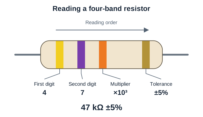
Most resistors use four coloured bands. The first three bands give the resistance value and the fourth gives the tolerance (how far the true value may deviate from the stated value):
- Band 1: First significant digit
- Band 2: Second significant digit
- Band 3 (Multiplier): Number of zeros to append ()
- Band 4 (Tolerance): Gold = , Silver =
The colour sequence follows: Black (0), Brown (1), Red (2), Orange (3), Yellow (4), Green (5), Blue (6), Violet (7), Grey (8), White (9). Use the mnemonic: Bad Boys Race Our Young Girls But Violet Generally Wins.
For example, Yellow-Violet-Orange-Gold represents , , and zeros: .
Series and Parallel Resistor Networks
- Resistors in series: Connected in a single line. The same current flows through each resistor, while supply voltage divides across them:
- Resistors in parallel: Connected across common nodes. The full supply voltage appears across every branch, while the total supply current splits:
The equivalent resistance of a parallel pair is always strictly less than the smallest individual branch resistance.
Digital Multimeter Measurements
- Voltmeter: Measures potential difference. Connect in parallel across the component. A voltmeter has an extremely high internal resistance, so it draws virtually no current and does not disturb the circuit.
- Ammeter: Measures current flow. Break the circuit path and insert the ammeter in series, observing polarity. An ammeter has a very low internal resistance to avoid opposing current flow.
- Ohmmeter: Measures resistance. The component must be tested with circuit power disconnected. Furthermore, you must disconnect at least one leg of the component from the board; otherwise, alternative parallel circuit paths cause the meter to read a false, lower resistance value.
Direct Current (D.C.) vs Alternating Current (A.C.)
- Direct Current (D.C.): Charge carriers flow in one unchanging direction around the circuit. Chemical cells, batteries, and regulated d.c. adapters produce D.C., which is required by transistors and digital integrated circuits.
- Alternating Current (A.C.): Current continuously reverses direction at a set frequency (), measured in hertz (Hz). Irish mains electricity is at , meaning it completes 50 full cycles (100 directional reversals) every second. Mains distribution relies on A.C. because transformers can step voltages up to high levels for long-distance grid transmission, reducing transmission current and minimising cable power losses ().
Signals, Circuit Symbols, and Input-Process-Output Systems
Analogue versus Digital Signals
Electronic signals transfer information through voltage changes:
- Analogue signal: A voltage that varies smoothly and continuously, taking any intermediate value between its minimum and maximum limits. When plotted on a graph, it appears as a continuous, curved wave. Analogue components include light-dependent resistors (LDRs), thermistors, moisture sensors, potentiometers, microphones (acting as sound sensors), and loudspeakers.
- Digital signal: A voltage restricted to two discrete levels: Logic 1 (HIGH, typically ) and Logic 0 (LOW, ). On a graph, it forms a square wave with vertical transitions and flat levels. Digital components include push switches, microswitches, logic gates, microcontrollers, and counter ICs.
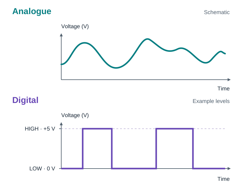
Because analogue sensors output continuously varying voltages while digital processing chips require sharp HIGH/LOW inputs, interface circuits such as potential dividers, transistor switches, Schmitt triggers, or analogue-to-digital converters (ADCs) must sit between them.
Input Switches and Circuit Symbols
Standard input switches include:
- Push-to-make (PTM): Normally open; completes the circuit only while held down (e.g. doorbell or reset switch).
- Push-to-break (PTB): Normally closed; breaks current path while pressed (e.g. refrigerator door sensor).
- SPST toggle/slide: Simple single-pole single-throw on-off switch.
- SPDT: Single-pole double-throw switch that directs current to one of two paths.
- DPDT: Double-pole double-throw switch; six terminals arranged to switch two lines simultaneously, commonly used for motor reversal.
- Microswitch: Sensitive snap-action switch triggered by small physical movements, used as a limit switch in mechanisms.
- Reed switch: Sealed magnetic switch closed by the proximity of an external magnet, ideal for non-contact door alarms.
You must be able to recognise and draw standard circuit symbols: d.c. cell and battery, fixed resistor, variable resistor/potentiometer, LDR, thermistor, capacitor, electrolytic capacitor, diode, LED, lamp, NPN transistor, relay coil and switch contacts, fuse, buzzer, d.c. motor, logic gates, and the ground rail.
The Systems Approach
Every electronic solution can be structured into three stages:
Drawing this block diagram first and naming the components inside each block (e.g. Thermistor Potential Divider & Transistor Relay & Geared Motor) ensures your circuit explanation follows a logical structure.
Potential Dividers, Sensor Interfacing, and Transistor Switching
The Potential Divider
A potential divider consists of two resistors in series across a supply voltage (). It divides the supply voltage in direct proportion to their resistance values, delivering an intermediate output voltage () at their shared junction:
where is the bottom component connected between the output node and the rail. The larger resistor always drops the larger share of the voltage.
Worked Example: Potential Divider Switching Threshold
A supply feeds a divider comprising a fixed resistor at the top () and an LDR at the bottom (). In bright light the LDR resistance is ; in darkness it rises to . Calculate under both conditions:
- In bright light ():
- In darkness ():
Replacing the fixed resistor with a variable resistor allows you to calibrate the switching threshold by hand so the circuit triggers at the desired light level.
Sensor Characteristics and Graphical Curves
- Light-Dependent Resistor (LDR): Cadmium sulphide sensor. In darkness its resistance is high (); in bright light its resistance falls to a few hundred ohms.
- Negative Temperature Coefficient (NTC) Thermistor: Resistance decreases non-linearly as temperature rises. When examining a thermistor characteristic curve (resistance vs temperature), look at the slope: a very steep section means high sensitivity but a narrow operating window, while a flat region means large temperature changes produce negligible resistance shifts. The effective range is the region with a moderate, steady slope.
- Moisture sensor: Two exposed conductive probes or tracks whose resistance falls sharply when water bridges them, used in rain detectors, plant-watering alarms and leak alarms. Like the LDR and thermistor, it is wired as one arm of a potential divider so that its resistance change becomes a voltage change at the junction.
Transistor Switching Operation
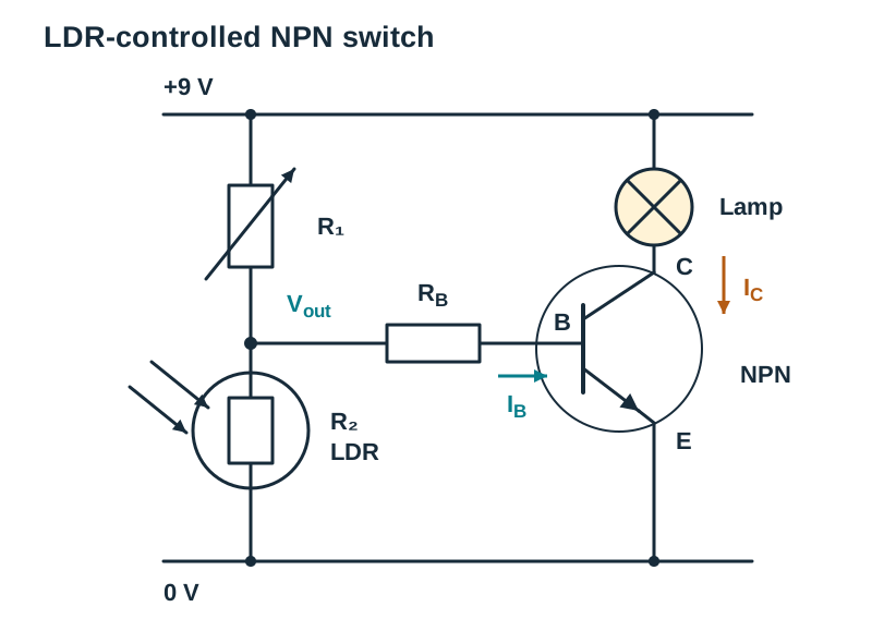
An NPN bipolar junction transistor acts as an electronic switch. It has three terminals: base (B), collector (C), and emitter (E). It requires a base resistor to limit current and prevent thermal destruction.
When writing a full-mark circuit explanation in continuous prose, use this exact sequence: "As darkness falls, the resistance of the LDR increases. Because the LDR is in the lower position () of the potential divider, it takes a larger share of the supply, causing the junction voltage to rise. When this base voltage reaches approximately (values between and are characteristic of silicon transistors) and base current flows, the transistor switches fully ON into saturation. Collector current then flows freely through the output device connected in the collector branch, energising the load."
Making Circuits More Responsive
If a sensor circuit does not trigger crisply, three modifications earn marks:
- Adjust the variable resistor in the divider to shift the baseline voltage closer to .
- Use a Darlington pair: two transistors connected so the emitter of the first feeds the base of the second. The overall current gain equals the product of their individual gains (), allowing a tiny sensor current to switch a heavy load (switching threshold becomes ).
- Replace the single transistor with an operational amplifier voltage comparator.
Output Devices, Capacitors, and Driver Circuits
Output Devices
- Lamps (filament bulbs): A thin filament heats until it glows, giving light plus a lot of waste heat. A lamp draws far more current than an LED, so it is usually switched by a transistor or relay rather than driven directly from a sensor circuit.
- Light Emitting Diodes (LEDs): Highly efficient semiconductor lamps. An LED is polarised: the longer leg is the anode (+), and the shorter leg beside the flat rim on the plastic body is the cathode (−). An LED must always have a series resistor to drop the surplus supply voltage and limit forward current to safe levels (usually ).
- Buzzers and Speakers: Buzzers produce a fixed warning tone from steady D.C.; loudspeakers convert alternating analogue waveforms into audible sound.
- Relays: Electromechanical switches consisting of a wire coil wound on an iron core and moving contacts. When energised, the coil becomes an electromagnet that pulls contacts closed, allowing a sensitive or control circuit to safely switch a separate high-current or mains circuit with total electrical isolation.
- D.C. Motors: Convert electrical energy into rotary kinetic motion. When current is switched off, the motor's collapsing magnetic field creates a high-voltage reverse spike (back EMF).
Flyback / Free-Wheeling Diode
Inductive loads (relay coils, solenoids, and d.c. motors) store energy in an electromagnetic field. When the switching transistor turns OFF, this field collapses abruptly, inducing a damaging high-voltage reverse spike (back EMF). A flyback diode connected in reverse-bias across the coil clamps this spike safely, protecting the transistor from breakdown.
Capacitors in Circuits
A capacitor stores electric charge. Capacitance () is measured in farads (F), with microfarads (µF), nanofarads (nF), and picofarads (pF) used in practice.
- Non-polarised (ceramic, polyester): Small capacitance values; can be connected either way round.
- Electrolytic: High capacitance values; polarised. The negative terminal is marked with a stripe and minus sign and must connect to the lower voltage rail. Connecting an electrolytic capacitor backwards can cause it to overheat and burst.
- Functions: Used with a resistor to create a time delay (the capacitor charges through the resistor, causing the junction voltage to rise slowly over time), for smoothing d.c. power rails by reducing voltage ripple, and for decoupling IC power pins to absorb electrical noise.
Digital Logic Gates and Control Systems
Digital logic circuits make automated decisions based on binary input conditions (1 = HIGH, 0 = LOW). The Core syllabus specifies three primary gates:
- NOT Gate (Inverter): One input, one output. Inverts the input signal: .
- AND Gate: Outputs 1 only when all inputs are simultaneously 1: .
- OR Gate: Outputs 1 when at least one input is 1: .
Core Truth Table Summary
| Input A | Input B | NOT A | AND () | OR () |
|---|---|---|---|---|
| 0 | 0 | 1 | 0 | 0 |
| 0 | 1 | 1 | 0 | 1 |
| 1 | 0 | 0 | 0 | 1 |
| 1 | 1 | 0 | 1 | 1 |
(Option note: NAND and NOR gates, the TTL and CMOS logic families, Schmitt trigger inputs, and counting circuits belong to Option: Electronics and Control — study them if that is one of your two chosen options.)
Circuit Construction, PCB Production, and Systematic Fault-Finding
Construction Methods
- Solderless breadboard: Best for initial design prototyping, component testing, and tuning sensitivity. Components push into sprung metal spring contacts without soldering.
- Stripboard (Veroboard): Copper tracks bonded to synthetic resin paper. Used to assemble semi-permanent, soldered working prototypes for early coursework testing.
- Printed Circuit Board (PCB): Permanent, custom-etched copper tracks on fibreglass. Offers superior mechanical strength, compact layout, and neat integration for final coursework presentation.
PCB Production: The Photo-Etch Method
Exams require describing PCB production as an ordered sequence of steps with the technical reason for each:
- Design schematic and artwork in CAD: Generates an accurate layout with correct track widths and component pad sizes, preventing short circuits.
- Print artwork on transparent film: Creates a dense UV photomask where black ink blocks light over tracks that will remain.
- Expose photosensitive board to UV light: UV light shining through the clear areas of the mask chemically alters the photoresist layer.
- Develop board in chemical developer: Dissolves the resist that the UV light reached, leaving the unexposed resist covering only the copper that will become the tracks.
- Etch in ferric chloride: The acid dissolves all exposed, unprotected copper, leaving behind the copper track layout.
- Wash, strip resist, and drill holes: Rinses chemical residue, strips the remaining resist with solvent to expose clean copper pads, and drills holes using a drill bit.
- Solder components: Fit low-profile components first (resistors, diodes), soldering with clean, shiny joints.
Prototype vs Batch Production: Single prototypes use photo-etching or CNC milling. Batch industrial manufacturing uses computer-controlled photolithography, multi-layer etching, solder masking, automated pick-and-place component insertion, and wave soldering for low unit costs.
Systematic 4-Step Fault-Finding Sequence
When a completed circuit fails to operate, follow these ordered diagnostic steps:
- Check the power supply: Use a DMM on D.C. volts to verify battery voltage under load, check battery snap contacts, and confirm the switch is on.
- Check component orientation and polarity: Visually verify polarised components against the circuit diagram: LED flat edge/cathode, diode silver band, electrolytic capacitor negative stripe, transistor leads (E-B-C), and IC orientation notches.
- Inspect connections and soldering: Check for loose jumper wires on breadboards, hairline track cracks, cold/dull solder joints, and solder bridges causing short circuits between adjacent tracks.
- Check voltages step by step: With power applied, use a voltmeter referenced to to probe along the signal path from input to output. Check that the potential divider junction voltage responds to sensor changes, confirm the transistor base reaches , and ensure the collector voltage drops close to when switched ON.
Option Content: Advanced Electronics and Control
For students preparing for Section C (Option: Electronics and Control), the syllabus covers several advanced control topics:
NAND and NOR Universal Gates
- NAND Gate: An AND gate followed by an inverter (). Output is 0 only when all inputs are 1.
- NOR Gate: An OR gate followed by an inverter (). Output is 1 only when all inputs are 0.
| Input A | Input B | NAND | NOR |
|---|---|---|---|
| 0 | 0 | 1 | 1 |
| 0 | 1 | 1 | 0 |
| 1 | 0 | 1 | 0 |
| 1 | 1 | 0 | 0 |
Logic Families and Schmitt Triggers
- TTL (Transistor-Transistor Logic, 74 series): Requires a strictly regulated supply. Draws higher current, switches rapidly, and unused inputs should be tied to high or low rails.
- CMOS (4000 series): Operates across a wide supply voltage range () and draws minimal power, making it ideal for battery-operated devices. It is sensitive to static electricity and unused inputs must never be left floating.
- Schmitt Trigger: A gate built with hysteresis (separate upper and lower switching thresholds). It converts slowly changing or noisy analogue waveforms from sensors into clean, sharp digital square waves, preventing output chatter.
Astable and Monostable Timing Circuits
- Astable multivibrator: Has no stable state; its output oscillates continuously between HIGH and LOW, generating a continuous square wave (used for pulsing alarms and flashing indicators).
- Monostable multivibrator: Has one stable state; a trigger pulse causes the output to switch HIGH for a set time delay before returning to LOW (used for stairwell lighting and timed buzzers).
- Bistable multivibrator: Has two stable states; toggles state when triggered and holds that state indefinitely (used as a digital memory latch).
D.C. Motors, Back EMF, and Reversing
A d.c. motor operates via the magnetic force on an armature coil within a magnetic field. When spinning, it acts as a generator, creating a back EMF that opposes the supply voltage. At stall or initial startup, back EMF is zero, causing the motor to draw its maximum stall current. Under mechanical load, the motor slows down, back EMF drops, and running current rises. A DPDT switch cross-wired to reverse supply polarity, or a four-transistor H-bridge circuit, enables forward and reverse motor control.
Operational Amplifiers (Op-Amps)
An op-amp features an inverting input (−), a non-inverting input (+), and a single output.
- Voltage Comparator: Connects a reference voltage from a potentiometer to one input and an analogue sensor voltage to the other. When the sensor voltage exceeds the reference, the output swings sharply to the positive supply rail, providing precise threshold switching.
- Inverting Amplifier: .
- Non-Inverting Amplifier: .
Digital Counting Sub-Systems
A complete digital counting chain consists of:
A mechanical switch vibrates upon contact, creating false pulses. A de-bouncer circuit (using an RC network with a Schmitt inverter or a bistable latch) ensures exactly one clean digital pulse per press. A decade counter (such as the 4017 or 4510) counts pulses from 0 to 9, and a 7-segment display driver illuminates the matching LED segments.
Key terms
- Ohm's Law
- The relationship stating that current through an ohmic conductor is directly proportional to the potential difference across it at constant temperature: V = I × R.
- Potential Difference
- The work done in moving one coulomb of charge between two points in an electrical circuit, measured in volts (V), where 1 volt = 1 joule per coulomb.
- Kilowatt-hour (kWh)
- The commercial billing unit of electrical energy, representing 1000 watts of electrical power consumed continuously for one hour (equivalent to 3.6 megajoules).
- Alternating Current (A.C.)
- Electric current that repeatedly reverses its direction of flow at a regular frequency; Irish mains electricity is supplied at 230 V and 50 Hz.
- Direct Current (D.C.)
- Electric current that flows continuously in one unchanging direction around a circuit, supplied by chemical cells, batteries, or regulated d.c. power supplies.
- Potential Divider
- A series arrangement of two or more resistors across a voltage supply that divides the total voltage in direct proportion to their resistance values.
- LDR (Light-Dependent Resistor)
- A light-sensitive sensor whose electrical resistance is high in darkness and decreases as incident light levels increase.
- NTC Thermistor
- A negative temperature coefficient thermal sensor whose electrical resistance decreases as temperature increases.
- Transistor Switch
- A three-terminal semiconductor device that turns fully ON into saturation when its base-emitter voltage reaches approximately 0.6 V to 0.7 V, allowing collector current to flow.
- Relay
- An electrically operated electromagnetic switch that allows a low-voltage, low-current control circuit to safely switch a separate high-power or mains circuit with complete electrical isolation.
- Flyback Diode
- A diode connected in reverse-bias across an inductive load (relay coil or motor) to safely short-circuit damaging back-EMF voltage spikes when current is switched off.
- Capacitor
- An electronic component that stores electrical charge on conductive plates separated by an insulator; measured in farads (F) and used for timing, smoothing, and decoupling.
- Truth Table
- A systematic table listing every possible binary input combination (1s and 0s) for a logic circuit alongside the resulting digital output state.
- Back EMF
- An opposing electromotive force induced across a rotating motor armature coil that opposes the supply voltage and limits motor operating current.
- Schmitt Trigger
- A digital input circuit featuring hysteresis (two distinct switching thresholds) that converts noisy or slow-moving analogue signals into sharp, clean digital square pulses.
Check yourself
A 2 kW electric shower runs for 12 minutes each day. If electricity costs 35 cent per unit, calculate the weekly running cost.
Time per day = 12/60 = 0.2 h. Daily energy = 2 kW × 0.2 h = 0.4 kWh. Weekly energy = 0.4 × 7 = 2.8 kWh. Weekly cost = 2.8 × €0.35 = €0.98.
Describe the graphical waveforms of an analogue signal and a digital signal, and name one component that generates each.
An analogue signal is a smooth, continuous wave that can take any value between limits (produced by an LDR or thermistor). A digital signal is a square wave with steep vertical edges and flat tops and bottoms that only exists in two discrete states: HIGH or LOW (produced by a push switch, logic gate, or microcontroller).
A 12 V supply is connected across a potential divider with a 4.7 kΩ resistor at the top and a 10 kΩ resistor at the bottom. Calculate the output voltage across the 10 kΩ resistor.
V_out = 12 × (10,000 / (4,700 + 10,000)) = 12 × (10,000 / 14,700) = 12 × 0.680 = 8.16 V.
Which basic two-input logic gate produces an output of 1 only when both of its inputs are simultaneously 0?
A NOR gate (an OR gate followed by an inverter).
What is the function of a Schmitt trigger input when connected to an analogue sensor circuit?
It provides hysteresis (two distinct switching thresholds) that converts a slowly changing or noisy analogue voltage into a clean, sharp digital pulse, eliminating output chatter.
Why does a d.c. motor draw significantly more current when starting from rest or when mechanically stalled than when running freely?
When the motor armature is stationary, it generates zero back EMF to oppose the supply voltage, allowing maximum stall current to flow through the coil resistance.