
Applied Control Systems is a major Higher Level option examining how programmable logic, robotic manipulators, pneumatic circuits, and sensor-driven feedback systems automate real-world manufacturing and industrial tasks. In this option you learn how a machine is made to do a job by itself: how a robot arm is built and what forces act on it, how a controller decides what to do next, how sensor readings are turned into numbers the controller understands, and how compressed air and electric motors produce precise, powerful movement.
Robotic Anatomy, Structures, and Coordinate Frames
An industrial robot is a programmable, multi-functional manipulator designed to move parts, tools, or specialised devices through variable programmed motions. Mechanically, the arm forms a kinematic chain of rigid sections termed links, connected by moveable articulation points termed joints.
A degree of freedom (DOF) represents one independent direction or axis of motion. While a human shoulder provides three degrees of freedom within a single ball-and-socket joint, an industrial robot joint is engineered to provide exactly one degree of freedom. This keeps mechanical wear predictable and kinematic calculations manageable.
Robotic joints fall into two primary mechanical classifications:
- Rotary or revolute joint (): produces angular, turning motion about a fixed pivot axis, behaving like a hinge. Examples include a robot's rotating waist, elevating shoulder, or bending elbow.
- Prismatic joint (): produces sliding, linear translation along a straight track, behaving like a telescoping cylinder or drawer slide. Examples include an overhead gantry slide or a vertical elevating carriage.
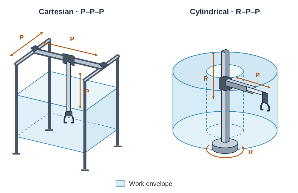
The arrangement of a robot's first three major joints determines the geometry of its work envelope—the total three-dimensional volume of space its end effector can physically access.
| Robot Configuration | Main Joint Layout | Work Envelope Shape | Typical Applications |
|---|---|---|---|
| Cartesian (Gantry) | Three prismatic () | Rectangular box (cuboid) | Pick-and-place packaging, 3D printing, CNC overhead gantries |
| Cylindrical | One rotary, two prismatic () | Cylinder or hollow drum | Machine tending, loading rotary index tables |
| Spherical (Polar) | Two rotary, one prismatic () | Swept spherical shell | Foundry handling, die casting, older spot-welding rigs |
| SCARA | Two rotary (horizontal), one prismatic (vertical) | Cylindrical slice with flat top and bottom | High-speed printed circuit board assembly, insertion tasks |
| Articulated (Revolute) | All rotary (waist, shoulder, elbow: ) | Complex irregular sphere | Automotive body welding, spray painting, multi-axis routing |
SCARA stands for Selective Compliance Assembly Robot Arm. A SCARA arm can flex a little sideways but is stiff up and down. That means a pin can find its way into a hole without jamming, while the arm is still rigid enough to press the pin home. Articulated arms mimic the human arm; with a two- or three-axis wrist added at the end, they achieve six degrees of freedom to access awkward spaces like car interiors.
To position an end effector, the controller references a coordinate frame. In a Cartesian frame (), coordinates are measured along three perpendicular axes from an origin . For example, if a gantry robot's gripper moves from to , the travel required is , , and . The and axes drive while the axis remains stationary. On a cylindrical robot, the same position is given by a base rotation angle , a radial reach , and a vertical elevation .
Industrial Robotics: Applications, Cell Safeguarding, and Statics
Industry deploys robots because they deliver consistent quality, repeat cycles without fatigue, handle high-throughput manufacturing, and take over tasks that are dangerous, dirty, hot, or toxic (such as welding fumes, paint spray, and hot metal casting). However, robots carry high capital installation costs, require skilled technicians to program and maintain, cannot easily exercise human judgement on irregular components, and cause workplace job displacement.
Cell Safeguarding and Safety Practices
Industrial robots move with immense speed and force without sensing human presence unless explicitly safeguarded. Safe cell design requires:
- Fixed perimeter fencing surrounding the entire work envelope.
- Interlocked access gates fitted with safety switches that cut power to the drive motors immediately if opened.
- Optical light curtains or pressure mats at loading points that halt the arm if an operator breaches the light beam.
- Readily accessible emergency stop buttons on the cell perimeter and on the teach pendant.
- Physical hard stops and software limit envelopes to keep the manipulator inside its safe working zone.
Programming Methods
- Lead-through (walk-through): the operator physically guides the robot arm through the desired path while the controller logs the coordinates; typical for smooth spray painting paths.
- Teach pendant: the programmer jogs the arm to key waypoints using a hand-held terminal and saves each position; standard for spot welding and pick-and-place.
- Offline programming: the tool path is simulated and compiled in CAD/CAM software and downloaded directly to the robot cell, avoiding costly production downtime.
In CAD/CAM and CNC integration, CAD (computer-aided design) creates the 3D model, CAM (computer-aided manufacture) converts toolpaths into G-codes (geometric motion instructions) and M-codes (machine functions such as spindle on, coolant on), and CNC (computer numerical control) executes the machining. A CNC machine with rotary encoders tracking table positions is a closed-loop system.
Statics: Forces, Moments, and End Effectors
A force () is a push or pull measured in newtons (). For a supported mass, gravitational force (weight) is calculated using where .
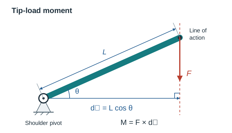
A moment of force () is the turning effect produced about a pivot. It equals the force multiplied by the perpendicular distance from the pivot to the line of action:
If an arm link of length is inclined at an angle above the horizontal, the horizontal perpendicular distance is . This turning effect strains the joint bearings and motors. Because distance multiplies force directly, extending an arm to twice its reach doubles the turning moment at the shoulder. This is why a robot's rated payload is lower when the arm is fully stretched out than when the load is held in close.
The tool mounted to the robot wrist is the end effector:
- Mechanical gripper: motor- or pneumatic-driven fingers or jaws that close to grip rigid solids.
- Vacuum (suction) gripper: a soft elastomeric cup pressed onto a smooth, non-porous workpiece while air is evacuated by a Venturi ejector, allowing atmospheric pressure to secure the part. It spreads the lifting force over a broad surface area, handling delicate sheets of glass or confectionery without crushing them.
- Process tools: specialised tooling heads such as MIG welding guns, spray nozzles, or router spindles.
Accuracy is how closely the end effector reaches a target point in space, while repeatability is how consistently it returns to the same taught point across thousands of cycles (typically within ). Industrial arms are far more repeatable than accurate, which is why positions are taught using physical targets.
Control Theory: Open and Closed Loops, and Gain Calculations
Control systems govern actuators based on input commands. The fundamental distinction between systems is the presence or absence of feedback.
Open Loop Control
An open loop system issues drive signals according to a preset timer or programmed sequence without monitoring whether the commanded action took place. There is no feedback sensor.
Input Demand ──> [ Controller ] ──> [ Driver / Amp ] ──> [ Actuator ] ──> OutputExample: A conveyor motor activated for a timed 5-second pulse. If a box jams the belt or the motor slips, the controller has no way of detecting the failure and assumes the movement occurred.
Closed Loop Control
A closed loop system continuously samples its output using a sensor, feeds this value back, and subtracts it from the set point demand at a comparator to generate an error signal:
The controller processes the error and adjusts motor power to drive the error to zero.
Set Point ──> (+) ──[ Error e ]──> [ Controller ] ──> [ Driver ] ──> [ Motor ] ──+──> Output
               ^ (-)                                                              │
               └─────────────────── [ Sensor / Encoder ] <────────────────────────┘
Gain Calculations
The gain () of a system block is the ratio of its output change to its input change ().
- Blocks in series multiply: for a controller block with gain wired into a motor driver of gain , total forward gain is:
- Closed-loop system gain with negative feedback sensor gain is calculated as:
Negative feedback stabilises systems against load fluctuations, component ageing, and temperature drift.
Actuators: D.C., Stepper, and Servo Motor Selection
Actuators convert electrical signals into mechanical motion. Selecting the right motor requires matching torque, holding power, speed, and positioning requirements.
| Feature | Plain D.C. Motor | Stepper Motor | D.C. Servo Motor |
|---|---|---|---|
| Control signal | Continuous D.C. voltage or PWM duty cycle | Discrete digital step pulses to phase coils | Timed PWM pulses (1.0 ms to 2.0 ms sets angle) |
| Positioning | None without adding an external encoder | Precise open loop by counting pulses | Precise closed loop via internal potentiometer |
| Holding torque at rest | Nil (free wheels when power cut) | High holding torque while coils energised | Holds commanded angle against external force |
| Common failure mode | Overheating under stall | Loses position if overloaded (missed steps) | Internal gear train stripping under shock load |
| Best application | Wheels, fans, continuous conveyors | Gantry lead screws, 3D printer axes, indexers | Robot joints, steering linkages, gripper jaws |
For a school project artefact (such as the 2027 Leaving Certificate Higher Level brief requiring an electro-mechanical solution for an ageing society), small geared D.C. motors or hobby servos connected to a PIC microcontroller offer the most practical, reliable actuation.
Stepper Motor Drive Calculations
A stepper motor rotates through a fixed step angle for each electrical pulse received. Because this motion is predictable, the controller counts pulses to set position in open loop:
If mechanical load resistance exceeds the motor's holding torque, the rotor slips and suffers missed steps, introducing positional error that the open-loop controller cannot detect.
Signal Interfacing: Sensors, ADCs, and DACs
The physical world is analogue: temperature, sound, and pressure vary smoothly over continuous ranges. Digital microcontrollers, however, operate strictly on binary numbers (s and s). Converting between these domains requires specialised hardware interfaces.
Industrial and Robotic Sensors
| Sensor | Operating Principle | Signal Output | Typical Application |
|---|---|---|---|
| Limit switch (microswitch) | Mechanical lever physically deflects to close electrical contacts | Digital | Senses end of travel on a sliding carriage |
| Magnetic reed switch | Internal ferromagnetic contacts snap closed in proximity to a magnetic field | Digital | Senses pneumatic cylinder piston position non-invasively |
| Inductive proximity sensor | Senses high-frequency eddy current damping caused by nearby metal | Digital | Counts steel gear teeth or cans on a conveyor in oily/dusty cells |
| Capacitive proximity sensor | Detects changes in electrostatic capacitance caused by any nearby target | Digital | Detects non-metallic parts like plastic containers or liquid levels |
| Optical / photoelectric beam | Infared light beam is interrupted or reflected back by a component | Digital | Safety cell perimeter guarding; parts counting |
| Ultrasonic sensor | Emits high-frequency sound burst and times the reflected echo pulse | Analogue / Digital | Distance measurement and obstacle detection |
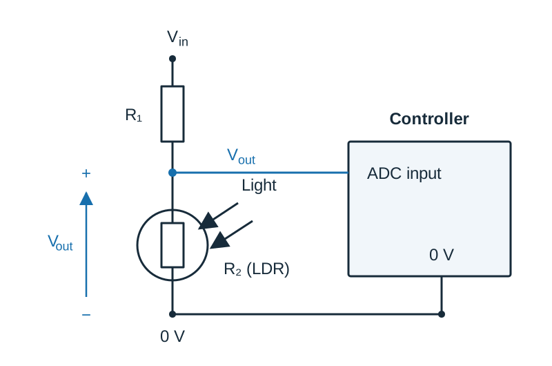
| LDR (light-dependent resistor) | Cadmium sulfide resistance decreases as illumination increases | Analogue | Ambient daylight sensing and optical sorting |
| Thermistor (NTC) | Semiconductor resistance drops as temperature rises | Analogue | Motor thermal protection; environmental monitoring |
| Potentiometer | Wiper moves across resistive track to divide supply voltage | Analogue | Joint angle position sensing in analogue servos |
| Optical rotary encoder | Slotted disc interrupts optical beam to generate high-speed pulse trains | Digital pulses | Closed-loop velocity and position feedback on motor shafts |
Digital sensors wire directly to controller input pins. Analogue sensors must be arranged in a potential divider () and fed into an A/D converter (ADC).
Analogue-to-Digital Conversion (ADC)
An ADC samples an analogue voltage and quantises it into a discrete digital binary integer. An -bit ADC divides its reference voltage () into distinct quantisation intervals. The step size is its resolution:
The converted digital integer code is the whole number of steps that fit into the measured input voltage (). For a 10-bit ADC ( levels, codes 0 to 1023) operating with , the resolution is .
Digital-to-Analogue Conversion (DAC)
A D/A converter (DAC) performs the reverse operation, converting digital words from a processor into a stepped analogue voltage to drive proportional valves or speed controls:
Programmable Devices, Logic Types, and Component Sizing
Automated control relies on programmable controllers rather than hardwired logic:
- PIC (Peripheral Interface Controller): a single-chip microcontroller containing processor, RAM, flash memory, and I/O pins. It is inexpensive, compact, and ideal for embedded devices and school project artefacts.
- PLC (Programmable Logic Controller): a ruggedised industrial computer built to endure factory electrical noise, dust, vibration, and moisture. Its inputs are optically isolated to shield the CPU, and its outputs drive high-power contactors and solenoids directly.
Combinational and Sequential Logic
- Combinational logic: outputs depend exclusively on the current combination of inputs at that exact instant. There is no memory.
Example: A two-hand safety press requiring Left Button (), Right Button (), and Guard Closed () simultaneously before the press ram activates: .
| 0 | 1 | 1 | 0 |
| 1 | 0 | 1 | 0 |
| 1 | 1 | 0 | 0 |
| 1 | 1 | 1 | 1 |
Releasing either button causes the ram to stop immediately.
- Sequential logic: outputs depend on the current inputs as well as the history of previous operations. The system relies on internal memory (latches or flip-flops).
Example: A conveyor motor started by a momentary pushbutton must remain running after the button is released, until a separate STOP button is pressed. In microcontroller code, an internal memory bit (RUN) is latched:
if START = 1 then RUN = 1
if STOP = 1 then RUN = 0
MOTOR = RUN
In industrial ladder logic, this is achieved with a seal-in latch circuit where an auxiliary contact of the motor output is wired in parallel with the START button.
Seven-Segment Displays
A seven-segment display consists of seven individual LEDs arranged as a figure-8, designated segments through (clockwise from top, with in the centre), plus a decimal point (). They are produced in two wiring configurations:
- Common cathode: all LED cathodes are joined to . An individual segment illuminates when its corresponding input pin is driven HIGH ().
- Common anode: all LED anodes are joined to . A segment illuminates when its pin is driven LOW ().
Every segment must have its own current-limiting resistor to maintain uniform brightness regardless of how many segments are active. Sizing uses Ohm's law:
For a supply, LED forward drop , and forward current :
Displays are driven directly from seven output pins or via a BCD-to-seven-segment decoder driver IC, which translates a 4-bit binary input into the correct segment combination, saving controller pins.
Transistor Driver Sizing and Inductive Clamping
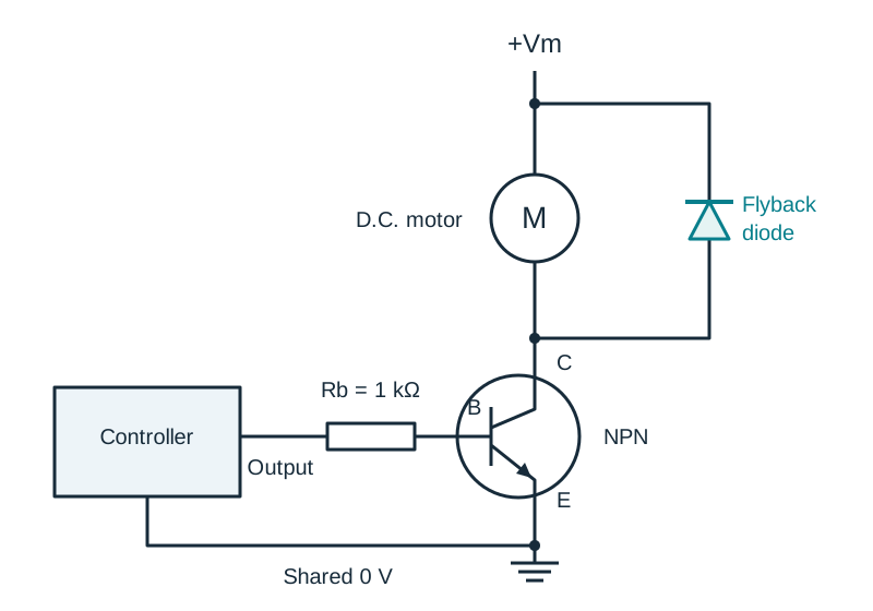
A microcontroller pin cannot source more than . To switch higher-current actuators like D.C. motors or solenoid valves, an NPN bipolar transistor or N-channel MOSFET is used as a digital switch.
If a D.C. motor draws collector current , the transistor has current gain , and base-emitter drop :
Because is not a standard value, choose the next standard value below it—. A slightly lower resistance supplies slightly more base current than the bare minimum, ensuring the transistor saturates fully into conduction and runs cool. Always connect a reverse-biased flyback diode in parallel across any inductive coil (motor or solenoid). When the transistor turns off, the collapsing magnetic field induces a high-voltage back-EMF spike; the diode safely circulates this transient current, protecting the transistor from breakdown.
Control Strategies, Pneumatics, and Force Calculations
When automating machinery, engineers choose between three control strategies:
- Totally pneumatic: cylinders are piloted by air-operated mechanical valves (roller trip valves and pushbuttons). Best for explosive atmospheres, paint spray booths, and flour mills where electrical sparks present an explosion hazard, or in wet washdown environments. However, circuits become bulky and difficult to modify for complex sequences.
- Electro-pneumatic: pneumatic cylinders provide mechanical power while solenoid directional valves are orchestrated by a PLC or PIC. This combines the high force, rapid motion, and clean action of compressed air with the programmable flexibility, counters, and timers of digital software. It is the dominant industrial choice.
- Totally electronic: electric linear actuators, stepper motors, and servomotors handle both control and actuation. Best for clean, compact consumer devices, medical equipment, and precise multi-axis positioning, but high-force electric actuators are heavier and more expensive than pneumatic cylinders and can overheat if stalled.
Standard Pneumatic Hardware
- Single-acting cylinder (SAC): compressed air pushes the piston along its outstroke; an internal mechanical spring returns it on the instroke. It requires one working air port and is controlled by a 3/2 valve.
- Double-acting cylinder (DAC): powered by air on both the outstroke and the instroke via two separate working ports. Controlled by a 5/2 valve.
- 3/2 Directional control valve: three ports (1: Supply, 2: Working line, 3: Exhaust) and two switching positions.
- 5/2 Directional control valve: five ports (1: Supply, 2: Working line to instroke port, 4: Working line to outstroke port, 3 and 5: Exhausts) and two positions.
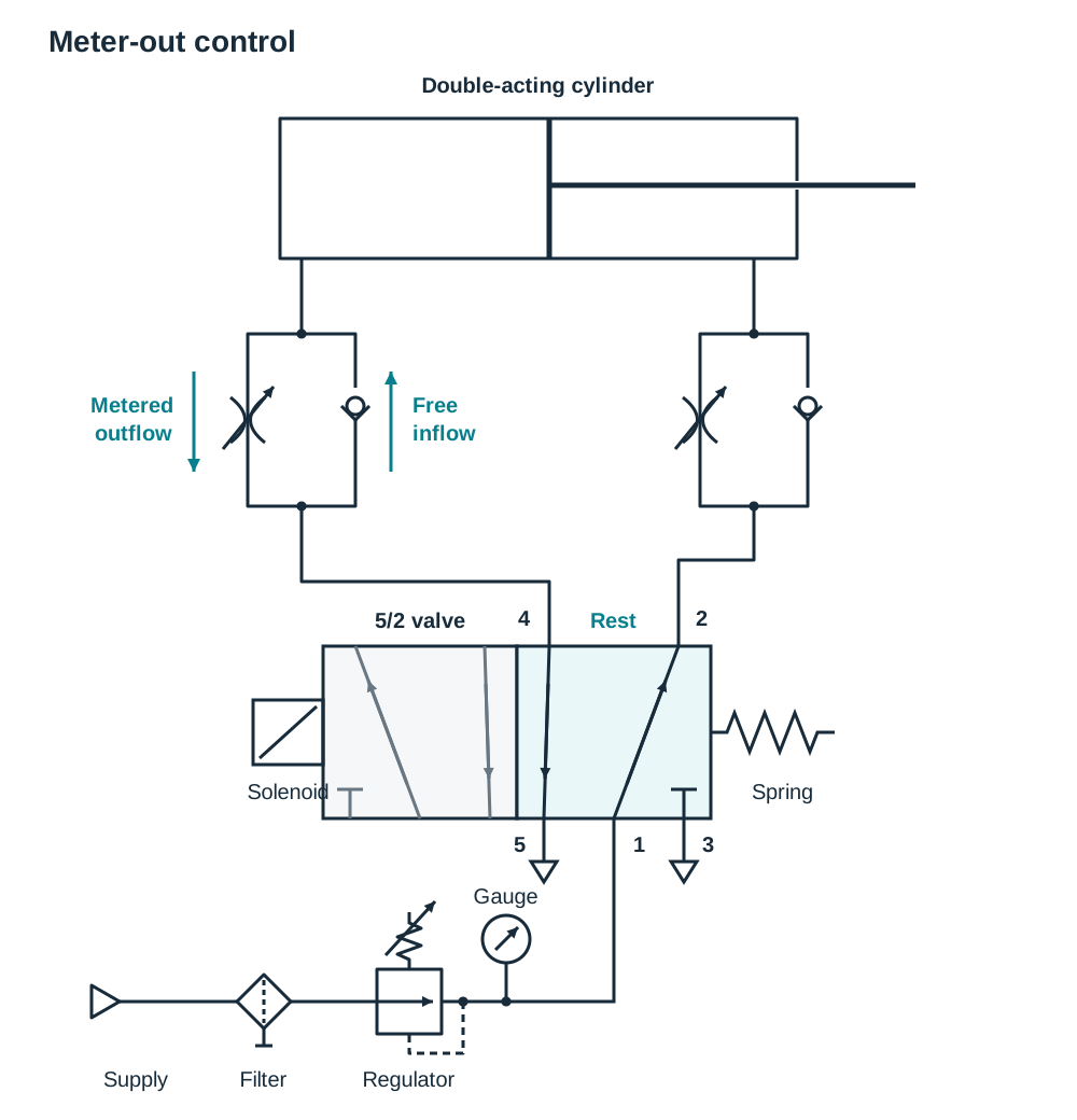
- One-way flow control valve: contains a restrictor in parallel with a non-return check valve. In cylinder speed control, it is plumbed for meter-out control—air freely enters the driven chamber while air escaping through the exhaust side is throttled. This prevents jerky stick-slip motion and gives smooth stroke speeds.
In standard shorthand sequencing, denotes cylinder extending, denotes cylinder retracting, denotes the retracted limit sensor, and denotes the extended limit sensor.
Pneumatic Cylinder Force Calculation
The theoretical force exerted by a pneumatic cylinder depends on supply pressure and effective piston area:
Where is force in newtons (), is gauge pressure in pascals (), and is the effective surface area in square metres (). Note the pressure conversion: .
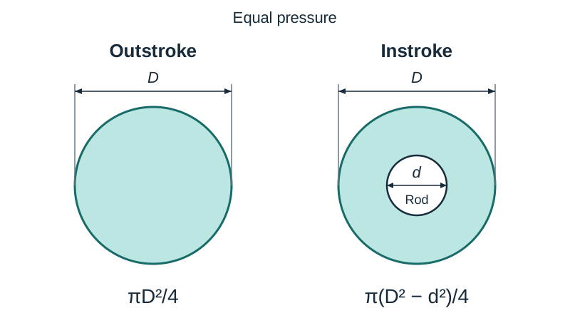
On the outstroke, air acts against the full circular bore diameter (). On the instroke, the piston rod of diameter () obstructs a portion of the surface area, reducing the working area: . Consequently, a double-acting cylinder always pulls with less force than it pushes.
Bill of Materials and Circuit Costing
The syllabus requires you to design, cost and build circuits, so you may be asked to price a design you have drawn. Set it out as a bill of materials listing every part — including tubing and fittings — with quantity, unit cost and line total, and give the overall total in euro:
| Item | Description | Quantity | Unit Cost (€) | Total Cost (€) |
|---|---|---|---|---|
| 1 | Double-acting cylinder ( bore, stroke) | 1 | 28.00 | 28.00 |
| 2 | 5/2 Single solenoid, spring-return directional control valve | 1 | 34.00 | 34.00 |
| 3 | One-way flow control restrictor valves | 2 | 7.50 | 15.00 |
| 4 | Filter, pressure regulator, and gauge assembly | 1 | 32.00 | 32.00 |
| 5 | Magnetic reed position limit switches | 2 | 11.00 | 22.00 |
| 6 | Polyurethane pneumatic tubing and push-fit connectors | 1 set | 14.00 | 14.00 |
| 7 | Electronic solenoid driver interface module | 1 | 10.00 | 10.00 |
| Total | €155.00 |
Process Drawing: Flowcharts, Grafcet, and Circuit Diagrams
Leaving Certificate examination questions consistently reward mastery of three graphical engineering representations: flowcharts, Grafcet charts, and pneumatic circuit schematics.
1. Flowchart Construction Rules
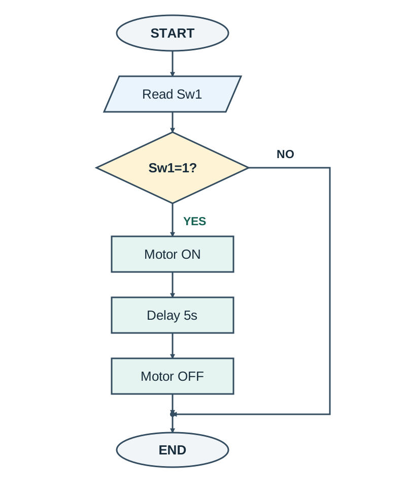
- Oval / Capsule: START or END terminators.
- Parallelogram: Input/Output operations (reading a sensor, displaying a message).
- Rectangle: Process tasks (energising a motor, advancing a counter, setting a timer).
- Diamond: Decision checks. Must have exactly two exit paths, each clearly labelled YES or NO.
2. Grafcet (Sequential Function Charts)
Grafcet represents automated sequences without the clutter of loops:
- Steps: drawn as numbered squares representing stable phases. The initial active step is drawn with a double border.
- Actions: drawn in rectangular boxes linked to the right of their corresponding step.
- Transitions: horizontal bars crossing the vertical link between steps. Each transition has a logical condition (receptivity) written alongside it.
Firing Rule: A transition fires only when the step immediately above it is active AND its transition condition is TRUE. Firing deactivates the prior step and activates the next step in a single instant. Steps and transitions must alternate strictly.
3. Step-by-Step Layout of an Electro-Pneumatic Circuit
When asked to draw a circuit for a double-acting cylinder controlled by a solenoid valve with speed control, draw components in this sequence:
- At the bottom, draw the air supply symbol (a circle with an outward-pointing solid equilateral triangle) followed by the filter, regulator, and gauge (FRL) conditioning unit.
- Above it, draw the 5/2 valve as two adjacent squares. In the unactuated (spring-return) position square, draw airflow arrows connecting supply port 1 to working port 2, and working port 4 venting to exhaust port 5. Number all ports: 1 = mains air supply; 2 and 4 = working lines; 3 and 5 = exhausts.
- Draw the actuators on the valve ends: a solenoid symbol (rectangle with a diagonal line) on the left actuation end, and a mechanical spring symbol (zig-zag) on the right return end.
- At the top of the diagram, draw the double-acting cylinder: cylindrical barrel, piston, and protruding rod, with working ports at the rear and front ends.
- In the lines connecting valve ports 2 and 4 to the cylinder, insert one-way flow control valves. Orient the non-return check valves so air flows freely into the cylinder while escaping exhaust air is forced through the adjustable restrictor (meter-out speed control).
- Connect port 4 to the cylinder's rear port (outstroke) and port 2 to the front port (instroke) with straight, unbroken lines.
Key terms
- Degree of Freedom
- An independent coordinate or axis of motion (linear or rotary) along which a robotic joint or manipulator can move.
- Revolute Joint
- A mechanical joint that produces angular, turning motion about a fixed pivot axis, operating like a hinge.
- Prismatic Joint
- A mechanical joint that produces straight-line, sliding linear movement along a single axis.
- Work Envelope
- The total three-dimensional volume of space that a robot end effector can physically access.
- End Effector
- The specialised hand, gripper, or processing tool attached to the wrist of a robot arm to carry out work.
- Moment of Force
- The turning effect of a force about a pivot, equal to the force multiplied by the perpendicular distance from the pivot to the line of action (Nm).
- Open Loop
- A control strategy that sends operational commands according to a preset program or timer without sensing or verifying the actual physical output.
- Closed Loop
- A control strategy that continuously measures actual output using a sensor, feeding the signal back to compare with the set point and correct errors.
- Feedback
- The transmission of real-time output measurements back to a system comparator to allow automatic error correction.
- Error Signal
- The mathematical difference between the desired set-point demand and the measured output feedback signal (Error = Demand - Output).
- Gain
- The ratio of the output signal change to the input signal change across an electronic amplifier or control block.
- Stepper Motor
- An electric actuator that rotates in discrete, fixed angular increments per electrical pulse, offering precise open-loop positioning.
- D.C. Servo Motor
- An integrated actuator assembly comprising a D.C. motor, gear reduction train, position feedback sensor, and error amplifier that holds a commanded angle.
- A/D Converter
- An analogue-to-digital electronic converter that samples continuous analogue voltages and quantises them into binary integer codes.
- D/A Converter
- A digital-to-analogue converter that translates binary data words from a processor into a continuous proportional voltage or current.
- Combinational Logic
- A digital switching system whose output state is determined strictly by the present state of its inputs, having zero memory of past events.
- Sequential Logic
- A digital control system whose outputs depend on both current inputs and the sequence of prior events, relying on internal memory latches.
- Grafcet
- A sequential function chart standard that models industrial control sequences using alternating steps, transitions, and actions.
- Double-Acting Cylinder
- A pneumatic actuator that uses compressed air applied to separate ports to power both the outstroke and instroke movements.
- 5/2 Valve
- A directional control valve having five ports and two switching states, used as the standard control element for double-acting cylinders.
- Flyback Diode
- A reverse-biased diode placed in parallel across an inductive coil (motor or solenoid) to suppress damaging high-voltage back-EMF spikes during switch-off.
Check yourself
What is the mechanical difference between a revolute joint and a prismatic joint?
A revolute joint produces angular or turning motion about a fixed pivot axis, whereas a prismatic joint produces straight-line sliding linear translation.
Why is a SCARA robot arm specially suited for electronics assembly?
Its arm is flexible horizontally (compliance) so pins locate into holes without jamming, but stays completely rigid vertically to press components home.
How is the error signal calculated in a closed loop control system?
The error signal is the set-point demand minus the measured output feedback signal (Error = Demand - Output).
How many pulses are needed to turn a 1.8° stepper motor through 270°?
Pulses = Target Angle / Step Angle = 270° / 1.8° = 150 pulses.
A 32 mm bore pneumatic cylinder operates at 5 bar. Calculate the outstroke force.
Area = π(0.032)² / 4 = 8.04 × 10⁻⁴ m²; Pressure = 500 000 N/m²; Force = 500 000 × 8.04 × 10⁻⁴ = 402 N.
Name a non-contact sensor used to detect when a pneumatic cylinder has reached its stroke end, and explain how it operates.
A magnetic reed switch: a permanent magnet fitted to the moving piston closes two flexible metal contacts through the cylinder barrel wall, generating a digital ON signal.
In a Grafcet sequential function chart, how is the initial step represented, and under what conditions does a transition fire?
The initial step is drawn with a double border; a transition fires only when its immediately preceding step is active and its transition condition evaluates to true.
Why must every segment in a seven-segment display have its own current-limiting resistor?
A shared resistor would cause the voltage drop and segment brightness to change depending on how many segments are illuminated simultaneously.