

This note covers the main metal content you need for Leaving Certificate Technology: classification, properties and testing, structure and defects, workshop processing, heat treatment, joining, surface finishing, and the production and sustainability issues that follow from them. It balances core workshop knowledge with the higher analytical depth required for Section C Materials Technology and demonstrates how to apply metal engineering in the 2027 coursework project.
1. Classification and Atomic Structure: Ferrous, Non-Ferrous, and Alloys
Metals are grouped into three primary categories based on composition and the presence of iron:
Ferrous Metals
Ferrous metals contain iron () as their main constituent. Most are magnetic and will corrode into rust when exposed to moisture and oxygen. The amount of carbon dissolved in the iron determines their mechanical properties:
- Mild steel (approx. 0.15% to 0.3% carbon): ductile, malleable, easily welded and machined. Used for general fabrication, structural angle and box section, and the frames and chassis of school projects.
- Medium-carbon steel (approx. 0.3% to 0.7% carbon): stronger and tougher than mild steel and can be hardened and tempered. Used for shafts, axles, gears, and garden tools.
- High-carbon steel (approx. 0.7% to 1.4% carbon): hard and wear-resistant, but brittle if not tempered. Used for cutting tools, drill bits, taps, dies, and cold chisels.
- Cast iron (2% to 4% carbon): hard with exceptional compressive strength, but brittle in tension. It absorbs vibration effectively, making it the standard choice for machine beds and vice bodies.
- High-speed steel (HSS): an alloy steel containing tungsten, chromium, and vanadium. It retains its cutting hardness even at dull red heat, making it the standard material for twist drill bits and lathe tool bits.
Non-Ferrous Metals
Non-ferrous metals contain no iron. They cannot rust, and most (though not all — nickel is a magnetic exception) are non-magnetic. Many form a thin, protective surface oxide film that prevents deeper chemical attack:
- Aluminium: low density (approx. ), high strength-to-weight ratio, and easily formed. Its immediate surface oxide prevents deep corrosion.
- Copper: exceptionally ductile, malleable, and an outstanding electrical and thermal conductor. Used for wiring, central heating pipework, and printed circuit tracks.
- Zinc: low melting point with good corrosion resistance. Predominantly used as a protective sacrificial coating (galvanising) on steel.
Alloys and Lattice Structure
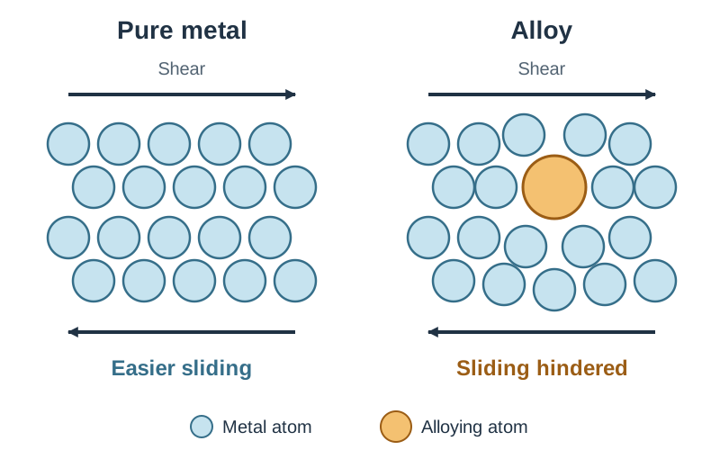
Pure metals consist of orderly crystal layers of identical atoms that slide over each other under load. An alloy is a mixture of two or more elements, at least one being a metal. Introducing atoms of a different size distorts the regular crystalline lattice. This distortion prevents the atom layers from sliding easily past one another, significantly increasing hardness and tensile strength.
- Brass (): harder than pure copper, easily machined, resists corrosion, and produces low friction in moving components.
- Bronze (): tough, wear-resistant, and highly resistant to salt-water corrosion; used for marine hardware and sleeve bearings.
- Duralumin (): combines the low density of aluminium with significantly greater tensile strength; widely used in aircraft structures and lightweight frames.
- Stainless steel (ferrous alloy of iron, carbon, and at least chromium): chromium forms an invisible, self-repairing surface barrier of chromium oxide that stops rusting, making it ideal for medical instruments and food processing equipment.
2. Mechanical Properties, Load Types, and Workshop Testing
Selecting an engineering metal requires balancing mechanical properties against the forces the part must endure in service.
The Five Ways a Part Can Be Loaded
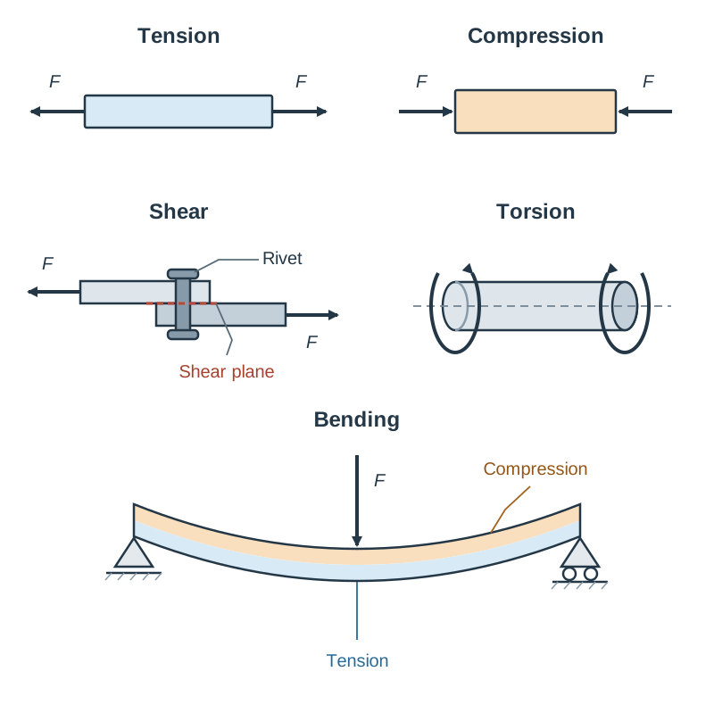
- Tension: a pulling or stretching force acting along the length of a part (e.g. the cable of a patient hoist).
- Compression: a pushing or squashing force that tries to crush or shorten a part (e.g. the support legs of a hospital bed).
- Shear: two opposing parallel forces acting across a part, trying to slice it (e.g. the rivet in a lap joint or sheet metal cut by tin snips).
- Torsion: a twisting force about the long axis of a part (e.g. a motor drive shaft or screwdriver blade).
- Bending: a transverse load that puts the convex face into tension and the opposite concave face into compression (e.g. an assistive grab rail loaded downwards).
Core Property Definitions
- Hardness: the resistance of a surface to scratching, wear, cutting, and indentation.
- Toughness: the ability to absorb sudden impact energy without fracturing. Toughness is the opposite of brittleness.
- Elasticity: the ability to deform under load and return completely to original dimensions once the load is released.
- Plasticity: the ability to undergo permanent deformation beyond the yield point without breaking.
- Malleability: the capacity to be hammered, rolled, or stamped into thin sheets without cracking.
- Ductility: the capacity to be drawn out into long, thin wires under tensile load.
Simple Workshop Comparison Tests
In every comparison test, the specimens must have identical dimensions and cross-sections, and the load, drop height, or number of blows must remain constant — otherwise you are testing the specimen dimensions rather than the metal itself.
- Hardness (File Scratch Test): Draw a standard engineer's file across different metal samples using equal hand pressure. The metal with the shallowest scratch is the hardest.
- Hardness (Indentation Test): Rest a centre punch on the metal and drop a fixed mass from a set height down a guide tube. Measure the diameter or depth of the resulting dimple; smaller dimples indicate higher hardness.
- Toughness (Vice Impact Test): Clamp identical test strips in a bench vice with equal protruding length. Strike each specimen with a consistent blow using a ball pein hammer. Tough metals (such as mild steel) bend plastically, whereas brittle metals (such as cast iron) snap.
- Ductility (Repeated Bend Test): Clamp strips in a vice and bend them back and forth through until fracture occurs. The metal withstanding the greatest number of cycles has the highest ductility.
3. Structural Defects, Tensile Testing, and Stress Calculations
Solid metals consist of microscopic crystalline grains. How these grains form and interact dictates macroscopic performance.
Work Hardening and Structural Defects
- Work Hardening: Plastically deforming a metal at room temperature (by rolling, hammering, or bending) distorts the crystal lattice and creates internal dislocations. This makes the metal harder and stiffer, but noticeably less ductile. Continued bending without annealing causes micro-cracking and eventual fatigue failure.
- Internal Defects: Inconsistencies severely impair structural strength:
- Porosity: gas bubbles trapped during casting create internal voids, reducing the effective load-bearing area.
- Slag Inclusions: non-metallic impurities trapped in weld beads create internal fracture planes.
- Micro-cracks and Sharp Corners: notches act as stress concentrators. Under repeated cyclic loading, stress concentrates at the notch root, initiating catastrophic mechanical fatigue.
Reading the Tensile Test Graph
When a metal specimen is subjected to a tensile test, stress is plotted against strain:
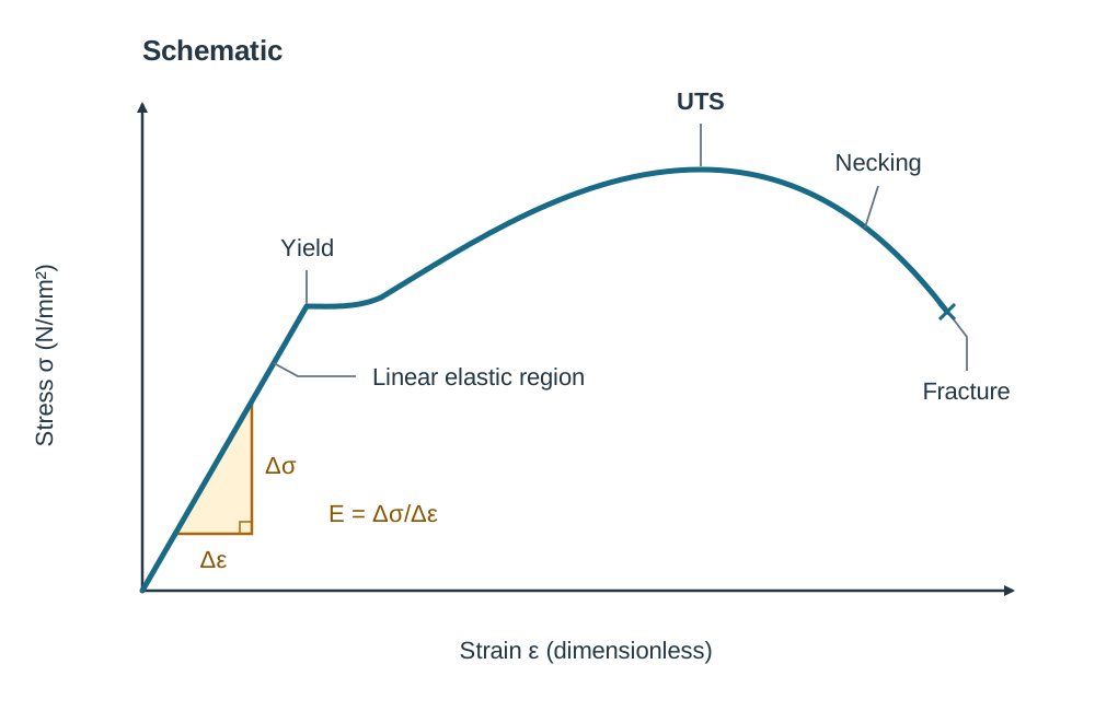
- Linear (Elastic) Region: stress is directly proportional to strain. When load is released, the specimen springs back to its original length. The slope of this line equals Young's modulus ().
- Yield Point: the stress level at which the metal begins to deform permanently (plastically). Designers ensure working stresses remain comfortably below this point.
- Ultimate Tensile Strength (UTS): the maximum nominal stress the material can support.
- Necking and Fracture: ductile metals thin locally (necking) before pulling apart; brittle metals break abruptly with minimal plastic extension.
Stress and Factor of Safety Calculations
Units reminder: . Dividing force in by area in yields stress in ().
A factor of safety accounts for unexpected overloads, dynamic shocks, material defects, and gradual wear.
4. Workshop Processing: Marking Out, Thread Cutting, Wasting, and Shaping
Manufacturing accurate components requires methodical layout, safe machining, and correct tool selection.
Marking-Out Equipment and the Datum Principle
All measurements must reference a single, prepared datum edge or face. Measuring sequentially from hole to hole causes individual marking errors to accumulate; measuring from a single datum edge isolates each measurement.
- Steel rule: reads lengths directly; view with your eye directly over the graduation line to prevent parallax error.
- Engineer's blue (marking-out fluid): a thin blue dye brushed onto the metal before scribing. Scribed lines show up brightly against the dark surface, making them easy to follow.
- Engineer's try square: checks and scribes layout lines at to the prepared datum edge.
- Scriber: a hardened steel needle that scratches fine, permanent guide lines onto metal surfaces.
- Centre punch: creates a conical dimple at intersecting lines to locate twist drill tips and stop the bit from wandering.
- Odd-leg (jenny) callipers: feature one bent leg that hooks against a datum edge to scribe parallel lines, or to locate the centre of round bar.
- Dividers: scribe circles, arcs, and step off equal pitch spacings from a centre-punch mark.
- Templates: when producing multiple identical parts, scribing around one accurate template guarantees consistency and avoids repeating measuring errors.
Cutting Screw Threads by Hand
- Internal Threads (Tapping):
- Drill the correct tapping size hole (e.g. a drill for an M6 thread) so enough metal remains for the tap to cut the thread teeth.
- Lightly countersink the hole entrance so the tap starts easily.
- Fit the taper tap into a tap wrench and align it square to the face using a try square. If started crooked, the tap will bind and snap.
- Apply cutting fluid, rotate one full turn clockwise, then back off a quarter turn. This reverse turn shears off metal chips (swarf) so they do not jam the flutes.
- Follow with the second tap, and complete blind holes with the plug (bottoming) tap to cut full thread depth to the bottom.
- External Threads (Die Cutting):
Chamfer the end of the round bar, fit the split die into a die stock with the lead-in face forward, hold square, lubricate, and use the same one-turn-forward, quarter-turn-back motion.
Wasting: Cutting, Filing, and Safe Drilling
- Wasting (cutting away metal): A hacksaw removes bulk material to rough length. Cross-filing removes material quickly across the work, whereas draw-filing along the edge produces a smooth, straight, square finish.
- Safe Drilling Procedures:
- Always clamp work firmly in a drill vice; never hold sheet metal by hand.
- Secure the vice to the pillar drill table.
- Adjust pulley belts for the correct spindle speed: high RPM for small drills in soft aluminium; low RPM for large drills in mild steel.
- Remove the chuck key before switching on power.
- Clear swarf with a hand brush once the spindle stops — never use bare hands.
Deforming, Casting, and Chemical Processing
- Deforming (reshaping without removing metal): Bar and sheet are bent cold over a former or in folding bars, or heated to bright red first if the section is heavy, because heat makes the metal more malleable and reduces cracking from work hardening.
- Casting: Molten metal fills a mould cavity. In sand casting, molten aluminium or iron is poured into a sand mould formed by a pattern, split into a cope (top box) and drag (bottom box), with a runner to introduce metal and a riser to vent air. In die casting, molten non-ferrous alloys are injected under high pressure into reusable steel dies for high-volume batch runs.
- Chemical Processing: Material removal using chemical reactions. In school workshops, printed circuit boards (PCBs) are produced by dissolving unprotected copper in heated ferric chloride solution. Always wear eye protection and chemical gloves, and neutralise spent chemical waste before disposal.
5. Thermal Processing and Heat Treatment of Steels
Heat treatment alters the crystalline structure and mechanical properties of carbon steels through controlled thermal cycles without changing the shape of the component:
Heat-Treatment Summary
| Process | Purpose | Cooling Method |
|---|---|---|
| Hardening | Maximises hardness and wear resistance; makes steel brittle | Rapid quench in cold water, brine, or oil |
| Tempering | Relieves internal stresses; restores toughness at small hardness cost | Reheat to specific oxide colour, then quench |
| Annealing | Softens work-hardened metal; restores maximum ductility | Cool as slowly as possible (in furnace or hot ash) |
| Normalising | Refines coarse grains from forging; produces uniform strength | Cool naturally in still air |
| Case Hardening | Produces hard wear-resistant skin on low-carbon steel | Carburise at , then quench in water |
Hardening and Tempering High-Carbon Steel
- Hardening: Heat high-carbon steel slowly to cherry red (approx. ), allowing carbon to dissolve into the iron lattice. Quench rapidly in cold water. This traps carbon in a needle-like crystal structure called martensite. The steel becomes exceptionally hard and wear-resistant, but glass-brittle and full of internal stresses.
- Tempering: Follows hardening immediately. Clean the hardened steel with emery cloth to expose bright metal. Heat gently behind the cutting edge. As heat conducts forward, an oxide film forms, displaying characteristic temper colours:
- Pale Straw (): lathe tools, scrapers (maximum hardness retained).
- Medium Brown (): drill bits, taps, dies.
- Brownish-Purple (): cold chisels, punches, shear blades.
- Blue (): springs, screwdrivers (maximum toughness and flexibility).
The instant the required colour reaches the cutting edge, quench fully in water to halt further heating.
Case Hardening (for Mild Steel)
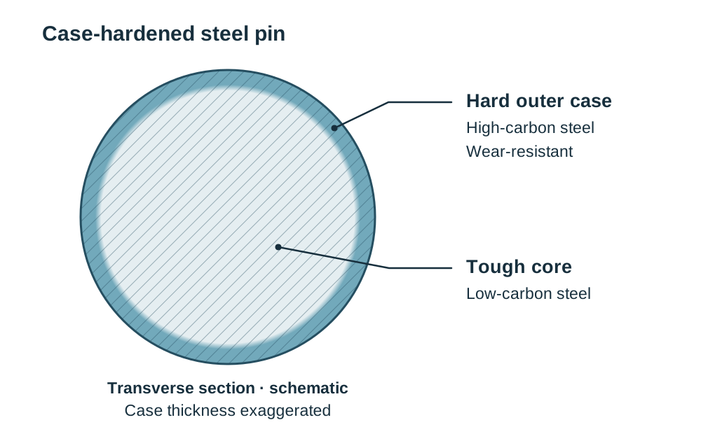
Mild steel contains only 0.15% to 0.3% carbon — too little to harden right through by simple quenching. Case hardening adds carbon to the outer surface only, producing a hard, wear-resistant outer skin (the case) over a tough, shock-absorbing low-carbon core.
- Heat the mild steel part to bright red (approx. ) in a brazing hearth.
- Dip or roll the hot steel in a carbon-rich case-hardening compound so the powder fuses to the surface.
- Return to the hearth and hold at red heat for several minutes. Carbon diffuses into the outer surface layer — a stage called carburising.
- Repeat the dip and reheat cycle to build a deeper carburised skin.
- Finally, reheat to cherry red and quench in cold water. The high-carbon skin transforms into hard martensite, while the low-carbon core remains ductile and tough. Ideal for gear teeth, hinge pins, and spanner jaws.
6. Joining Metals: Metallurgical, Mechanical, and Chemical Methods
Assembling metal parts involves permanent methods (which cannot be dismantled without cutting or damaging the components) or semi-permanent mechanical joints (which allow disassembly for maintenance and recycling):
Metallurgical Joining
- Soft Soldering: Uses a filler alloy (tin/copper or tin/lead) that melts below 450 °C (common electrical solders melt at 180–250 °C). The base metals do not melt. A chemical flux dissolves surface oxides and prevents re-oxidation during heating, allowing the solder to flow into the joint by capillary action.
- Brazing: Joins metals using a brass filler rod that melts above 450 °C but below the melting point of the parts themselves. In school workshops, brass spelter is melted on a brazing hearth at roughly 800–900 °C using brazing flux. The parent metals stay solid. Brazing produces significantly stronger joints than soft solder.
- Welding (MIG, TIG, Arc): The edges of the parent metals are melted directly at temperatures exceeding . The molten pools blend together, usually with a filler rod of matching composition, creating a continuous joint equal in strength to the base metal.
Mechanical Joining
- Threaded Fasteners (Nuts, Bolts, Machine Screws): Semi-permanent fixings passing through clearance holes or engaging tapped internal threads. They allow non-destructive disassembly for inspection, component replacement, and end-of-life material sorting.
- Rivets: Permanent mechanical fasteners. A cylindrical rivet passes through aligned clearance holes, and its protruding shank is deformed using a ball pein hammer and rivet snap, or pulled with a pop-rivet tool (blind riveting). Riveting introduces no heat, preventing thermal distortion in thin aluminium sheet.
Chemical Joining (Adhesives)
- Epoxy Resins: Two-part chemical adhesives consisting of an epoxy resin and a hardener. When mixed in the proportions specified by the manufacturer (often equal parts), they cure via an exothermic thermosetting reaction. They form high-strength, waterproof bonds between dissimilar metals. Surfaces must be thoroughly degreased and abraded to provide mechanical keying.
7. Degradation, Galvanic Corrosion, and Surface Finishes
Corrosion is the electrochemical deterioration of a metal reacting with its environment.
Rusting and Galvanic (Bimetallic) Corrosion
Rusting applies strictly to ferrous metals and requires both moisture and oxygen together:
Because rust is porous and flaky, it spalls off, exposing fresh metal to ongoing attack.
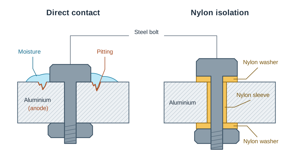
Galvanic corrosion occurs when two electrochemically different metals make electrical contact in the presence of an electrolyte (such as moisture). The more reactive metal becomes an anode and corrodes rapidly, while the less reactive metal is protected. For example, using steel bolts in an aluminium frame causes aggressive pitting in the aluminium around the bolt. Prevention methods:
- Use fasteners of matching metal, or use stainless steel.
- Fit non-conductive nylon washers and sleeves to break electrical contact.
- Coat the joint in paint or sealant to exclude moisture.
- Design rules against corrosion: avoid open channels that trap water, include drain holes in box sections, and radius internal corners so paint does not thin out.
Surface Finishing Techniques
| Finish | Application Procedure | Protection Mechanism | Typical Applications |
|---|---|---|---|
| Paint & Primer | Degrease, abrade, apply anti-corrosive primer (e.g. zinc phosphate), followed by top coats. | Physical barrier stopping moisture and air contact. | Steel gates, machinery frames, vehicle chassis. |
| Plastic Dip Coating | Clean and degrease metal; preheat in oven to ; immerse into fluidised bed of polyethylene powder; post-heat briefly to fuse. | Thick, waterproof, warm-to-touch, electrically insulating plastic skin. | Assistive grab rails, tool handles, wire baskets. |
| Powder Coating | Electrostatically spray dry polymer powder onto earthed metal, then bake in an oven at to cure. | Tough, uniform, scratch-resistant polymer barrier. | Bicycle frames, metal office furniture, appliances. |
| Hot-Dip Galvanising | Clean steel in acid pickle, then immerse in molten zinc at . | Barrier protection plus sacrificial protection: zinc corrodes preferentially even if scratched. | Outdoor lamp posts, motorway barriers, farm gates. |
| Anodising | Clean aluminium acts as anode in an acid bath; an electric current is passed through. | Electrochemically thickens the natural aluminium oxide layer; porous layer absorbs dyes before sealing. | Architectural cladding, smartphone cases, torch bodies. |
| Lacquering | Clean, polish metal bright, and spray with clear cellulose or acrylic lacquer. | Thin transparent barrier stopping atmospheric tarnish while maintaining metallic sheen. | Polished brass instruments, decorative copper ware. |
8. Production Systems, Quality Standards, and 2027 Coursework Integration
Engineering decisions balance mechanical function with manufacturing constraints, formal quality control, and lifecycle sustainability.
Sustainability and the Circular Economy
Metals can be recycled indefinitely without losing mechanical performance:
- Recycling aluminium saves about 95% of the energy needed to extract new metal from bauxite ore using the electrolytic Hall-Héroult process.
- Recycling steel in an electric arc furnace uses roughly 60–70% less energy than making virgin steel from iron ore in a blast furnace.
- Design for Disassembly (DfD): Avoid mixed-material permanent adhesives and permanent welds where different metals meet. Use standard threaded fasteners and label alloys to facilitate end-of-life sorting and recycling.
Production Techniques and Quality Standards
- Once-Off (Craft) Production: Single products manufactured by hand using general workshop tools. Highly flexible with zero dedicated tooling cost, but slow and reliant on individual skill.
- Batch Production: Producing identical batches using dedicated jigs (which guide cutting tools) and fixtures (which locate and hold work securely).
- Tolerance: The permissible variation on a dimension (e.g. ). Dimensions outside tolerance are rejected.
- Go/No-Go Gauge: A double-ended production gauge used to check tolerances quickly without reading a scale. The 'go' end must enter the hole; the 'no-go' end must not.
- Quality Standards: The NSAI (National Standards Authority of Ireland) certifies product standards with the NSAI mark; ISO 9001 audits an organisation's quality management systems; CE marking declares compliance with EU health, safety, and environmental protection directives.
Material Selection Table for Assistive Design
Exam questions routinely require you to name a specific metal, justify its property, and match it to product function. Here is a model response for a folding mobility walker:
| Part | Chosen Material | Working Property | Justification in Function |
|---|---|---|---|
| Main frame tube | Aluminium alloy | High strength-to-weight ratio | Keeps the walker light enough for an elderly user to lift into a car while resisting bending under body weight. |
| Height-adjustment pin | Case-hardened mild steel | Hard wear-resistant surface with tough core | Resists surface wear from repeated adjustment clicks without snapping under shear load. |
| Ground ferrule core | Mild steel disc insert inside rubber foot | High compressive strength | Spreads the vertical load over the rubber pad and prevents the metal tube edge from cutting through the rubber. |
The 2027 Higher Level Coursework Brief
The 2027 Higher Level brief centres on supporting independent living, wellbeing, or social participation in an ageing society. Key rules to remember:
- Total allocation: 200 marks, split 50% Design Folio (100 marks) and 50% Artefact (100 marks).
- The model must focus on modern materials and processes and must include an electro-mechanical element (a static metal frame alone will lose functionality marks).
- Maximum artefact dimension: 500 mm. All operational features must remain visible and accessible without dismantling.
- Coursework must be available for assessment by Friday 19 March 2027 and completed strictly in school under teacher supervision.
- Folio marks directly tied to metalwork include: Environmental impact of the project (10 marks) — analysing available materials and lifecycle choices; Sketches and drawings for manufacture (18 marks) — fully dimensioned orthographic drawings, tolerances, and stress calculations; Production planning (10 marks) — materials list, costings, and Gantt charts; Product realisation (10 marks) — manufacturing sequence illustrated with dated photographs.
- Photographic record tip: Take clear, dated photos showing your metal marked out from a datum edge, clamped in the vice for cutting, during brazing on the hearth, and following final surface finishing.
Key terms
- Ferrous Metal
- A metal or alloy containing iron as its primary constituent; most are magnetic and subject to rusting.
- Non-Ferrous Metal
- A metal or alloy containing no iron; non-ferrous metals cannot rust and most are non-magnetic.
- Alloy
- A metallic material formed by combining two or more elements, at least one of which is a metal, to distort the crystal lattice and enhance properties.
- Hardness
- The ability of a material's surface to resist scratching, wear, cutting, and indentation.
- Toughness
- The capacity of a material to absorb sudden impact energy without fracturing or shattering.
- Malleability
- The capacity of a metal to be permanently hammered, rolled, or pressed into shape under compressive force without cracking.
- Ductility
- The ability of a metal to be drawn or stretched out into long, thin wires under tensile force without breaking.
- Work Hardening
- An increase in hardness and strength accompanied by a loss of ductility, caused by cold plastic deformation of the crystalline structure.
- Annealing
- A heat-treatment process that softens metal, relieves internal stresses, and restores ductility through controlled heating and slow cooling.
- Tempering
- Reheating quenched high-carbon steel to a specific temperature below its critical point to relieve internal stresses and restore toughness.
- Case Hardening
- A heat-treatment process that diffuses carbon into the surface of mild steel (carburising) followed by quenching to form a hard wear-resistant case over a tough core.
- Datum Edge
- A true, prepared reference edge from which all layout measurements originate to prevent cumulative marking errors.
- Young's Modulus
- A measure of the structural stiffness of an elastic material, calculated as the ratio of tensile stress to tensile strain (E = σ / ε).
- Brazing
- A thermal joining process using a brass filler rod melting above 450 °C (typically 800–900 °C) without melting the parent metals.
- Sacrificial Protection
- Corrosion protection provided by coating steel with a more reactive metal (such as zinc in galvanising) that corrodes preferentially to protect the base metal.
- Anodising
- An electrochemical process that thickens the natural protective oxide layer on aluminium components.
Check yourself
What two elements combine to form the alloy brass, and what mechanical property makes it preferable to pure copper for threaded fittings?
Brass is an alloy of copper and zinc. It is significantly harder and more machinable than pure copper because zinc atoms distort the crystal lattice, preventing layers from sliding easily.
Why does hot-dip galvanising continue to protect mild steel from rusting even when the outer surface is deeply scratched?
Zinc provides sacrificial protection because it is electrochemically more reactive than iron, corroding preferentially to shield the exposed underlying steel.
A 12 kN tensile load acts on a steel tie bar with a cross-sectional area of 60 mm². Calculate the engineering stress.
σ = F / A = 12,000 N / 60 mm² = 200 N/mm² (or 200 MPa).
Why can mild steel not be hardened by heating and quenching, and what process is used instead?
Mild steel contains too little carbon (0.15% to 0.3%) to transform into martensite. Case hardening (carburising) is used instead: heating the part with a carbon-rich compound diffuses carbon into the surface layer, which can then be quenched to create a hard skin over a tough core.
Name the type of force acting on a rivet in a lap joint and state the formula used to calculate its stress.
Shear force; calculated using shear stress τ = F / A, where A is the cross-sectional area of the rivet shank being sliced.
State the key adjustment to the written paper for Leaving Certificate Technology Higher Level in 2027.
In Section C (Options), candidates are required to answer only one of the five long option questions, rather than two.