
Welding is a permanent joining process that fuses materials—predominantly metals and thermoplastics—by melting their contact surfaces, with or without adding a filler material. In Leaving Certificate Higher Level Engineering, welding is examined across Workshop Processes and Materials and Technology. Mastering this topic requires a clear grasp of fusion versus pressure welding, oxy-acetylene gas chemistry and safety, electric arc fundamentals and transformer calculations, manual metal arc (MMA) downhand procedures, inert gas shielding (MIG and TIG), automated processes (SAW and ESW), electrical resistance welding (spot, seam, and projection), plastics welding, and weld quality control.
Welding Fundamentals, Joint Geometries, and Drawing Symbols
Welding joins materials by melting the parent metal at the interface so the parts fuse together upon solidifying. This differs fundamentally from brazing and soldering, where the parent metal never melts; instead, a lower-melting-point filler metal is drawn into a tight gap by capillary action, producing a joint with lower strength and less thermal distortion.
Welding processes divide into two primary families:
- Fusion welding: Uses heat alone to melt the joint edges together, usually with added filler metal (e.g. oxy-acetylene, MMA, MIG, TIG, SAW).
- Pressure (resistance) welding: Uses a combination of localised heat and mechanical forging pressure without adding filler metal or flux (e.g. spot, seam, projection welding).
The Three Metallurgical Weld Zones
A completed fusion weld cross-section exhibits three distinct metallurgical regions:
- ### Weld metal
The central fused zone consisting of parent metal and solidified filler material that reached liquid temperature.
- ### Heat-affected zone (HAZ)
The narrow band of parent metal directly bordering the weld pool. It does not melt, but the rapid heating and cooling cycle alters its crystalline grain structure and mechanical properties, often making it harder, less ductile, and prone to cracking.
- ### Unaffected parent metal
The surrounding base metal that experienced no thermal alteration.
Standard Joint Geometries
- Butt joint: Plates lie in the same plane edge-to-edge. It provides maximum tensile strength and smooth stress flow across the joint.
- Tee joint: One plate meets another at 90°, typically joined along the corner lines using fillet welds.
- Corner joint: Two plates meet at their outer edges at 90°, forming an L-shape common in box sections and tanks.
- Lap joint: Two plates overlap and are joined by fillet welds or resistance spots, requiring minimal edge preparation.
- Edge joint: Parallel outer edges of adjacent sheets are welded along the seam, mainly for light loads or sheet sealing.
Welding Drawing Symbols
Engineering drawings convey joint specifications through compact British/European standard symbols:
- Reference line: A horizontal line that anchors the instructions. Symbols drawn below the reference line specify a weld on the arrow side of the joint; symbols placed above the line specify a weld on the other side.
- Arrow line: Connects the reference line to the target joint.
- Elementary symbol: Defines the weld type (e.g. a right-angled triangle indicates a fillet weld; an open V indicates a single-V butt weld).
Oxy-Acetylene Welding: Equipment, Flames, Fluxes, and Operation
Oxy-acetylene welding burns acetylene fuel gas () in pure oxygen () to generate a flame of about 3200 °C to 3300 °C with a neutral setting, rising to roughly 3500 °C when excess oxygen is used, capable of melting commercial steels.
Equipment and Cylinder Safety
- Oxygen cylinder: Stores gas compressed up to 175 bar. Identified under European colour coding by a white shoulder (older cylinders are plain black). All oxygen connections use standard right-hand threads.
- Acetylene cylinder: Painted maroon (claret red). Free acetylene gas is chemically unstable and can explosively dissociate above 1 bar gauge pressure. To store it safely, the steel cylinder is packed with a porous monolithic mass saturated with liquid acetone, which dissolves up to 25 times its own volume of acetylene per bar of pressure. Cylinders must always remain upright so liquid acetone cannot escape into the regulators.
- Left-hand vs right-hand threads: All acetylene fittings use left-hand threads with notched hexagonal nuts to make cross-connection with oxygen equipment impossible.
- Pressure regulators: Two-stage regulators reduce high cylinder pressure down to safe working pressures (0.2–0.4 bar for acetylene; 1.0–2.5 bar for oxygen). The first gauge shows cylinder content pressure; the second shows working line pressure.
- Flashback arrestors: Fitted to regulator outlets and blowpipe inlets. They incorporate a sintered stainless-steel flame-quenching element and a non-return valve that halts burning gas mixtures.
The Three Flame Profiles
| Flame Type | Ratio () | Visual Appearance | Peak Temp | Typical Application |
|---|---|---|---|---|
| Neutral | Balanced () | Rounded, luminous inner cone; pale blue outer envelope; no feather. | Mild steel, cast iron, general fabrication. Neither oxidises nor adds carbon. | |
| Oxidising | Excess () | Shorter, sharply pointed inner cone; gives a shrill hissing sound. | Brass and bronze. The oxidising atmosphere forms a thin oxide film over the pool that prevents zinc evaporation (fuming). | |
| Carburising | Excess () | Three distinct zones: inner cone, whitish acetylene feather, bushy outer envelope. | Aluminium, hard-facing rods. Protects against oxidation and introduces carbon into steel surfaces. |
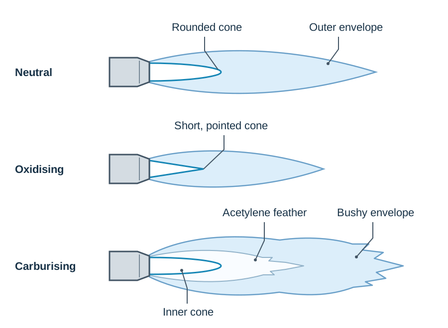
Quick Flame Summary: Neutral = 1:1, no feather, mild steel; Oxidising = extra oxygen, pointed cone, brass and bronze; Carburising = extra acetylene, white feather, aluminium and hard-facing.
Fillers and Fluxes in Gas Welding
In gas welding, a hand-held filler rod supplies extra metal to fill and reinforce the seam. For mild steel, a copper-coated mild steel rod containing manganese and silicon deoxidisers is used; the copper wash simply stops the bare wire rusting in workshop storage.
A flux is a chemical paste or powder applied to the joint. It performs three vital functions:
- It dissolves and breaks down surface oxide films on the heated metal.
- It floats the dissolved oxides out of the pool as a light, fusible slag.
- It seals the molten surface against fresh atmospheric oxygen attack.
Mild steel needs no flux because iron oxide melts below the melting point of steel, so it liquefies and floats off on its own. In contrast, aluminium welding demands flux because aluminium oxide () melts at roughly 2050 °C while aluminium melts at 660 °C; without an active chloride/fluoride flux, the solid oxide skin traps the pool and prevents fusion. Cast iron, brass, and stainless steel also require flux. Residues must be scrubbed off after welding because flux salts are corrosive.
Lighting, Operation, and Safety Sequences
- Stand cylinders upright, chained securely. Crack each cylinder valve briefly to clear dust, then attach regulators.
- Attach blue hose to oxygen (right-hand thread) and red hose to acetylene (left-hand thread, notched nut).
- Open cylinder valves slowly, set regulator pressures, and check joints with soapy water (never a naked flame).
- Lighting: Open the blowpipe acetylene valve slightly and ignite using a flint spark lighter (never matches). The initial flame is yellow and sooty.
- Open the oxygen valve slowly until the ragged feather disappears into a rounded inner cone—the neutral flame.
- Shutting down: Close the blowpipe acetylene valve first, then the oxygen valve. This extinguishes the flame cleanly and prevents soot or internal pops. Close cylinder valves and bleed hoses.
Backfire: The flame momentarily pops back into the nozzle tip and relights, caused by an overheated nozzle, touching the tip against the plate, or insufficient gas pressure. Flashback: The flame burns backwards through the blowpipe and along the hoses towards the cylinders with a shrill squeal. Close the oxygen blowpipe valve immediately, then the acetylene valve. Sintered flashback arrestors prevent the flame reaching the cylinder.
Electricity in Arc Welding: Transformers, AC, DC, and Polarity
An electric arc generates temperatures over 3500 °C when electric current ionises a gas gap between an electrode and the workpiece. The arc demands a safe open-circuit striking voltage (50 V to 80 V) and high current (50 A to 300+ A).
The Welding Transformer
A welding set uses a step-down transformer to convert 230 V single-phase mains supply into high welding currents. It consists of primary and secondary copper windings wrapped around a soft-iron core. The core is constructed from thin insulated laminations to break up circulating currents and minimise eddy-current heat losses.
For an ideal transformer:
where are voltages, are turns, and are currents. Stepping down mains voltage by a factor of 4 steps secondary current up by a factor of 4, producing the amperage needed to fuse heavy steel.
Alternating Current (AC) versus Direct Current (DC)
- Alternating current (AC): Current changes direction continuously (50 Hz). Heat divides roughly equally between electrode and workpiece. Standard for general MMA welding with rutile electrodes and essential for TIG welding aluminium.
- Direct current (DC): Flows continuously in one direction, converted from transformer AC using a semiconductor rectifier. Delivers a smoother, quieter arc.
- DCEN (Direct Current Electrode Negative / Straight Polarity): The electrode connects to negative and the workpiece to positive. In TIG welding of steel, this directs roughly 70% of the arc heat into the workpiece, giving deep penetration while keeping the tungsten electrode cool.
- DCEP (Direct Current Electrode Positive / Reverse Polarity): The electrode connects to the positive terminal. This is the standard polarity setting for continuous-wire MIG welding and basic low-hydrogen MMA electrodes.
Manual Metal Arc (MMA) Welding and Downhand Butt Joint Procedure
Manual Metal Arc (MMA) welding strikes an arc between a flux-covered consumable electrode and the workpiece, melting both into a single puddle.
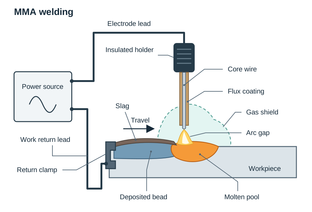
Functions of the Electrode Flux Coating
- Gaseous shielding: Cellulose and carbonate minerals decompose in the arc, generating carbon dioxide and carbon monoxide gas clouds that push away ambient oxygen and nitrogen. Electrodes must be dry; moisture releases hydrogen, causing porosity and cracking.
- Slag blanket: Melted minerals float to the surface of the molten steel pool because slag is less dense. This crust shields the cooling bead from air and slows the cooling rate, preventing hard, brittle martensite from forming.
- Arc stabilisation: Easily ionised chemicals in the coating lower the electrical resistance across the arc gap, making arc striking reliable and preventing flame-outs.
- Deoxidation and alloying: Manganese and silicon in the flux scavenge dissolved oxygen and replace elements lost to vaporisation.
Electrode Coding (AWS System)
In the common specification code E6013:
- E: Arc welding consumable electrode.
- 60: Minimum tensile strength of deposited weld metal ().
- 1: Suitable for welding in all positions (flat, horizontal, vertical, overhead).
- 3: Coating composition and current type: indicates a rutile (titanium dioxide) coating operating on AC or DC.
Coating types: Rutile provides smooth beads, easy striking, and soft arc action. Basic (low-hydrogen) coatings contain calcium carbonate and produce tough, crack-resistant joints in heavy structural steel; they must be kept in heated drying ovens to eliminate moisture. Cellulosic coatings produce high gas volume and deep penetration on overland pipelines.
Ordered Procedure: Downhand Butt Weld on 8 mm Mild Steel
- Edge preparation: Bevel the plate edges with an angle grinder (or oxy-fuel torch tilted at an angle) to form a single-V with a 60° included angle, a 1.5 mm root face, and a 2 mm root gap. Reason: Thick plate with square edges blocks arc penetration, leaving an unfused root.
- Surface cleaning: Grind back mill scale, rust, paint, and oil 20 mm either side of the joint. Reason: Surface hydrocarbons cause gas porosity and hydrogen cracking.
- Tacking: Align plates on the bench and apply short tack welds at each end. Reason: Restrains thermal expansion and prevents the root gap closing during welding.
- Current setting: Fit a 3.2 mm E6013 electrode into the insulated holder, clamp the work return lead to bare metal, and set the transformer to roughly 120–130 A (using the 40 A per mm diameter guideline). Reason: Provides sufficient heat for root fusion without burning holes through the plates.
- PPE check: Wear leather gauntlets, protective apron, and a headshield with a shade 10–11 lens. Reason: Protects skin from spatter and shields eyes against ultraviolet radiation.
- Root pass: Strike the arc with a light scratch and hold a 3 mm arc length tilted 70°–80° in the direction of travel. Deposit the root run along the gap, watching the pool so the root faces fuse completely. Reason: Guarantees structural strength through the base of the seam.
- Slag removal: Allow the bead to cool to dull red, chip the brittle slag blanket off with a chipping hammer, and brush vigorously with a wire brush. Reason: Any residual slag left behind becomes trapped as an internal slag inclusion defect in the next run.
- Filler and capping runs: Deposit intermediate filler passes and complete the joint with a weaving capping run slightly proud of the plate surface. Clean and inspect. Reason: Rebuilds plate thickness and verifies absence of surface undercut.
Inert Gas Shielded Arc Welding: TIG and MIG/MAG
Inert gas processes replace solid mineral flux with a protective cylinder gas stream, producing clean, slag-free deposits.
Tungsten Inert Gas (TIG / GTAW)
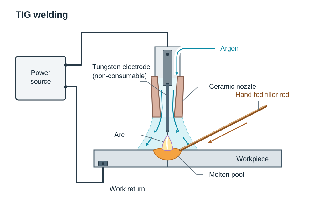
TIG welding sustains an arc between a non-consumable tungsten electrode and the workpiece inside a shielding envelope of pure argon. Tungsten's melting point (3422 °C) allows it to maintain the arc without melting. Any required filler metal is fed by hand into the leading edge of the weld pool.
- Welding aluminium with AC: Aluminium forms a tough surface skin of aluminium oxide () that melts at roughly 2050 °C, while aluminium melts at 660 °C. TIG welding aluminium requires Alternating Current (AC). During the positive half-cycle (electrode positive), electrons flow from the plate, blasting away the refractory oxide skin by cathodic cleaning. During the negative half-cycle (electrode negative), electrons bombard the workpiece, providing deep melting penetration.
- Welding steel and stainless steel: Carried out on DCEN (straight polarity) to concentrate arc heat in the joint while keeping the tungsten electrode cool.
- Applications & limits: Delivers precise, spatter-free, aesthetic welds on thin stainless drums, bicycle frames, and pipework. However, it has slow deposition rates, high equipment costs, and requires high manual skill.
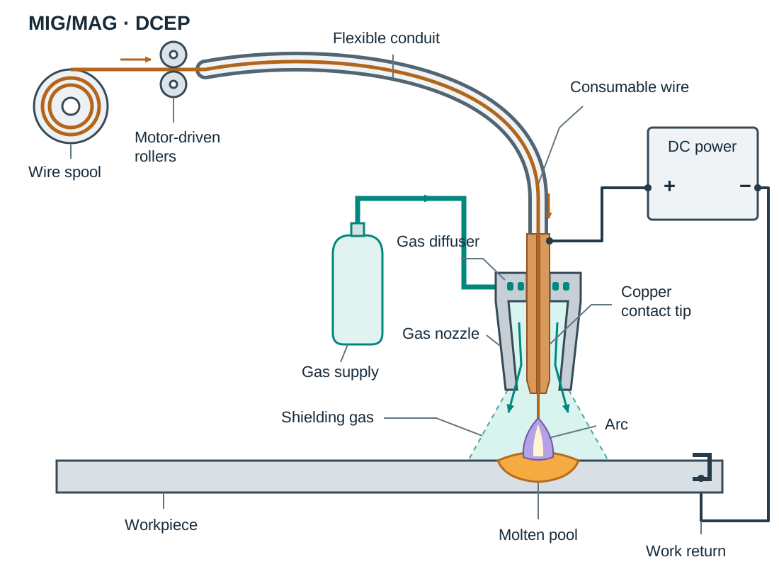
Metal Inert Gas (MIG / GMAW) and MAG
MIG is a semi-automatic process. A motorised drive unit continuously feeds a bare, consumable wire electrode from a reel through a welding torch. Depressing the torch trigger establishes the arc and gas flow simultaneously.
- MIG vs MAG: True MIG uses inert gas (pure argon or helium) for non-ferrous metals like aluminium. When welding mild steel, an active gas blend containing carbon dioxide ( or ) is used to stabilise the arc and deepen penetration; this process is formally designated MAG (Metal Active Gas).
- Applications & limits: MIG/MAG is fast, continuous, produces zero slag, and welds thin sheet steel (down to 0.8 mm) without burn-through, making it the dominant process in vehicle body repair and sheet fabrication. However, the equipment is bulky and shielding gas is easily blown away by draughts, making it poor for outdoor site work.
What Your Exam Diagrams Must Show
- TIG sketch: Tungsten electrode, ceramic gas nozzle, argon gas envelope, separate filler rod fed by hand, electric arc, molten pool, workpiece, and work return lead.
- MIG sketch: Spool of wire, motor drive feed rollers, flexible cable conduit, welding gun with copper contact tip, gas diffuser nozzle, shielding gas shroud, arc, molten pool, and workpiece.
Automated Arc Processes: Submerged Arc (SAW) and Electro-Slag (ESW)
Heavy manufacturing relies on fully automated systems to weld thick plate sections rapidly and consistently.
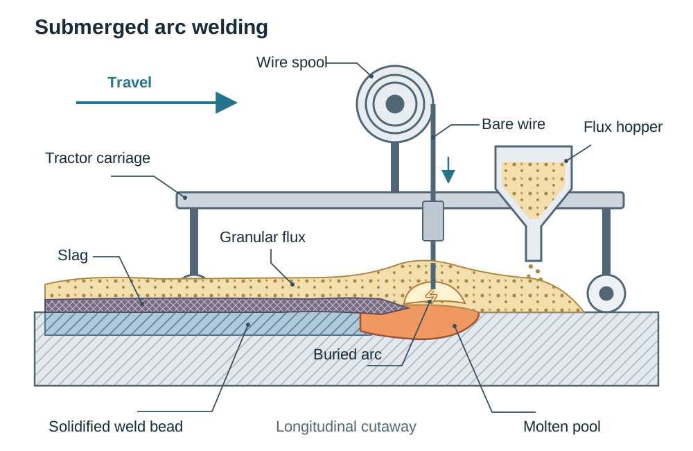
Submerged Arc Welding (SAW)
In Submerged Arc Welding, a tractor unit travels along a seam while a bare consumable wire feeds automatically from a coil. A hopper deposits a layer of loose granular flux directly over the joint, burying the electric arc and molten pool completely.
- Main features: Because the arc is submerged beneath the flux blanket, there is no visible arc glare, spatter, or smoke; operators in the surrounding workshop do not need dark welding shields. Unfused granular flux is vacuumed back into the hopper for reuse, while fused flux cools into a brittle slag crust that detaches easily.
- Applications & limits: SAW provides deep penetration and high deposition rates for long straight seams in wind turbine towers, bridge girders, ship deck plates, and large pressure vessels. Because loose granular flux must stay in position over the seam, SAW is strictly limited to the flat (downhand) or horizontal positions.
- Sketch checklist: Wire spool, bare wire electrode, flux hopper depositing granular flux blanket, buried electric arc, molten pool beneath slag, solidified weld bead, and tractor carriage.
Electro-Slag Welding (ESW)
Electro-slag welding joins very thick vertical steel plates (from 25 mm to over 300 mm thick) in a single pass.
- Operating principle: Plates stand upright with an open gap. Water-cooled copper shoes clamp both faces to form a vertical mould. Granular flux is added and an electric arc strikes initially to melt it. Once a conductive bath of molten slag builds up, the electric arc extinguishes completely. From this point, heat is generated purely by electrical resistance as current passes through the molten slag bath. Consumable guide tubes feed wire into the bath, where wire and plate edges melt together and solidify from the bottom up while the copper shoes index upwards.
- Critical limitation: ESW can only be performed in the vertical position, because gravity is required to hold the molten slag pool inside the mould formed by the copper shoes. Used for heavy press frames, rolling mill housings, and shipyard construction.
Electrical Resistance Welding: Spot, Seam, and Projection
Resistance welding processes generate heat through the electrical resistance of clamped workpieces according to Joule's law of electric heating:
where is heat in joules (J), is current in amperes (A), is electrical interface resistance in ohms (Ω), and is current duration in seconds (s).
Because the electrical resistance where the two overlapping sheets touch each other is much higher than that of solid copper or steel, passing an enormous current (8000–12 000 A) at low voltage (2–10 V) for a fraction of a second generates intense heat at the contact point. This melts a localised weld nugget without filler rods, flux, or shielding gas.
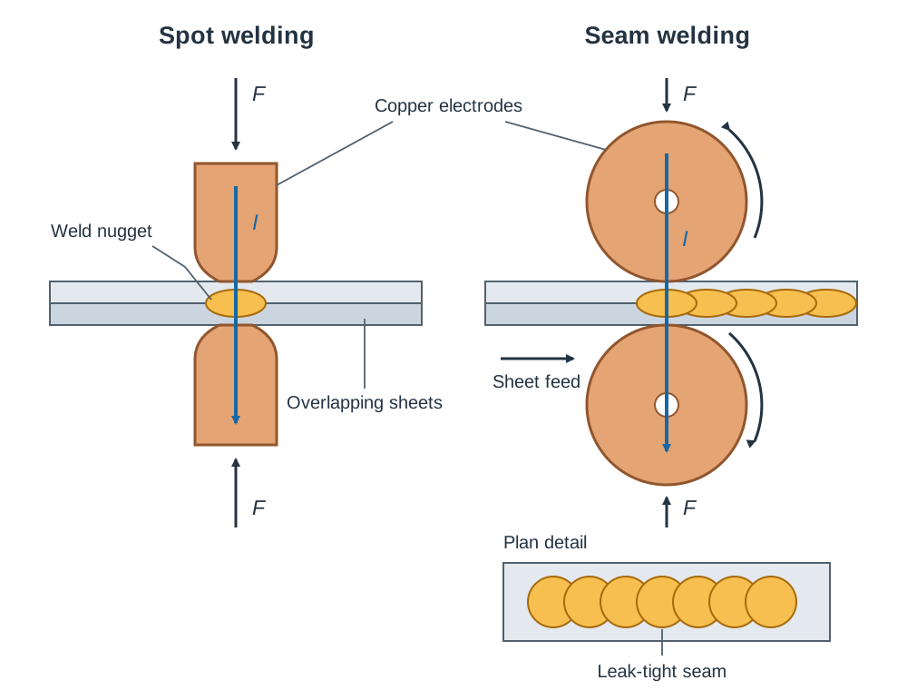
Resistance Spot Welding
- Electrode design: Domed, water-cooled copper alloy cylindrical electrodes.
- Operating cycle: Sheets are clamped under mechanical/pneumatic force; a high-current pulse passes for 0.1–0.5 s, creating a molten nugget; current cuts off while pressure is held to forge the solidifying metal; electrodes release.
- Applications: Automotive sheet assemblies, brackets, and cabinets.
Resistance Seam Welding
- Electrode design: Pointed tips are replaced by motor-driven rotating copper wheel electrodes.
- Operating cycle: Workpieces feed between the rotating wheels under constant pressure while current passes in timed, rapid pulses.
- Characteristics: Each current pulse produces an individual nugget. Because the wheels roll continuously, successive nuggets overlap by 25%–50%, producing a continuous, leak-tight seam.
- Applications: Automotive fuel tanks, domestic central-heating radiators, chemical storage drums, and tin cans.
Projection Welding
Small raised dimples (projections) are pressed into one sheet before assembly. The components are clamped between flat copper platens and current is switched on. Because current can only flow through the raised points, heat concentrates there, forming multiple weld nuggets in a single operation. This eliminates individual spot alignment and extends electrode life. Used for securing threaded studs, nuts, and brackets to vehicle body panels.
Butt and Flash Welding
Two bar or pipe ends are clamped in copper jaws and pressed together while heavy current flows. Contact resistance heats the ends to a plastic state; flashing burns away surface impurities, and the ends are forged together under axial pressure, forming an upset ring. Used for joining bandsaw blades, chain links, and rail sections.
Welding of Plastics, Weldability, and Distortion Control
Welding is strictly limited to thermoplastics (polyethylene, polypropylene, PVC, acrylic). Thermoplastics consist of linear polymer chains held by weak secondary bonds; heat softens and melts the material, allowing chains to interweave and fuse upon cooling. Thermosetting plastics (epoxy, polyurethane, phenolic resin) possess permanent three-dimensional covalent cross-links; applying heat degrades and chars them without melting, making welding impossible.
Plastics Welding Methods
- Hot gas welding: A hot-air gun directs clean air or nitrogen heated to 200–300 °C into a bevelled joint and onto a matching thermoplastic filler rod, fusing them under manual pressure. Used for PVC ducting and chemical storage tanks.
- Heated tool (butt fusion) welding: Pipe ends (such as polyethylene gas and water mains) are squared and pressed against an electrically heated PTFE plate. Once a molten bead forms, the plate retracts and the pipe ends are clamped together until cool.
- Ultrasonic welding: High-frequency mechanical vibrations (20–40 kHz) transmit through a vibrating horn (sonotrode), creating interfacial friction that melts plastic parts in under a second. Used for mass-producing small electrical housings and toys.
Weldability and Heat Treatment
Weldability describes how readily a metal can be joined without cracking.
- Mild steel (0.15%–0.25% C): Excellent weldability. Its low carbon content prevents the formation of hard, brittle martensite during rapid cooling, keeping the joint tough.
- Medium- and high-carbon steels: Poor weldability. Rapid cooling quenches the heat-affected zone, transforming austenite into brittle martensite, causing cracks. These steels require preheating (150–300 °C) to slow cooling, followed by post-heating (stress relief or tempering) to relieve contraction stresses.
- Cast iron: Highly brittle; must always be preheated and cooled very slowly to prevent thermal shock fractures.
Distortion Control
Because weld metal contracts as it cools from liquid to solid, plates tend to pull out of alignment. Distortion is minimised by:
- Tack welding along the seam before full welding.
- Clamping workpieces firmly in jigs and fixtures.
- Backstep welding: Depositing short runs in the opposite direction to overall travel so expansion and contraction stresses balance out.
- Balanced welding: Alternating runs on opposing sides of a double-V joint.
- Preheating the entire assembly so expansion and contraction occur uniformly.
Weld Defects, Safety Precautions, and Process Selection
Fabrication quality demands identifying defects, enforcing workshop safety, and selecting the correct process for a given engineering application.
Common Weld Defects
| Defect | Visual Appearance | Primary Cause | Prevention |
|---|---|---|---|
| Porosity | Cavities or pinholes on or within the bead | Moisture, rust, grease on the plate; damp electrode; loss of shielding gas | Clean joint thoroughly; store basic electrodes in drying ovens; ensure adequate gas flow |
| Slag inclusion | Non-metallic slag trapped inside the weld | Incomplete chipping of slag between passes; incorrect electrode angle | Chip and wire-brush between every run; maintain correct arc angle |
| Lack of penetration | Joint root not fused | Square edges without bevel; root gap too narrow; travel speed too fast | Prepare single-V with correct gap; slow travel; increase current |
| Undercut | Groove melted into plate along the weld toe | Current set too high; arc length held too long | Reduce amperage; maintain arc length equal to core wire diameter |
Workshop Safety Precautions
- Optical radiation ('arc-eye'): Arc welding emits intense ultraviolet (UV) and infrared (IR) radiation. Unprotected UV exposure burns the cornea, causing painful arc-eye. Welders must wear a helmet with a certified filter lens (shade 10–11 for MMA; 11–12 for TIG). Oxy-acetylene requires tinted gas goggles (shade 4–6). Surrounding bays must be screened with fire-retardant curtains.
- Oxygen handling: Never allow oil or grease near oxygen cylinders, valves, or regulators; oil ignites spontaneously in high-pressure oxygen. Never use oxygen to blow dust off clothing.
- Toxic fumes: Arcs vaporise surface coatings. Welding galvanised (zinc-plated) steel creates toxic zinc oxide fumes causing metal fume fever. Local exhaust ventilation (LEV) hoods are mandatory.
- Electrical safety: Arc welding power units must be properly earthed. Operators and floors must remain completely dry, as dampness reduces body resistance and makes 50–80 V open-circuit voltage dangerous.
Process Selection Table
| Application | Recommended Process | Key Justification Reasons |
|---|---|---|
| Classic car body panel (0.9 mm mild steel) | MIG (MAG) | 1. Welds thin gauge sheet without burn-through.<br>2. Fast, continuous wire feed produces clean, spatter-free joints. |
| Aluminium scooter frame (2.0 mm tube) | AC TIG | 1. Cathodic cleaning on AC removes the tough oxide film.<br>2. Precise heat control produces neat, slag-free structural joints. |
| Stainless steel food processing drum | TIG | 1. Inert gas shield leaves zero slag to contaminate food vessels.<br>2. High precision and aesthetic quality on corrosion-resistant sheet. |
| Wind turbine tower cylindrical seam | SAW | 1. Fully automated tractor system ideal for long continuous runs.<br>2. Delivers deep penetration and high deposition rates on heavy plate. |
| Domestic central heating radiator | Resistance seam welding | 1. Continuous overlapping weld nuggets produce a leak-tight seal.<br>2. Rapid, automated process requiring no filler rod or flux. |
| Motor car chassis body shell | Robotic resistance spot welding | 1. High speed and repeatability across thousands of spot joints.<br>2. Eliminates consumables and removes operators from hazard zones. |
Key terms
- Fusion Welding
- Joining materials by melting the parent metal contact surfaces together, with or without added filler, creating a solid continuous joint upon cooling.
- Heat-Affected Zone (HAZ)
- The region of parent metal directly adjacent to the weld that did not melt, but whose grain structure and mechanical properties were altered by welding heat.
- Neutral Flame
- An oxy-acetylene flame produced by a balanced 1:1 oxygen-to-acetylene mixture (~3250 °C) with a rounded inner cone; used for mild steel because it neither oxidises nor adds carbon.
- Dissolved Acetylene
- Acetylene gas dissolved under pressure in liquid acetone within a porous mass inside a maroon cylinder to prevent explosive decomposition above 1 bar.
- Flashback Arrestor
- A safety device fitted to gas welding regulators and blowpipes containing a sintered stainless-steel flame trap and non-return valve that halts upstream flame propagation.
- Step-Down Transformer
- An electrical device that uses mutual induction between coils on a laminated soft-iron core to reduce mains voltage to safe working levels while increasing output current.
- DCEN (Straight Polarity)
- Direct current connection with the electrode negative and workpiece positive, directing roughly 70% of arc heat into the work for deep penetration.
- Cathodic Cleaning
- The removal of refractory surface oxides (such as aluminium oxide) caused by positive ion bombardment during the electrode-positive half-cycle of AC TIG welding.
- Rutile Electrode
- An MMA welding electrode coated with titanium dioxide minerals, providing smooth arc striking, stable downhand operation, and easily detached slag.
- Weld Nugget
- The small lens-shaped zone of fused and re-solidified metal formed between overlapping sheets in resistance spot, seam, or projection welding.
- Submerged Arc Welding (SAW)
- An automated arc process where a continuous bare wire melts into a joint beneath a thick, protective blanket of loose granular mineral flux.
- Electro-Slag Welding (ESW)
- An automated vertical welding process for thick plates that generates heat by passing electric current through an electrically conductive pool of molten slag.
- Arc-Eye
- Painful acute inflammation of the cornea caused by exposure to ultraviolet radiation emitted by an electric welding arc.
- Weldability
- The relative ease with which a metal can be welded to produce a sound, crack-free joint that fulfills its structural service requirements.
Check yourself
Why must an active flux be used when gas welding aluminium, whereas mild steel requires none?
Aluminium oxide () melts at roughly 2050 °C, far above aluminium's 660 °C melting point, forming a solid skin that blocks fusion unless dissolved by flux. Iron oxide melts below steel's melting point and floats off naturally.
What is the distinction between backfire and flashback in an oxy-acetylene blowpipe?
A backfire is a momentary pop where the flame retreats into the nozzle tip and relights. A flashback is an internal burning of the flame back through the blowpipe and along the hoses towards the cylinders.
Why is pure acetylene gas never compressed on its own above 1 bar gauge pressure?
Acetylene becomes chemically unstable and can explosively decompose above 1 bar; it must be dissolved in liquid acetone inside a porous mass within the cylinder.
Why is TIG welding preferred over MMA welding for fabricating a stainless steel pressure vessel?
TIG produces high-purity, slag-free, aesthetically clean welds with precise heat control, eliminating the risk of slag inclusions that could leak under pressure.
State two methods used in sheet fabrication to control welding distortion.
Tack welding along the seam to maintain alignment, and using backstep welding so that contraction forces from short runs oppose and cancel each other out.
Why is Electro-Slag Welding (ESW) strictly confined to the vertical welding position?
The process depends on gravity to contain the deep, electrically conductive molten slag bath and liquid metal pool inside the cavity between the water-cooled copper retaining shoes.