
Technical abbreviations form the standard shorthand of modern engineering practice. On working drawings, welding specifications, material lists, and machine control panels, they convey critical manufacturing and safety data without cluttering prints or causing costly misunderstandings in the workshop. In Leaving Certificate Higher Level Engineering, abbreviations appear across the short-answer section and within specialised topics including metallurgy, polymers, metrology, and machining. When explaining an abbreviation in an exam, always give two things: the full title spelled accurately, followed by one clear sentence stating what it does or where it is used in engineering practice.
Working Drawing Conventions and Geometry Abbreviations
Engineering drawings follow international conventions so that components can be manufactured accurately in any workshop without ambiguity. Unless otherwise stated on the title block, all linear dimensions are in millimetres (mm). Abbreviations are written in capital letters without punctuation marks. Where a symbol indicates geometry (such as for diameter or for radius), it precedes the numerical value (for example, or ). General manufacturing notes follow the value (for example, ).
| Abbreviation | Full Title | What It Tells the Machinist |
|---|---|---|
| / DIA | Diameter | Circular dimension across the centre of a cylindrical hole, shaft, or disc (e.g. ). Never confuse with radius . |
| / RAD | Radius | Distance from the centre point to the curved edge of an arc, bend, or corner fillet (e.g. ). |
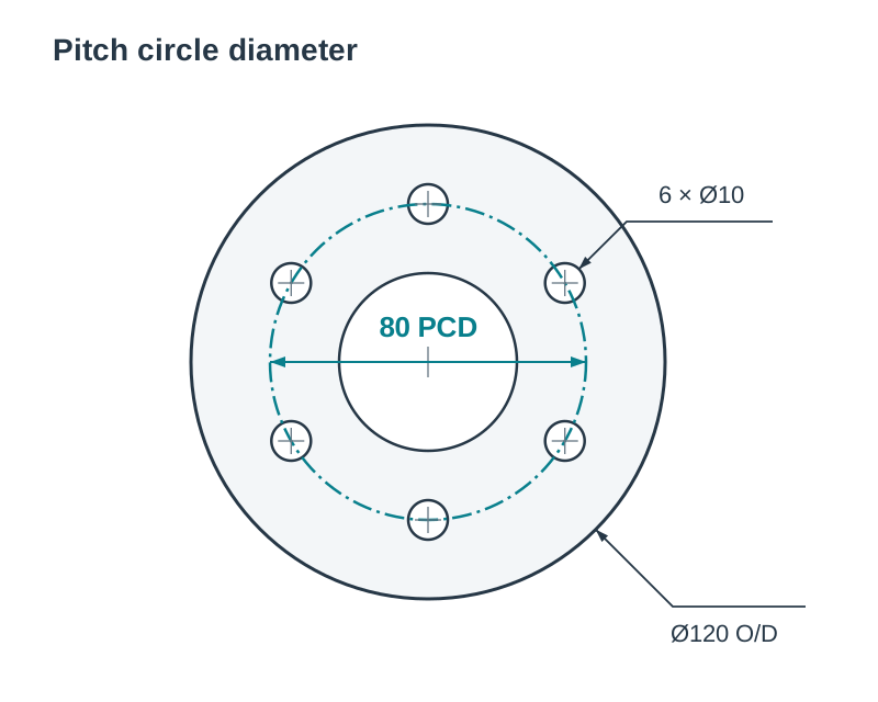
| PCD | Pitch Circle Diameter | Diameter of an imaginary circular path passing through the exact centres of a pattern of holes or bolts (e.g. ). |
| A/F | Across Flats | Distance between two opposite parallel flat faces on a hexagonal nut or bolt head, or on a square drive. It dictates the required spanner size. |
| CL | Centre Line | Axis of symmetry of a part, drawn as an alternating long-and-short chain line. |
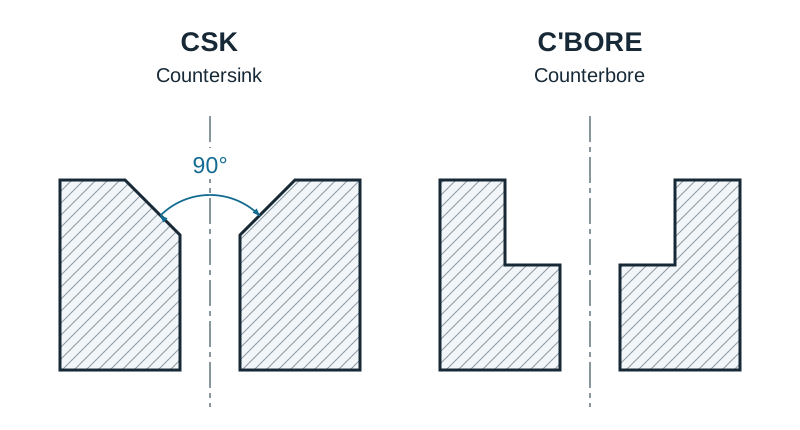
| CSK | Countersink | Conical enlargement at the mouth of a hole (typically included angle) allowing flat-head screws to sit flush with the surface. |
| C'BORE | Counterbore | Flat-bottomed cylindrical enlargement at the mouth of a hole, designed to recess the cylindrical head of a socket cap screw. |
| CRS | Centres | Direct centre-to-centre distance between two holes, pins, or shafts. |
| CHAM | Chamfer | Bevelled edge (commonly machined at ) that removes sharp corners, prevents burrs, and eases assembly. |
| MATL | Material | Specifies the required stock metal or polymer from which the component must be machined. |
| O/D & I/D | Outside / Inside Diameter | External and internal diameters of hollow cylinders, tubing, or bearing bushes. |
| THK | Thickness | The gauge or plate thickness of sheet metal or flat stock. |
| SQ & HEX | Square / Hexagon | Identifies a square cross-section () or regular six-sided geometric profile. |
| NTS | Not to Scale | Indicates that a drawn feature does not match the printed scale and must be machined strictly to the written dimension. |
| TYP | Typical | Signifies that a specific dimension or detail applies to all identical features unless marked otherwise. |
| U/C | Undercut | A recessed groove cut into a shoulder or thread runout to allow mating parts to sit flush or cutting tools to clear. |
| SF | Spot Face | A shallow, flat-machined circular pad around a hole on a rough casting to provide a true bearing surface for a bolt head or washer. |
| BOM | Bill of Materials | An itemised schedule on an assembly drawing listing part numbers, descriptions, quantities, and material specs. |
Screw Threads and Limits and Fits
Screw threads and fits are defined by standardised callouts on technical drawings to ensure parts assemble correctly.
Screw Thread Callouts
- M10 1.5: M specifies an ISO metric thread profile ( included angle). 10 is the nominal outside (major) diameter in mm. 1.5 is the pitch in mm (the distance from one thread crest to the next, measured parallel to the axis). If no pitch is listed (e.g. M10), the standard coarse pitch series applies.
- LH (Left-Hand Thread): The thread tightens anticlockwise. Used where normal rotational motion would undo a standard right-hand thread, such as the left pedal spindle on a bicycle or one end of an adjustable turnbuckle.
- 2 START (Multi-Start Thread): Two independent helical grooves cut along the same cylinder. While pitch remains the crest-to-crest distance, the lead (axial advance per full revolution) equals . A 2-start thread with a pitch advances per turn, giving rapid axial motion in vice screws and valve stems.
- TPI (Threads Per Inch): Imperial thread specification stating the number of crests per inch (used in BSW and UNF threads).
Limits, Fits, and Gauges
Limits and fits are written using the ISO hole-basis system, which enables interchangeable manufacture by specifying allowed variations from nominal size.
- H7/g6: A standard precision sliding clearance fit. Capital letters indicate internal features (H = hole) and lowercase letters indicate external features (g = shaft). In the hole-basis system, the letter H fixes the lower deviation at zero, meaning the minimum hole size equals nominal diameter. Numbers (7 and 6) denote the IT (International Tolerance) grade; smaller numbers indicate tighter tolerances.
- GO / NO-GO Gauges: Workshop limit gauges used to check production parts rapidly without taking direct measurements. For a hole, the GO plug is ground to the minimum allowable size and must enter cleanly. The NO-GO plug is ground to the maximum allowable size and must not enter. If GO enters and NO-GO does not, the feature falls within its specified tolerance band.
- Standards Bodies: ISO (International Organization for Standardization) produces worldwide engineering limits and fits; NSAI (National Standards Authority of Ireland) oversees Irish standards (marked I.S.); EN and BS denote European Norms and British Standards.
Metallurgy: Chemical Symbols, Crystal Lattices, and Equilibrium Phases
You are expected to know the chemical symbols of common workshop metals, their ores, and the elements used in alloys. Several elemental symbols originate from historical Latin names or ore minerals:
| Metal | Symbol | Origin of Symbol | Common Workshop Application |
|---|---|---|---|
| Iron | Fe | Latin ferrum | Base element in plain carbon steels and cast irons |
| Copper | Cu | Latin cuprum | Electrical wiring, heat exchangers; alloyed to make brass and bronze |
| Tin | Sn | Latin stannum | Alloyed with copper to form bronze; protective tinplate on steel |
| Lead | Pb | Latin plumbum | Radiation shielding, heavy balance weights, plumbing flashings |
| Tungsten | W | German wolfram (ore wolframite) | Non-consumable TIG welding electrodes; heavy alloying addition in HSS cutting tools |
| Zinc | Zn | German Zink | Galvanised protective dip coatings for mild steel; die-casting alloy base |
| Aluminium | Al | Latin alumen | Lightweight structural tubing, cast engine blocks, aircraft skin panels |
| Silver / Gold | Ag / Au | Latin argentum / aurum | High-conductivity electrical contacts and fine jewellery |
Common alloying elements in tool steels include Manganese (Mn), Chromium (Cr), Nickel (Ni), Molybdenum (Mo), and Vanadium (V). Note that engineering alloys do not have unique chemical symbols; brass is designated Cu-Zn and bronze is designated Cu-Sn.
Crystal Lattices and Phase Transformations
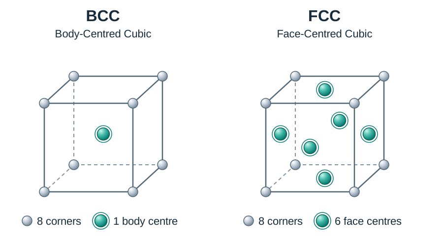
- BCC (Body-Centred Cubic): A unit cell with an atom at each corner of the cube and one atom at the centre of the cube. BCC is the structure of (alpha) ferrite, the soft, ductile form of iron that exists below the critical range (up to in pure iron), as well as tungsten and chromium. BCC metals tend to be strong and hard with moderate cold ductility.
- FCC (Face-Centred Cubic): A unit cell with an atom at each corner and one in the centre of every cube face. Found in copper, aluminium, and (gamma) austenite (the solid solution of carbon in iron formed when steel is heated above its upper critical line). FCC metals are ductile and easily deformed cold.
- HCP (Hexagonal Close-Packed): A close-packed hexagonal unit cell found in zinc and magnesium, typically exhibiting limited cold formability.
- UCT and LCT: Upper and Lower Critical Temperatures on the iron-carbon equilibrium diagram. The LCT sits at across the steel portion of the diagram. When hardening steel, the component must be heated above its UCT into the austenite range before quenching.
- (Cementite): Iron carbide containing carbon by mass; extremely hard and brittle.
- Pearlite: A fine lamellar (layered) mechanical mixture of -ferrite and cementite () formed on slow cooling through . A carbon steel forms pearlite.
- Martensite: A very hard, brittle, needle-like microstructure produced when austenite is quenched rapidly in water or oil, trapping carbon atoms in the lattice. It must always be tempered to relieve internal stresses and restore toughness.
Polymers: Thermoplastics, Thermosets, and Composites
Polymer designations rely on standardized acronyms across materials testing and recycling standards. In examinations, identify whether the material is a thermoplastic (linear or branched molecular chains that soften on heating and can be repeatedly reshaped and recycled) or a thermoset (heavily cross-linked polymer network that chars and decomposes under heat rather than melting).
Thermoplastics
- PVC (Polyvinyl Chloride): Rigid unplasticised PVC (uPVC) is used for external rainwater downpipes and window framing. Adding plasticisers yields flexible PVC for electrical wire insulation.
- PTFE (Polytetrafluoroethylene): Sold under the trade name Teflon. Features an exceptionally low coefficient of friction, high operating temperature resistance, and extreme chemical inertness. Used for unlubricated dry bearings, chemical valve seals, and thread-sealing plumber's tape.
- LDPE (Low-Density Polyethylene): Flexible thermoplastic with branched chains; used for squeeze bottles, wash bottles, and plastic packaging films.
- HDPE (High-Density Polyethylene): Denser, more rigid polymer with tightly packed linear chains; used for chemical drums, bottle crates, and domestic water service pipes.
- PP (Polypropylene): Tough thermoplastic with outstanding fatigue resistance in thin sections. Used for moulded toolboxes with integral living hinges, car bumpers, and domestic kettle casings.
- PS (Polystyrene): In rigid form, a hard, transparent, brittle polymer used for CD jewel cases; in expanded form (EPS), a lightweight closed-cell rigid foam used for protective packaging and thermal insulation.
- PMMA (Polymethyl Methacrylate): Known commercially as Perspex or acrylic. Hard, optically clear, weather-resistant polymer used for machine safety guards, signs, and vehicle light lenses.
- PA (Polyamide): Commonly called nylon. Tough, wear-resistant, and self-lubricating; widely machined or moulded into silent spur gears, bushes, and slide bearings that operate without oil.
- CA (Cellulose Acetate): A tough semi-synthetic plastic derived from plant cellulose, easily dyed and polished for spectacle frames and screwdriver handles.
- ABS (Acrylonitrile Butadiene Styrene): A tough, impact-resistant terpolymer used for protective safety helmets, power tool bodies, and 3D printer filaments.
Thermosetting Plastics and Composites
- PF (Phenol Formaldehyde): Known as Bakelite. Rigid, heat-resistant, and an excellent electrical insulator; used for domestic electrical plugs, switches, and saucepan handles.
- UP (Unsaturated Polyester): Liquid thermosetting resin that cross-links with the addition of a catalyst; acts as the binding matrix in glass-reinforced plastic.
- EP (Epoxy Resin): High-strength two-part thermoset combining resin and hardener. Possesses exceptional adhesion and low shrinkage; used in aerospace composites, high-performance structural adhesives, and PCB coatings.
- PUR / PU (Polyurethane): Synthesised as rigid thermal insulating foam, flexible furniture foam, or hard-wearing protective floor varnish.
- GRP (Glass-Reinforced Plastic): A composite material combining fine glass fibres embedded in a cured polyester or epoxy matrix; provides high tensile strength and light weight in boat hulls and car body panels.
Joining, Welding, and Electrical Safety
Fabrication processes and workshop electrical installations use specific shorthand to describe welding torches, electrode ratings, and electrical protection systems.
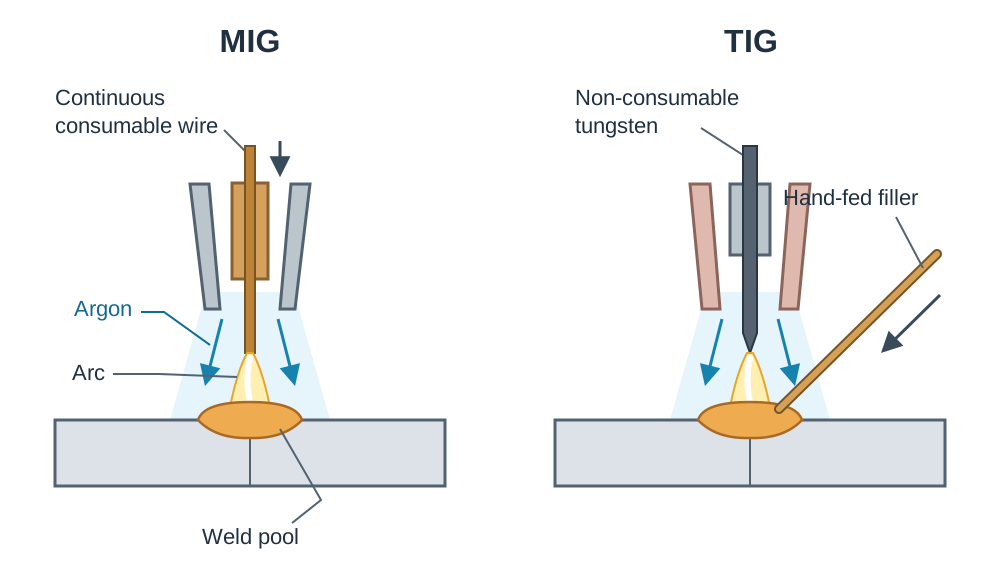
Welding and Fabrication Terminology
- MMA (Manual Metal Arc): Stick welding using a flux-coated consumable electrode. The arc melts the metallic core wire into the joint pool while the burning chemical flux generates a shielding gas curtain and deposits a protective slag layer over the cooling weld.
- MIG (Metal Inert Gas): Semi-automatic arc welding where a consumable bare wire electrode feeds continuously through the torch under a shield of inert gas (pure argon when welding aluminium).
- MAG (Metal Active Gas): Similar semi-automatic wire process, but uses an active shielding gas mix (such as argon mixed with carbon dioxide, ) to weld mild steel economically.
- TIG (Tungsten Inert Gas): Precision arc process that uses a non-consumable solid tungsten rod to maintain the arc under a pure argon shield. Filler wire is fed into the weld puddle manually. It produces high-quality, spatter-free joints in stainless steel, aluminium, and pipe root runs.
- AWS E6013: American Welding Society electrode classification for general mild steel fabrication:
- E = arc welding electrode;
- 60 = minimum tensile strength of the deposited weld metal, (approx. );
- 1 = suitable for welding in all positions (flat, horizontal, vertical, overhead);
- 3 = rutile flux coating, operable on alternating current (AC) or direct current (DC).
- HAZ (Heat-Affected Zone): The band of parent metal adjacent to the fusion joint that did not melt, but had its crystalline grain structure altered by the welding heat cycle. It must be checked for grain growth, hardening, and potential micro-cracking.
Electrical and Workshop Safety
Irish electrical mains supply operates at single phase (for standard wall sockets) and three phase (for heavy industrial machinery like lathes and milling machines), both at an alternating frequency of . Supply cables use standardised conductor colours: L (Live, brown), N (Neutral, blue), and E (Earth, green/yellow stripes).
- AC (Alternating Current): Current that reverses direction periodically — the Irish mains supply alternates 50 times per second (). Used for mains machinery and for AC arc welding sets.
- DC (Direct Current): Current that flows in one direction only, from a battery, rectifier or welding inverter; it need not be of constant magnitude, only of constant direction. DC gives a smoother, more stable welding arc, which is why TIG and MIG sets rectify the supply.
- RCD (Residual Current Device): A life-saving protection device that monitors the balance between current flowing in the live conductor and returning through the neutral. If an earth leakage current is detected (as low as ), it trips the power in milliseconds to prevent fatal electrocution.
- MCB (Miniature Circuit Breaker): An electromagnetic switch that trips when circuit current exceeds design rating, protecting workshop wiring against prolonged thermal overload and short circuits.
- PPE (Personal Protective Equipment): Safety gear worn to shield operators from hazards (e.g. shade-10 welding helmets, safety spectacles, leather gauntlets, and steel-toe boots).
- HSA (Health and Safety Authority): The statutory body in Ireland that enforces workplace safety regulations and publishes codes of practice.
- SDS (Safety Data Sheet): Manufacturer document listing chemical hazards, required PPE, safe ventilation, storage limits, and first-aid steps for solvents, resins, and cutting fluids.
- Fire Extinguisher Colour Codes: Water (Red label) for paper, wood, and textiles only (never on electrical or burning metal fires); (Black label) displaces oxygen to extinguish flammable liquid and live electrical fires without leaving conductive residue; Dry Powder (Blue label) versatile chemical powder safe on flammable gases, liquids, and electrical plant.
Metrology, Materials Testing, and Digital Manufacturing
Metrology and materials testing quantify mechanical limits, surface finish, and strength, while automated manufacturing links digital design directly to production.
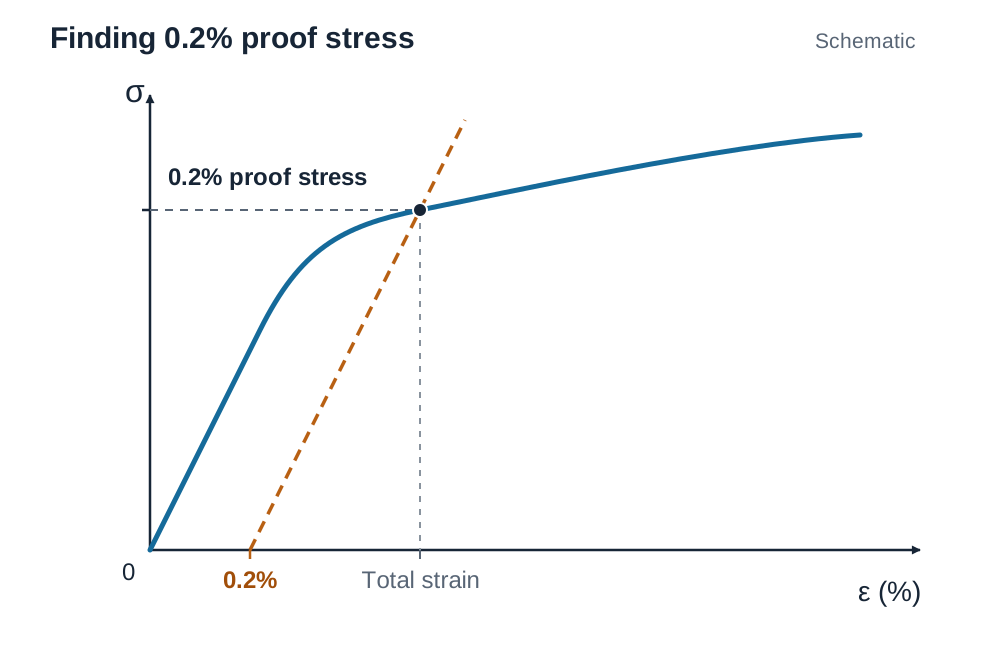
Materials Testing Symbols and Units
- (Stress): , the applied axial force divided by original cross-sectional area. Measured in (or ).
- (Strain): , the measured extension divided by the original gauge length. Strain has no units because it is a dimensionless ratio of lengths.
- (Young's Modulus): , the slope of the linear elastic region on a stress-strain graph, representing inherent material stiffness. Units are (or ; mild steel ).
- 0.2% Proof Stress: The stress that causes a non-proportional permanent elongation of of the gauge length after the load is released. Quoted for materials lacking a distinct yield point, such as aluminium alloys and high-carbon steels.
- UTS (Ultimate Tensile Strength): The maximum tensile load sustained by a specimen during a tensile test divided by its original cross-sectional area ().
- HB (Brinell Hardness Number): Hardness measured by pressing a hardened steel or carbide ball into the surface under a known load and measuring the indentation diameter — suited to soft metals and coarse-grained castings.
- HV (Vickers Hardness): Uses a square-based diamond pyramid indenter; suitable for both soft and very hard materials and for thin sections.
- HRC (Rockwell C): Uses a diamond cone indenter and reads hardness directly from the depth of penetration on the dial — quick, and used for hardened steels.
- NDT (Non-Destructive Testing): Inspection methods (dye penetrant, ultrasonic testing, magnetic particle inspection, radiography) used to detect internal cracks without damaging the part.
- (Roughness Average): Quantifies surface texture in micrometres () as the arithmetic average deviation of surface peaks and valleys from the mean centreline.
Machine Tools and Computer Integration
- HSS (High-Speed Steel): Heavily alloyed tool steel containing tungsten, chromium, vanadium, and carbon. It retains its cutting edge at red heat (known as red hardness) during heavy lathe and milling cuts.
- rpm (Revolutions Per Minute): Lathe or drill spindle rotational speed, calculated from cutting speed (in ) and diameter (in ):
- CAD, CAM, and CNC: CAD (Computer-Aided Design) creates 2D drawings and 3D digital solids. CAM (Computer-Aided Manufacture) generates toolpaths and calculates feed rates. CNC (Computer Numerical Control) uses microprocessors to drive machine axes automatically using programmed codes.
- G-Codes: Preparatory commands governing motion geometry: G00 (rapid positioning move without cutting), G01 (linear cutting feed), G02 / G03 (clockwise and anticlockwise circular interpolation), G90 (absolute programming from one fixed datum), and G91 (incremental programming relative to tool position).
- M-Codes: Miscellaneous commands governing auxiliary machine hardware: M03 (spindle forward/clockwise), M05 (spindle stop), M08 (coolant pump on), and M30 (end of program and rewind).
- CIM and FMS: CIM (Computer Integrated Manufacture) unifies design, machining, stock control, and robotics into one connected system. FMS (Flexible Manufacturing System) uses CNC machines and automated transfer handling to produce varied small-batch components with minimal setup changeover.
(Note: CAD, CAM and CNC appear in the computer-aided design and manufacture material of the syllabus (Appendix 1), which also covers control technology and robotics — check with your teacher which parts your class is taking).
Mechanism and Engine Shorthand
- IC Engine (Internal Combustion): Fuel is burned inside an enclosed cylinder to push a piston directly.
- TDC and BDC (Top / Bottom Dead Centre): The extreme highest and lowest points of piston travel in a cylinder. The stroke equals the linear distance between TDC and BDC (equal to twice the crank throw).
- SI and CI: SI (Spark Ignition) petrol engines ignite a fuel-air charge with a spark plug; CI (Compression Ignition) diesel engines compress air to high pressure and temperature so that injected diesel ignites spontaneously.
- OHC and OHV: OHC (Overhead Camshaft) mounts the camshaft above the valves in the cylinder head; OHV (Overhead Valve) mounts the camshaft inside the engine block, actuating valves via pushrods and rocker arms.
Key terms
- PCD
- Pitch Circle Diameter; the circular reference diameter passing through the exact centres of a radial pattern of holes.
- A/F
- Across Flats; the distance between two opposite parallel flat faces on a hexagonal nut or bolt head, which determines the required spanner size.
- PTFE
- Polytetrafluoroethylene; a slippery, chemically inert thermoplastic used for dry bearings, seals, and plumbing thread-seal tape.
- PVC
- Polyvinyl Chloride; a thermoplastic produced in rigid form (uPVC) for rainwater gutters and window profiles, or plasticised for electrical cable insulation.
- TIG
- Tungsten Inert Gas welding; an arc welding process using a non-consumable solid tungsten electrode shielded by an inert gas (such as pure argon).
- MIG
- Metal Inert Gas welding; a semi-automatic process that feeds a consumable bare wire electrode continuously through the torch under a protective gas shield.
- HAZ
- Heat-Affected Zone; the region of parent metal adjacent to a fusion weld that did not melt but underwent grain structure and property changes from welding heat.
- RCD
- Residual Current Device; a high-speed electrical protection device that trips when it detects an earth leakage current imbalance to prevent electrocution.
- MCB
- Miniature Circuit Breaker; an electromechanical switch that trips automatically during overcurrent or short circuits to protect wiring from overheating.
- HSS
- High-Speed Steel; a tool steel alloyed with tungsten, chromium, and vanadium that maintains red hardness at high cutting temperatures.
- UTS
- Ultimate Tensile Strength; the maximum tensile force sustained by a test specimen divided by its original cross-sectional area (measured in N/mm² or MPa).
- NDT
- Non-Destructive Testing; inspection methods (such as ultrasonic, dye penetrant, or X-ray radiography) used to find flaws without damaging the component.
- Ra
- Roughness Average; the metrology parameter measuring surface texture in micrometres (µm) as the arithmetic mean deviation from the centreline.
- H7/g6
- A standard ISO hole-basis tolerance designation for a precision sliding clearance fit between a unilateral hole (H7) and an undersized shaft (g6).
- TDC / BDC
- Top Dead Centre and Bottom Dead Centre; the uppermost and lowermost limits of piston travel within an internal combustion engine cylinder.
- CAD / CAM / CNC
- Computer-Aided Design (creating digital geometry), Computer-Aided Manufacture (generating toolpaths), and Computer Numerical Control (automated execution by machine tools).
Check yourself
What does PCD stand for on an engineering drawing, and what does it locate?
PCD stands for Pitch Circle Diameter. It specifies the circular path along which the centre points of a radial pattern of drilled holes or studs are positioned.
Give the correct elemental chemical symbols for tin, lead, and tungsten.
Tin is Sn, lead is Pb, and tungsten is W.
What is the primary operational difference between the electrodes used in MMA and TIG welding?
MMA uses a flux-coated consumable electrode that melts to deposit metal in the joint, whereas TIG uses a non-consumable tungsten rod that does not melt.
Explain what the drawing callout 24 A/F indicates on a hexagonal bolt head.
It stands for Across Flats, indicating a distance of 24 mm between opposite parallel flat faces, which dictates a 24 mm open-ended or ring spanner.
How does an RCD protect an operator in the workshop, and how does this differ from an MCB?
An RCD detects minute earth leakage current (tripping at 30 mA in milliseconds) to prevent electrocution, whereas an MCB trips under excessive current overload or short circuits to prevent cable fires.
A 40 mm diameter brass bar is turned on a lathe at a recommended cutting speed of 60 m/min. Calculate the required spindle rotational speed in rpm.
N = (1000 × V) / (π × D) = (1000 × 60) / (π × 40) = 60,000 / 125.66 = 477.5 ≈ 478 rpm.
A hole is specified as Ø25 H7 with limits 25.021 mm and 25.000 mm, and the mating shaft has limits 24.980 mm and 24.967 mm. Calculate the maximum and minimum clearance and state the fit type.
Maximum clearance = 25.021 − 24.967 = 0.054 mm; minimum clearance = 25.000 − 24.980 = 0.020 mm. Because both clearances are positive, it is a clearance fit.
A two-start screw thread has a pitch of 2 mm. What is its lead, and how far will a nut travel along the thread in 5 full revolutions?
Lead = pitch × starts = 2 mm × 2 = 4 mm per turn. In 5 turns, axial travel = 5 × 4 mm = 20 mm.