
Energy, electronics, and robotics form the foundation of automated engineering and manufacturing. This topic covers how alternating current (AC) is stepped down, rectified, and smoothed for processes like welding; how electrical safety and protective devices safeguard people and equipment; how discrete electronic components, potential dividers, and logic gates control machines; and how fluid power pneumatics, CNC part programming, and multi-axis industrial robots perform automated production tasks. It also explores prime movers, mechanical power transmission, and sustainable energy technologies including solar photovoltaic cells, hybrid vehicles, and hydrogen fuel cells. On the written examination paper, the short-question section is answered by all candidates, and the longer questions offer a choice across the course. Robotics, stepper motors, pneumatics, and logic control have appeared repeatedly in both sections, so master these principles alongside core workshop theory.
Electrical Power Conversion: AC, DC, and Transformers
Mains electricity in Ireland is supplied as alternating current (AC) at approximately 230 V and 50 Hz. In an alternating supply, the voltage and current continuously reverse direction in a sinusoidal waveform, completing 50 full cycles every second and passing through zero volts 100 times per second. By contrast, direct current (DC) flows in one direction only at a steady or smoothed voltage.
A transformer alters the voltage level of an AC supply without changing its frequency. It relies on electromagnetic induction and consists of three essential parts:
- Primary coil: insulated copper winding connected to the 230 V AC input supply.
- Secondary coil: insulated copper winding delivering the output AC voltage to the load.
- Laminated soft-iron core: gives the magnetic field an easy closed path from one coil to the other, so the two coils are linked magnetically but have no direct electrical connection to each other.
When AC flows through the primary coil, it creates an expanding and collapsing magnetic field in the iron core. This changing field cuts through the secondary coil, inducing an alternating voltage across it. Connect a transformer to steady DC and you get no output voltage at all, and because there is no changing field to oppose the current, only the small resistance of the copper wire limits it, so the primary winding overheats and burns out. The iron core is built from thin, varnished steel sheets (laminations) rather than a solid block to prevent circulating eddy currents that cause internal resistive heat loss.
The relationship between coil turns, voltages, and currents is:
In a step-down transformer, the primary coil has more turns than the secondary coil (). This reduces secondary voltage and proportionally increases secondary current (). Arc welding sets use step-down transformers to convert 230 V mains electricity to a low welding voltage — the arc voltage during welding is typically 20 V to 30 V, while the open-circuit (no-load) voltage of the set is higher, in the region of 50 V to 80 V, so that the arc can be struck easily — while boosting secondary current to several hundred amperes to melt metal.
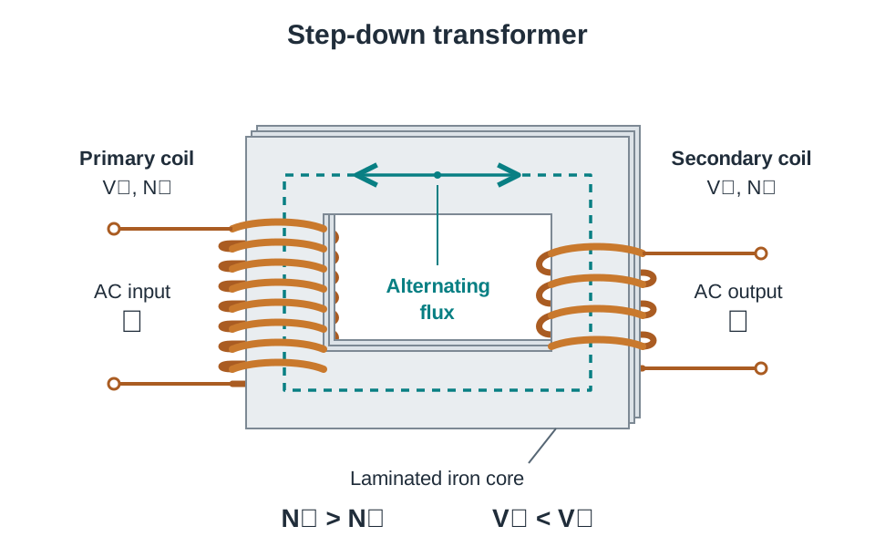
Essential Exam Diagram: The Transformer
Be prepared to sketch the basic transformer from memory: draw the rectangular laminated core, the primary coil on the input limb (), and the secondary coil on the output limb (), labelling the magnetic flux path inside the core.
Power Rectification, Smoothing, and Workshop Electrical Safety
Certain processes, such as Metal Inert Gas (MIG) welding, require DC because the zero-crossing points of AC cause arc instability and excessive spatter. A DC power supply converts mains AC into steady DC through three stages:
- Voltage step-down: a step-down transformer reduces 230 V AC to an operational level (typically 18 V to 36 V) and steps up available current. It also means there is no direct electrical connection between the welding circuit and the mains supply, so a fault in the welding leads cannot put mains voltage on the workpiece.
- Full-wave rectification: the low-voltage AC passes into a bridge rectifier made of four semiconductor diodes arranged in a diamond network. Diodes allow current to flow in one direction only. During both halves of the AC cycle, the diodes direct current through the output in the same direction, turning AC into pulsating DC.
- Capacitive smoothing: pulsating DC drops to zero twice per cycle. A reservoir capacitor connected in parallel across the output stores charge as the voltage wave climbs to its peak and discharges into the load as the voltage falls, turning pulsating DC into smooth DC.
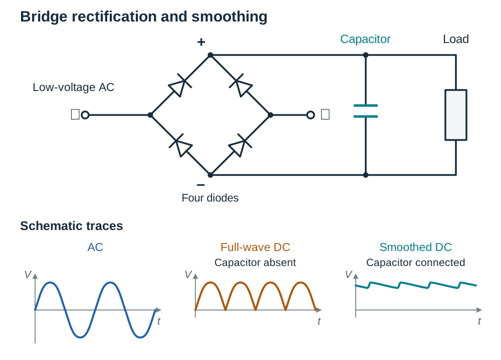
Essential Exam Diagram: Power Supply Stages and Waveforms
Practise sketching the three-block chain: AC input (sine wave) Step-down transformer Bridge rectifier (diamond of 4 diodes; pulsating humps) Smoothing capacitor (nearly flat DC line) DC load.
Single-Phase versus Three-Phase Systems
- Single-phase (230 V): delivered via Live (brown), Neutral (blue), and Earth (green/yellow). Used for hand tools, bench drills, and lighting.
- Three-phase (400 V): delivered via three separate live phase conductors separated by 120°, plus neutral and earth. The potential difference between any two phases is 400 V AC. It provides smooth, constant torque to large electric motors on centre lathes, milling machines, and compressors without requiring starting capacitors.
Electrical Protection and Life Safety
- Earthing: the conductive metal casing of a machine is connected to ground via a low-resistance earth wire. If a loose live wire touches the casing, a massive fault current flows directly to earth. This surge immediately blows the fuse or trips the circuit breaker, cutting power before someone touching the frame receives a shock.
- Fuses and miniature circuit breakers (MCBs): a fuse contains a thin wire that melts when current exceeds its rating. An MCB uses thermal and magnetic trips to open an internal switch during overloads or short circuits. Both devices protect cables and motors from overheating and fire; they do not protect people from shock.
- Residual Current Device (RCD): compares the current flowing out on the live wire with the current returning on the neutral wire. In a healthy circuit, these are equal. If someone touches a live component, current leaks through their body to earth. The RCD detects this small difference in current — as little as 30 mA — and disconnects the supply in a few tens of milliseconds, preventing fatal electric shock.
Electronic Components, Sensing Circuits, and Digital Logic
Automated circuits rely on discrete components to process sensor signals and switch machinery:
- Resistors: restrict current flow and drop voltage according to Ohm's Law (). In series, resistances add (). In parallel, the combined resistance is lower: , or .
- Capacitors: store electrostatic charge on conductive plates separated by an insulator (dielectric). They smooth rectified DC, filter electrical noise, and provide timing delays.
- Diodes and LEDs: diodes allow one-way current flow. A flyback diode is wired in reverse parallel across an inductive coil (such as a relay or solenoid) to safely conduct and dissipate the high reverse-voltage spike created when the coil is de-energised, protecting driving transistors. Light-emitting diodes (LEDs) emit light when forward-biased and need a series resistor to prevent burning out.
- Transistors: three-terminal devices with Base, Collector, and Emitter. When the base-emitter voltage reaches about 0.7 V, the transistor starts to conduct. As the base current increases further, the transistor saturates — it is then fully on and acts as a closed switch with no moving parts.
- Relays: electromechanical switches where a low-voltage coil (e.g. 5 V logic) pulls an armature to open or close isolated 230 V AC contacts, keeping low-voltage controls completely separate from mains power.
Potential Dividers and Transistor Switching
Two resistors in series split the supply voltage according to their resistance ratio:
In a light-operated switch, a light-dependent resistor (LDR) and a variable resistor form a potential divider. In darkness, an LDR has high resistance (megohms), which falls to a few hundred ohms in bright light. In a temperature-operated switch, a negative temperature coefficient (NTC) thermistor is used, whose resistance drops as temperature rises. When the junction voltage reaches 0.7 V, base current flows, switching on the transistor and energising a relay coil.
Logic Gates and Truth Tables
Digital controllers use transistors as binary switches (logic 1 = high/on; logic 0 = low/off):
- AND gate: output is 1 only when all inputs are 1. Used in two-hand safety presses.
- OR gate: output is 1 when at least one input is 1. Used where multiple guards or buttons can trigger an action.
- NOT gate (inverter): output is the inverse of the single input (0 gives 1, 1 gives 0).
- NAND gate: output is 0 only when all inputs are 1 (AND inverted).
- NOR gate: output is 1 only when all inputs are 0 (OR inverted).
Input Sensors in Automation
| Sensor Type | Operating Principle | Engineering Advantages | Practical Limitations |
|---|---|---|---|
| Mechanical limit switch | Moving machine part strikes a roller or plunger, operating physical contacts. | Handles high currents directly; immune to electrical noise; fail-safe when wired NC. | Moving parts wear; contact bounce; requires physical contact with workpiece. |
| Inductive proximity sensor | High-frequency magnetic field detects dampening caused by eddy currents in nearby metal. | Non-contact; immune to non-metallic workshop dust, cutting fluids, and oil. | Detects conductive metals only; short sensing range (typically 1 mm to 15 mm). |
| Photoelectric sensor | Projects an infrared/visible light beam to a phototransistor (through-beam, retroreflective). | Long sensing range (several metres); detects non-metallic parts and transparent items. | Optical lenses can be blinded by airborne dust, oil spray, or cutting mist. |
| Reed switch | Sealed ferromagnetic contacts in a glass capsule pulled closed by a magnet. | Hermetically sealed against explosive workshop fumes; simple two-wire connection. | Glass envelope is fragile; contacts can weld under excessive inrush currents. |
| Hall effect sensor | Semiconductor slab develops a voltage when a perpendicular magnetic field is applied. | Completely solid-state with long service life; high switching speed for shaft encoders. | Sensitive to extreme heat and electrostatic discharge; requires a DC power supply. |
Safety switches and emergency stops are always wired Normally Closed (NC). Current flows continuously through the closed circuit during normal operation. If a wire breaks or a stop button is struck, the circuit opens, immediately stopping the machine in a fail-safe condition.
Pneumatics and Fluid Power in Automation
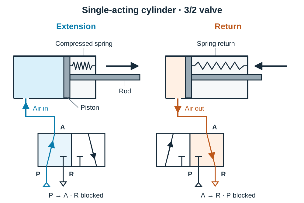
Pneumatics uses compressed air to produce clean, fast, and repeatable linear motion. Air is drawn in by a compressor, stored in an air receiver, and conditioned through a service unit (FRL unit: filter, regulator, and lubricator) to remove water and dirt, set the operating pressure (typically 6 bar), and add an oil mist to lubricate moving seals.
Actuators and Directional Control Valves
- Single-acting cylinder: has one air port and an internal return spring. Compressed air enters the rear port, forcing the piston rod out on the power stroke and compressing the spring. When the air supply exhausts, the spring pushes the piston back. Work is done in one direction only. It is controlled by a 3/2 valve (3 ports, 2 positions).
- Double-acting cylinder: has two air ports and no spring. Air supplied to the rear port extends the piston while the front port exhausts. Switching air to the front port retracts the piston while the rear exhausts. Work is done in both directions, delivering greater return force. It is controlled by a 5/2 valve (5 ports, 2 positions).
- Solenoid valve: an electrical coil that shifts a pneumatic valve spool when energised. This allows a low-voltage electronic controller or robot to switch high-force pneumatic actuators directly.
Cylinder Force Calculation
The theoretical force exerted on the out stroke is calculated from pressure and piston area:
Where is force in newtons (N), is air pressure in pascals (), and is the cross-sectional area of the cylinder bore (, with diameter in metres).
Industrial Robotics and CNC Part Programming
An industrial robot is a reprogrammable, multi-functional manipulator designed to move materials, parts, tools, or specialised devices through variable programmed motions.
Robot Configurations
- Articulated (jointed-arm): rotary joints mimicking a human arm. Offers a large, flexible work envelope; widely used for spot welding, spray painting, and assembly.
- Cartesian (gantry): three linear sliding axes () mounted at right angles. Highly rigid and accurate over a rectangular envelope; used for pick-and-place, machine loading, and 3D printing.
- SCARA: two parallel rotary joints providing fast horizontal reach plus a vertical axis. Rigid in the vertical plane; ideal for high-speed printed circuit board (PCB) assembly.
- Cylindrical/polar: rotating base with a combination of linear and angular reach; used for machine tending and transfer operations.
Control Parameters and Safety
- Degrees of freedom: the number of independent axes along which the arm can move (typically 6 axes on an articulated robot: 3 arm joints for positioning, and 3 wrist joints for pitch, roll, and yaw).
- Work envelope: the complete 3D space reached by the robot's end effector (the tooling or gripper fitted to the arm flange).
- Payload: the maximum mass the robot can carry, including the end effector and the workpiece, at full reach without loss of accuracy. Manufacturers quote it at rated speed; carrying more than the payload causes positional error, joint overload, and reduced service life.
- Repeatability: how consistently the robot returns to the exact same position over thousands of cycles (typically ). Spot welding requires high repeatability.
- Safeguarding: the work envelope must be enclosed by physical interlocked fences, light curtains, or pressure mats wired through Normally Closed (NC) contacts to cut drive power instantly if someone enters the danger zone.
Actuator Control: Steppers, Servos, and Inspection
- Stepper motor: rotates in discrete angular steps (e.g. 1.8° per pulse). The controller keeps track of position by counting pulses (open-loop control). However, if an external torque exceeds motor capability, the motor slips or loses steps without the controller detecting the error.
- Servomotors: combine an electric motor with an optical shaft encoder for closed-loop control. The controller compares actual position against commanded position and adjusts power continuously, preventing lost steps under varying loads.
- Feedback and inspection: machine vision uses digital cameras and software to inspect parts, verify orientation, and guide robot tools along seam lines.
Programming and CNC Lathe G-Code
Robots are programmed either online using a teach pendant (hand-held unit driving the arm to record points, taking the cell out of production) or offline via CAD/CAM software (simulating toolpaths on a computer without halting production).
In CNC machining, parts are programmed relative to a workpiece datum (zero point):
- Absolute positioning (G90): all coordinates are referenced from the fixed workpiece zero.
- Incremental positioning (G91): each coordinate is measured relative to the current tool position.
Standard codes include:
- G00: rapid traverse (non-cutting positioning).
- G01: linear feed cutting at a programmed feed rate.
- G02 / G03: circular interpolation clockwise / anticlockwise.
- M03 / M05: spindle start clockwise / spindle stop.
- M06: automatic tool change.
- M08 / M09: coolant on / coolant off.
- M30: end of program and rewind.
The CAD/CAM Workstation
A CAD/CAM workstation relies on specific hardware components:
- CPU (Central Processing Unit): executes design and toolpath calculations.
- RAM: fast, volatile working memory that holds active 3D models and programs.
- ROM: permanent, non-volatile memory holding basic startup firmware.
- Storage: solid-state drives for permanent file and drawing storage.
- Peripherals: input devices (mouse, 3D spaceball, digitiser) and output devices (high-resolution monitor, plotter, CNC machine interface).
Prime Movers, Power Transmission, and Mechanisms
A prime mover converts a natural source of energy into mechanical work, typically delivered as a rotating shaft. Power transmission systems transfer this rotary power from the prime mover to the working load, altering speed, torque, or direction.
The Four-Stroke Petrol Engine
The piston completes four strokes (two crankshaft revolutions) per operating cycle:
- Induction: the inlet valve opens, the piston descends, and the resulting low pressure draws in a fuel–air mixture.
- Compression: both valves close, and the rising piston compresses the mixture (ratio typically 9:1), raising its temperature and readiness to burn.
- Power (expansion): a spark plug ignites the compressed mixture near top dead centre. Rapidly expanding hot gases force the piston down. This is the only stroke that delivers useful mechanical work to the crankshaft.
- Exhaust: the exhaust valve opens, and the rising piston expels the burnt gases into the exhaust manifold.
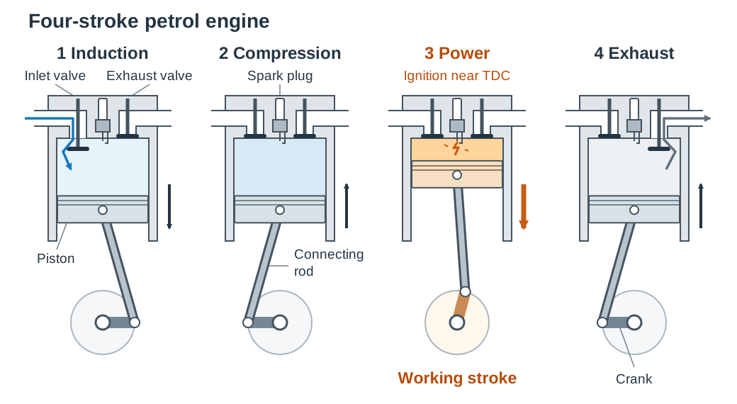
A heavy flywheel stores kinetic energy during the power stroke to maintain smooth rotation through the other three non-working strokes. In a diesel engine, air alone is compressed to a high ratio (roughly 18:1), heating the air so intensely that diesel fuel ignites spontaneously when injected into the cylinder without needing a spark plug (compression ignition).
Mechanical Power Transmission
- Spur gears: positive drive with zero slip, compact, suitable for heavy loads, but require lubrication and can be noisy.
- Toothed (timing) belts: positive drive without slip, require no lubrication, and run quietly; limited torque capacity.
- V-belts: grip by friction wedge action, run quietly, and slip under excessive overload (acting as mechanical overload protection), but cannot provide synchronised timing.
- Roller chains: positive drive across larger shaft centre distances; withstand high torque but require lubrication and tensioning.
The gear ratio (velocity ratio) is determined by tooth counts:
Assuming negligible friction losses, torque changes in inverse proportion to rotational speed: a reduction gear train lowers output shaft speed while multiplying output torque.
Sustainable Energy Systems: Photovoltaics, Hybrids, and Fuel Cells
Energy engineering focuses on high-efficiency conversion and low environmental impact across renewable and automotive systems.
Photovoltaic (PV) Cells
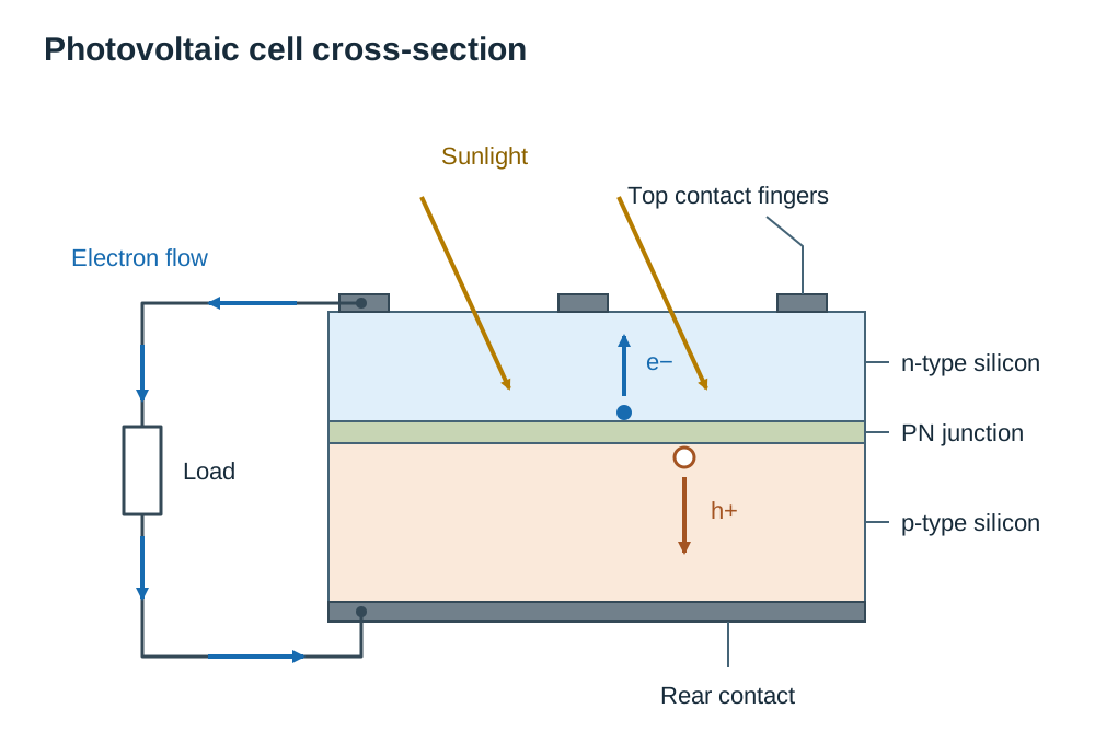
Photovoltaic cells convert sunlight directly into DC electricity through the photovoltaic effect. A PV cell consists of two thin layers of doped silicon forming a PN junction. Light energy striking the silicon knocks electrons free from their atoms, leaving behind positive holes. The electric field across the internal PN junction sweeps free electrons toward the n-type layer and holes toward the p-type layer. An external circuit connected between the top metal contact fingers and the rear contact plate allows electrons to flow as direct current.
A domestic PV installation consists of a rooftop array DC isolator switch electronic inverter (converting DC to 230 V, 50 Hz AC) consumer unit and grid-export meter. Electrical output depends on solar irradiance (W/m²), roof orientation and tilt (south-facing at 30° to 40° in Ireland), shading, and panel temperature (voltage drops as panels get hot, requiring a rear ventilation gap). Panels in series add voltages; parallel strings add currents. Solar PV has no moving parts, no operating emissions, and low maintenance, but suffers from high upfront cost, intermittent generation, and zero output at night.
Hybrid Vehicle Powertrains
Hybrid electric vehicles combine an internal combustion engine with an electric motor-generator and a high-voltage traction battery:
- Regenerative braking: when decelerating, the vehicle's kinetic energy back-drives the electric motor as a generator. This produces electrical resistance that slows the car while generating current to recharge the traction battery, capturing energy that friction brake pads waste as heat.
- Stop-start driving: the electric motor launches the vehicle with instant torque from rest, allowing the petrol engine to remain off during traffic stops and low-speed crawling to cut urban emissions and fuel consumption.
- Configurations: in a series hybrid, only the electric motor drives the wheels; the engine merely drives a generator. In a parallel hybrid, both engine and motor are mechanically coupled to the transmission and can power the wheels together or separately. In a series-parallel (power-split) hybrid, a planetary gearset blends both modes automatically. Plug-in hybrids (PHEVs) feature a larger battery charged from mains electricity for extended zero-emission electric range.
- Limitations: higher purchase cost, complex maintenance, extra mass from the battery pack, limited efficiency gains on continuous high-speed motorway driving, and hazardous high-voltage cabling (coloured orange) requiring specialised safety procedures.
Hydrogen Fuel Cells
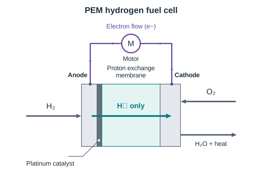
A Proton Exchange Membrane (PEM) fuel cell converts the chemical energy of hydrogen fuel directly into electricity without combustion:
- Pressurised hydrogen () enters the anode, where a platinum catalyst splits each molecule into protons (hydrogen ions, ) and electrons ().
- The central proton exchange membrane allows positively charged protons to pass through but blocks electrons.
- The blocked electrons travel through an external electrical circuit, generating direct electric current (DC) that powers vehicle motors.
- Oxygen () from ambient air enters the cathode.
- Arriving electrons, migrated protons, and oxygen combine at the cathode to form pure water () and heat as the only by-products.
Key terms
- Step-Down Transformer
- An electrical device that uses electromagnetic induction to decrease AC voltage while proportionally increasing current, having more turns on its primary coil than its secondary coil.
- Bridge Rectifier
- An arrangement of four semiconductor diodes in a diamond network that converts alternating current into full-wave pulsating direct current.
- Residual Current Device (RCD)
- A life-safety device that compares live and neutral currents, tripping the supply in milliseconds if an earth-leakage imbalance of 30 mA occurs.
- Flyback Diode
- A diode connected in reverse parallel across an inductive coil to dissipate high-voltage back-EMF spikes when the circuit is opened, protecting driving transistors.
- Potential Divider
- A circuit of two or more resistors in series that divides an input voltage in proportion to their resistances, often used to create sensor-triggered voltage signals.
- Degrees of Freedom
- The number of independent axes or directions along which a robotic manipulator or mechanism can move or rotate.
- Work Envelope
- The total three-dimensional volume of space that a robot end effector can reach during operation.
- End Effector
- The tooling, gripper, or welding gun mounted on the wrist flange of an industrial robot arm to carry out work.
- Stepper Motor
- An electric motor that rotates in discrete, fixed angular steps per digital input pulse, providing precise open-loop position control.
- Normally Closed (NC)
- A switch configuration where contacts remain closed during normal operation so that a severed wire or activated switch breaks the circuit, ensuring fail-safe shutdown.
- Regenerative Braking
- An energy-recovery system that uses the vehicle drive motor as an electric generator during deceleration to slow the vehicle and recharge the battery.
- Proton Exchange Membrane
- The solid electrolyte in a PEM fuel cell that allows hydrogen protons to pass to the cathode while forcing electrons through an external circuit.
Check yourself
A transformer has 2,300 primary turns and 200 secondary turns on a 230 V AC supply. What is the secondary voltage?
Vs = 230 × (200 / 2300) = 20 V AC.
What is the function of a reservoir capacitor connected in parallel across the output of a bridge rectifier?
It smooths out the pulsating DC voltage by storing electrical charge at voltage peaks and discharging into the load during voltage troughs.
Why are workshop emergency stop switches wired to Normally Closed (NC) contacts rather than Normally Open (NO) contacts?
An NC circuit ensures that if a wire breaks, disconnects, or power is lost, the circuit opens instantly, stopping the machine in a fail-safe condition.
What is the difference between open-loop and closed-loop control in robotic motors?
Open-loop control (stepper motors) commands position by counting pulses without feedback; closed-loop control (servomotors) uses a rotary encoder to verify and correct position continuously.
A stepper motor has a step angle of 7.5°. How many digital pulses are required to rotate the motor shaft through 90°?
90 / 7.5 = 12 pulses.
What role does an inverter play in a domestic solar photovoltaic system?
It converts the variable direct current (DC) generated by the solar panels into synchronized 230 V, 50 Hz alternating current (AC) for household appliances and the grid.
How does regenerative braking in a hybrid car recover energy during deceleration?
The electric drive motor acts as an electrical generator driven by the vehicle's momentum, slowing the car and converting kinetic energy into electrical energy to recharge the battery.
What are the only two by-products produced during the normal operation of a hydrogen PEM fuel cell?
Pure water (H₂O) and heat.