

The Periodic Table and Engineering Alloys
The periodic table arranges all known chemical elements in order of atomic number, which is the number of protons in an atom's nucleus. Horizontal rows are called periods, while vertical columns are called groups. Elements located in the same group share similar chemical characteristics because they possess the same number of outer-shell valence electrons.
Metals versus Non-Metals
Metals sit on the left and centre of the table, while non-metals sit on the right. A stepped line of metalloids, such as silicon, separates the two groups. Metals are shiny when cut, conduct heat and electricity well, have high melting points and densities, and are malleable and ductile. Non-metals are dull, brittle in solid form, have low melting points, and act as electrical insulators (with carbon in the form of graphite being a notable exception).
Key chemical symbols tested in engineering include iron (Fe), copper (Cu), aluminium (Al), zinc (Zn), lead (Pb), tin (Sn), nickel (Ni), chromium (Cr), silver (Ag), gold (Au), and carbon (C).
Why Alloys Matter
An alloy is a mixture of a metal with one or more other elements. Pure metals are often too soft, weak, or prone to chemical attack for heavy structural work. Mixing elements alters the crystal lattice and improves properties such as tensile strength, hardness, wear resistance, and machinability.
- Mild steel: iron with up to 0.3% carbon. It is much stronger and tougher than pure iron.
- Brass: an alloy of copper and zinc. It is harder than pure copper, resists corrosion, and is easy to machine.
- Bronze: an alloy of copper and tin. It provides high wear resistance and low friction, making it ideal for sleeve bearings.
- Stainless steel: iron alloyed with chromium and nickel. The chromium creates an invisible self-healing oxide film that resists rusting.
Atomic Structure and Metallic Bonding
Every solid material is held together by interatomic forces. In other materials, atoms bond either by a metal atom giving electrons to a non-metal atom (ionic bonds, as in sodium chloride) or by non-metal atoms sharing pairs of electrons (covalent bonds). Engineering metals, by contrast, bond through a collective electronic structure known as the metallic bond.
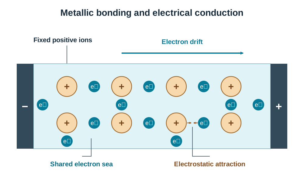
In metals, outer-shell valence electrons are held loosely by their parent nuclei. These valence electrons detach and form a freely circulating sea of delocalised electrons, leaving behind a rigid geometric framework of fixed positive metal ions (cations). Strong electrostatic attraction between the positive ions and the negative electron cloud binds the lattice together.
This bonding model explains two fundamental mechanical and physical properties of metals:
- Electrical and thermal conductivity: When a voltage is applied across a metal, the free electrons drift towards the positive terminal to create an electric current. The same free electrons also pick up heat energy at the hot end and carry it quickly through the metal, which is why metals are good conductors of heat.
- Plastic deformation: Metallic bonds are non-directional. When an applied shear load forces entire planes of atoms to slide past one another, the bonds break and immediately re-form with new neighbouring ions. The metal changes shape permanently without shattering.
Crystal Unit Cells: BCC, FCC, and CPH
When liquid metal solidifies, its atoms settle into ordered three-dimensional geometric frameworks called crystal lattices. The smallest repeating group of atoms that displays the full geometric symmetry of the lattice is the unit cell.
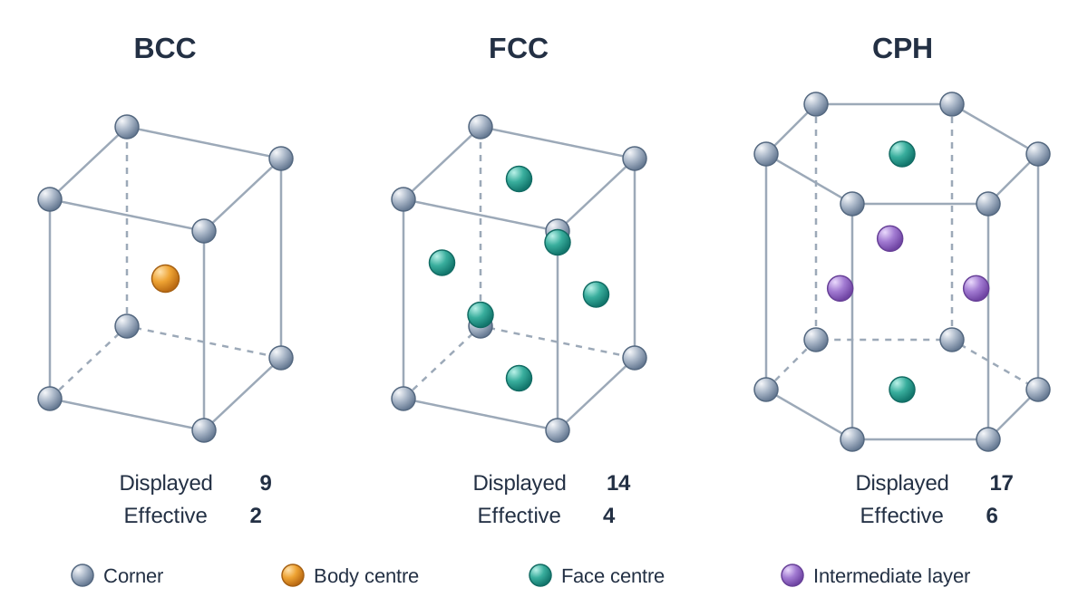
In school examination sketches, unit cells are represented by their visual atom models. A Body-Centred Cubic (BCC) cell is drawn with 9 atoms: 8 at the corners of a cube and 1 in the centre. A Face-Centred Cubic (FCC) cell is drawn with 14 atoms: 8 at the corners and 1 centred on each of the 6 faces. A Close-Packed Hexagonal (CPH) cell is drawn with 17 atoms: 12 corner atoms on two hexagonal end faces, 2 face-centre atoms, and 3 spacer atoms in a central layer.
If an examination question asks for the effective atom count belonging entirely to one cell (sharing corner atoms among adjacent cells), BCC contains 2 atoms, FCC contains 4 atoms, and CPH contains 6 atoms.
| Crystal Structure | Visual Sketch Count | Packing Efficiency | Typical Engineering Metals | Mechanical Character |
|---|---|---|---|---|
| BCC | 9 atoms | Looser packing (~68%) | Alpha-iron (ferrite), chromium, tungsten | Strong, hard, less ductile |
| FCC | 14 atoms | Close-packed (~74%) | Gamma-iron (austenite), copper, aluminium | Soft, highly ductile, easy to cold work |
| CPH | 17 atoms | Close-packed (~74%) | Zinc, magnesium, titanium, cadmium | Prone to rapid work-hardening, limited cold forming |
Why FCC is More Ductile Than BCC
Permanent bending and stretching occur through slip, which is the sliding of atomic layers over one another under shear stress. Slip occurs most easily along planes where atoms touch directly (close-packed planes) and in directions of closest atomic spacing.
An FCC lattice has 4 sets of close-packed planes with 3 close-packed directions in each, giving 12 active slip systems. Because atoms are closely packed along these planes, atomic planes glide over one another under moderate stresses. BCC has no truly close-packed planes. It requires significantly higher shear forces to initiate slip, making BCC metals like alpha-ferrite stronger and harder, but less ductile.
Allotropy and the Phase Changes of Iron
Allotropy is the ability of a pure element to exist in two or more different crystalline forms in the solid state depending on temperature and pressure.
Pure iron provides the classic engineering example of allotropy. Its structural changes form the foundation for the heat treatment and hardening of steels:
- Alpha-iron (Ferrite): Exists from room temperature up to 912°C. Iron takes a BCC crystal structure. In this phase, iron is magnetic up to 768°C (its Curie point). It is relatively strong, hard, and less ductile. Ferrite has small spaces between its iron atoms, allowing it to dissolve only a tiny amount of carbon (a maximum of 0.02% by weight at 723°C).
- Gamma-iron (Austenite): Exists between 912°C and 1394°C. The atoms rearrange into an FCC structure. Austenite is non-magnetic, soft, and ductile. Although FCC has a higher overall packing density than BCC, its empty space is grouped into fewer, larger gaps. This allows austenite to dissolve up to 2.14% carbon by weight.
- Delta-iron: At 1394°C the atoms change back into a BCC structure. Delta-iron is stable from 1394°C until pure iron melts at 1538°C.
Because austenite holds more than one hundred times as much carbon as ferrite, heating steel into the austenite range and quenching it rapidly in cold water traps the dissolved carbon before it can separate out. This lattice distortion creates martensite, the hard structure in quenched steel.
Solidification, Grain Size, and Ingot Structure
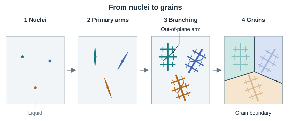
Solidification transforms molten metal into a solid crystalline mass through four clear stages:
- Nucleation: As molten metal cools to its freezing point, small groups of atoms slow down and bond into tiny solid crystal centres called nuclei.
- Primary arm growth: Heat leaves the cooling metal, and crystals shoot out rapidly along preferred directions, forming central spines or trunks.
- Secondary and tertiary branching: Secondary branches grow out at right angles to the central trunk, and tertiary arms branch off those, forming a three-dimensional tree-like crystal called a dendrite.
- Grain boundary formation: The remaining liquid freezes between the branches, thickening the dendrite arms until adjacent dendrites meet. The boundary surfaces where misaligned dendrites collide form permanent grain boundaries. Each solid dendrite becomes an individual grain.
Factors Controlling Grain Size
Fine-grained metals have more grain boundaries per unit volume. Grain boundaries block the movement of dislocations, making fine-grained metals stronger, harder, and tougher than coarse-grained metals of identical composition.
- Cooling rate: Rapid cooling (such as in a metal chill mould or die casting) forms many nuclei at once, producing fine grains. Slow cooling (such as in an insulated sand mould) creates fewer nuclei, leading to large, coarse grains.
- Nucleating agents: Adding small quantities of inoculants (such as titanium or boron in molten aluminium) provides extra solid particles for crystals to freeze around, refining grain size.
- Mechanical working: Hot rolling or forging crushes coarse cast grains, which then recrystallise into smaller grains.
- Heat treatment: Normalising refines grain size by heating steel above its critical temperature and cooling it in still air.
Structure of an Ingot or Casting
When molten metal is poured into a cold ingot mould, three distinct cooling zones develop across its cross-section:
- Chill zone: A thin outer skin of small, randomly oriented (equiaxed) grains formed immediately against the cold mould wall due to rapid heat loss.
- Columnar zone: Long, slender grains that grow inward from the chill zone, growing in the direction opposite to heat flow.
- Equiaxed zone: Large, rounded grains at the centre where cooling is slower and equal in all directions.
- Shrinkage cavity (pipe): A hollow funnel formed at the top centre of an ingot because molten metal contracts as it cools, and the top centre freezes last.
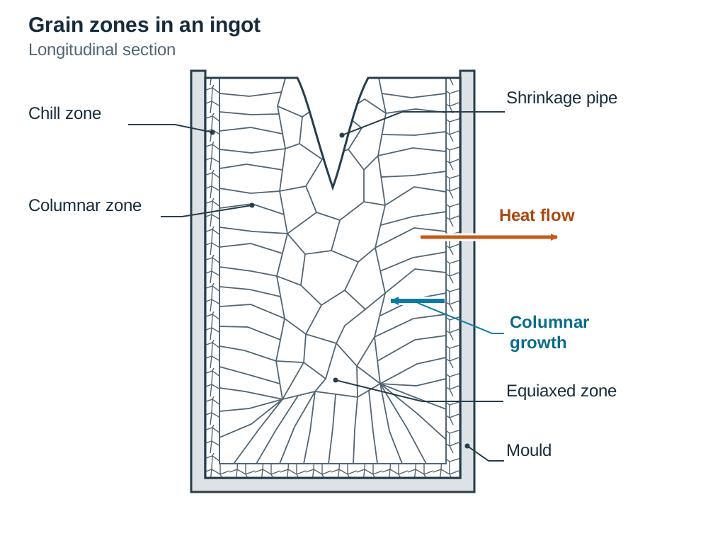
To carry out a macroscopic examination, technicians cut a cross-section of the ingot, grind and polish the surface smooth, and etch it with a mild acid. The acid attacks grain boundaries and crystal faces at different rates, revealing the three zones, pipe defects, and forging flow lines clearly to the naked eye.
Crystal Defects and How Alloys Form
Real engineering metals are never perfect crystals. Microscopic imperfections govern whether a metal is soft and malleable or hard and strong.
Point Defects (Zero-Dimensional)
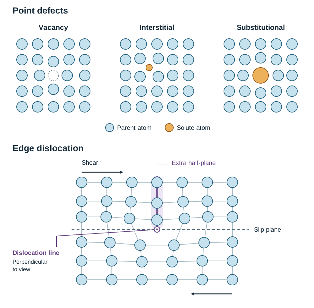
- Vacancy: An atom is missing from its normal position in the lattice. Neighbouring atoms pull inward, straining the surrounding structure.
- Interstitial defect: A small foreign atom (such as carbon in iron) wedges into the empty space between parent metal atoms, pushing the surrounding atoms outward.
- Substitutional defect: A foreign atom takes the place of a parent atom on a regular lattice site. A larger solute atom creates compressive lattice stress, while a smaller one creates tensile stress.
Point defects increase strength and hardness because the distorted lattice blocks the passage of dislocations. However, this distortion reduces ductility and lowers electrical conductivity, because the irregular lattice scatters flowing electrons.
Line Defects: Edge Dislocations (One-Dimensional)
The most common line defect is an edge dislocation, which consists of an extra half-plane of atoms squeezed partway into the crystal lattice. Dislocations allow metals to deform plastically without snapping. Instead of breaking every atomic bond across an entire plane simultaneously, bonds break and re-form one row at a time. This operates like pushing a small ripple across a carpet, requiring far less force than sliding the entire carpet at once.
Under repeated (cyclic) loading, cracks can start and spread from these defects, leading to fatigue failure even when the applied load is well below the material's normal tensile strength.
Ways Metals Combine to Form Alloys
- Substitutional solid solution: Solute atoms replace solvent atoms in the parent lattice, as seen in zinc dissolving into copper to make alpha brass.
- Interstitial solid solution: Small solute atoms fit into the voids between parent atoms, such as carbon dissolving into iron.
- Eutectic: An alloy liquid of one exact composition changes directly into an intimate mixture of two separate solids at one fixed temperature, which is the lowest melting point in that alloy system (for example, 62% tin / 38% lead solder freezing at 183°C).
- Eutectoid: A single solid phase transforms into two different solid phases at a single fixed temperature (such as solid austenite transforming into pearlite at 723°C in steel).
When cold-worked metal is heated, distorted grains reform into new, strain-free crystals. This process is called recrystallisation, and it forms the basis of annealing.