

Materials testing evaluates how metals and alloys behave under mechanical loads and ensures finished components are sound and safe to use. In Leaving Certificate Higher Level Engineering, testing splits into destructive testing (tensile, hardness, impact, fatigue, bend, cupping, and creep) where a specimen is tested to permanent deformation or fracture, and non-destructive testing (NDT) using liquids, magnetism, sound, and radiation, which checks finished parts for defects without damaging them.
Strength of Materials: Tension, Compression, Shear, Bearing, Bending, and Torsion
Engineering structures must resist several distinct types of force:
- Tensile strength: the ability of a material to resist forces that pull or stretch it.
- Compressive strength: the ability of a material to resist axial forces that push or squeeze it. Materials like concrete and cast iron perform exceptionally well in compression but poorly in tension.
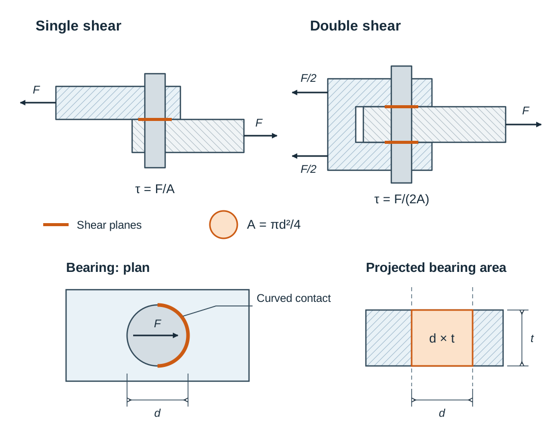
- Shear strength: the ability of a material to resist two equal forces acting parallel to each other in opposite directions, attempting to slide one plane of the material past another (for example, pins, rivets, and bolts).
Direct Stresses and Bearing Stress
Direct normal stress (tensile or compressive) is calculated as force divided by the load-bearing cross-sectional area:
where is stress in (or ), is force in , and is cross-sectional area in .
Shear stress () depends on how many planes resist the cutting force:
- Single shear: the pin or bolt is cut across one cross-section (), so .
- Double shear: the pin is supported inside a fork or clevis joint, so the load is shared across two cross-sectional planes (), halving the stress for a given applied load.
Bearing stress () occurs on the projected contact surface between a cylindrical fastener (such as a rivet or pin) and the hole wall of a plate:
where is fastener diameter and is plate thickness.
Bending and Torsion
- Bending: when a load acts across a beam, the beam curves. The face on the outside of the curve is stretched (tension) and the face on the inside is squeezed (compression). For example, a simply supported beam loaded from above has compression on top and tension underneath, while a cantilever has tension on top. The line between the two regions has zero stress and is called the neutral axis.
- Torsion: a twisting action (torque) applied to a shaft induces pure shear stress in the material. This shear stress is zero at the central axis and reaches a maximum at the outer circumference of the shaft.
Tensile Testing, Stress-Strain Graphs, and Ductility
A tensile test pulls a standard machined specimen along its longitudinal axis until fracture to measure strength, stiffness, and ductility. Raw load () and extension () data are converted into stress and strain:
where is the original cross-sectional area, is the original gauge length, and strain is a dimensionless ratio.
Key Graph Milestones for Low-Carbon Steel
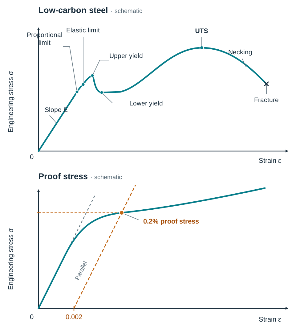
- Limit of proportionality: the point up to which Hooke's Law holds and stress is directly proportional to strain.
- Elastic limit: the maximum stress the metal withstands without suffering permanent deformation. Below this point, the specimen returns to its original dimensions.
- Yield point: the point where a sudden increase in plastic elongation occurs without an increase in applied load. Mild steel exhibits distinct upper and lower yield points.
- Ultimate Tensile Strength (UTS): the maximum load divided by the original cross-sectional area:
Necking starts at this point on a ductile specimen.
- Fracture point: the final stress level at which the test piece breaks apart.
Young's Modulus of Elasticity ()
The slope of the initial linear elastic line measures material stiffness:
For example, if a diameter steel bar () with a gauge length stretches under an load:
Proof Stress
Non-ferrous metals like copper and aluminium, as well as high-tensile steels, do not show a distinct yield point. Instead, engineers use proof stress (typically or ). A straight line is drawn parallel to the elastic slope, offset along the strain axis by or . The stress at the intersection with the curve is the proof stress.
Comparing Material Stress-Strain Curves
- Low-carbon steel: long elastic slope, sharp upper and lower yield points, large plastic region, clear necking.
- Copper and aluminium: short elastic slope, no yield point (proof stress required), extensive plastic curve showing high ductility.
- Cast iron: steep, nearly straight line up to sudden fracture with negligible plastic deformation (brittle).
Ductility Testing
- Tensile ductility: measured by Percentage Elongation, , and Percentage Reduction in Area, .
- Bend test: a flat bar or welded strip is bent around a mandrel of specified radius to a set angle (often ). The outer tension face is inspected for cracks.
- Erichsen cupping test: a hardened steel ball punch is driven into a clamped sheet-metal specimen until fracture begins. The depth of the impression in millimetres gives the Erichsen value; a higher depth indicates superior drawing quality.
Hardness, Impact, Fatigue, and Creep Testing
Hardness Testing
Hardness is the resistance of a material's surface to indentation, scratching, and abrasive wear. The hardness number is found from:
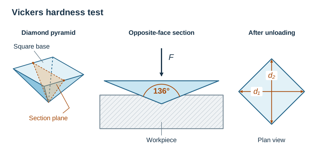
- Vickers test: uses a square-based diamond pyramid indenter with an included angle of between opposite faces. An operator measures both diagonals ( and ) optically to find the average diagonal . The Vickers hardness number is given by , where is in and is in . It suits all metals, from thin case-hardened layers to hard tool steels.
- Diagram requirements: pyramid indenter (), load arrow, workpiece, and square indentation with and .
- Brinell test: uses a hardened steel or tungsten carbide ball (typically diameter) pressed under high load. The indentation diameter is measured. It suits bulky structural castings and forgings.
Impact Testing
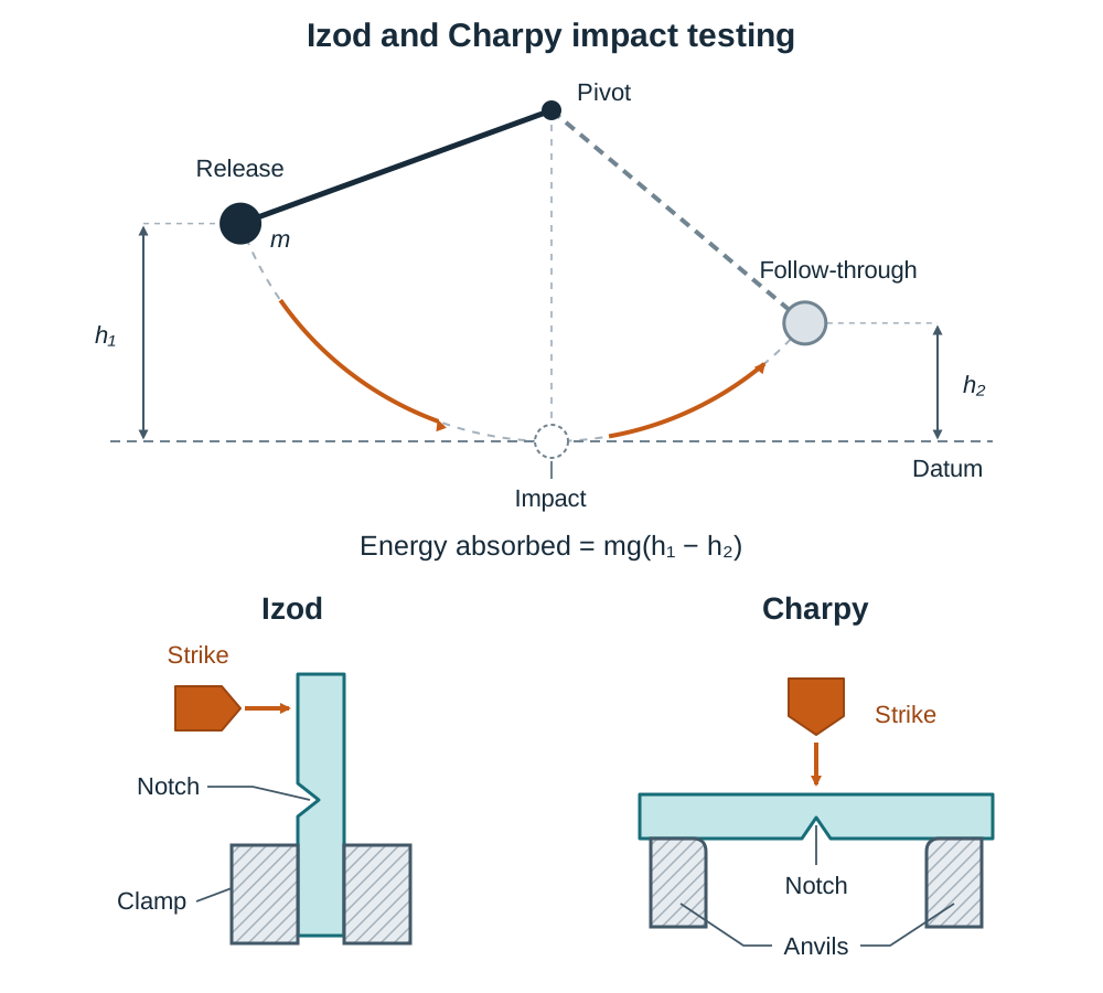
Impact tests measure toughness—the ability to absorb sudden dynamic shock energy without fracturing:
If a pendulum falls from and swings through to :
A standard notch (V or U shape) creates a concentrated stress point to produce a consistent fracture.
- Izod test: the specimen is clamped vertically like a cantilever. The notch faces the striking hammer, which hits the free upper tip.
- Charpy test: the specimen rests horizontally across two support anvils like a simple beam. The hammer strikes the back face directly opposite the central notch.
- Fractures: tough metals absorb high energy, deform plastically, and leave a dull, fibrous surface. Brittle metals absorb little energy, snap cleanly, and display bright, flat, crystalline facets.
Fatigue Testing
Metal fatigue is the failure of a metal under repeated (cyclic) loading at stresses well below its UTS. It starts as a microscopic crack at a surface stress raiser and grows cycle by cycle until the remaining sound metal snaps suddenly. Components like aircraft wings, axles, and engine crankshafts are vulnerable.
In the Wöhler test, a rotating specimen is loaded in bending and the number of cycles to failure () is plotted against applied stress () to create an - curve. Steels have a distinct endurance limit where the curve flattens; below this stress, the part will not fail regardless of the number of cycles. Non-ferrous alloys like aluminium have no endurance limit and continue downward, so designers specify fatigue strength at a designated cycle count (such as cycles).
Creep Testing
Creep is the slow, continuous plastic deformation of a metal subjected to a constant mechanical load over an extended period. It is accelerated at high operating temperatures, making it a critical design factor in jet engine turbine blades, steam pipes, and furnace parts. Lead and many plastics creep at room temperature.
A creep test maintains a specimen at constant temperature and load, recording extension over time:
- Primary creep: strain starts rapidly and then decelerates.
- Secondary creep: steady, constant strain rate. This steady rate is used in component design.
- Tertiary creep: strain accelerates, necking appears, and rupture occurs.
Surface and Near-Surface NDT: Penetrant, Magnetic Particle, and Eddy Current
Non-destructive testing (NDT) inspects engineering components for flaws without damaging them. It is used during manufacturing to prevent catastrophic in-service failure, verify quality without discarding components, and conduct routine maintenance inspections.
Visual Inspection
Visual checking is the primary step in quality control. Technicians check visible surfaces with the naked eye or low-power lenses for misalignments, weld undercut, missing fasteners, or severe surface cracking.
Liquid Penetrant Inspection (DPI / LPI)
Detects surface-breaking flaws in any non-porous solid (aluminium, stainless steel, ceramics, brass). It relies on capillary action through five steps:
- Clean: solvent-clean the surface to remove all grease, scale, and dirt.
- Apply penetrant: spray visible red dye or fluorescent penetrant over the surface. Allow a dwell time of 10 to 20 minutes so capillary action draws dye into minute cracks.
- Remove excess: lightly wipe off surface dye with a lint-free cloth dampened with cleaner, taking care not to wash dye out of the cracks.
- Apply developer: spray a light coat of chalky white developer. This blots trapped dye out by reverse capillary action.
- Inspect: examine under bright light (or UV blacklight for fluorescent dye). Red crack indications stand out against the white background.
Magnetic Particle Inspection (MPI)
Detects surface and shallow sub-surface defects in ferromagnetic materials (carbon steels, cast iron). It cannot be used on non-magnetic metals, such as aluminium, copper, or austenitic stainless steel.
- The part is magnetised using an electromagnetic yoke.
- A defect running across the flux path interrupts the magnetic lines, forcing them into the air and forming local north and south poles (magnetic flux leakage).
- Fine iron particles (dry powder or ink suspension) are applied and cluster directly at the leakage field, revealing the flaw.
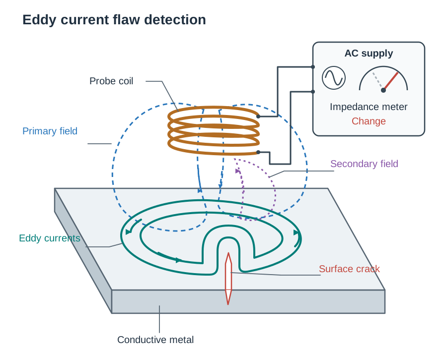
Eddy Current Testing
Inspects any electrically conductive metal for surface and near-surface flaws. It is especially useful for non-ferrous metals like aluminium, copper, and bronze, where magnetic particle testing cannot work.
- An alternating current (AC) is passed through a probe coil, creating an alternating primary magnetic field.
- When placed near a conductive metal, this field induces circulating loops of current called eddy currents.
- The eddy currents generate an opposing secondary magnetic field.
- A surface crack breaks the circulation path of the eddy currents, altering the secondary field and changing the electrical impedance of the coil.
- This impedance shift is detected on an instrument meter or oscilloscope screen.
- Diagram requirements: probe coil with AC supply, primary field lines, circulating eddy currents in metal, crack obstructing flow, and impedance meter.
Internal NDT: Ultrasonic and Radiography, plus Physical Properties
Ultrasonic Testing (UT)
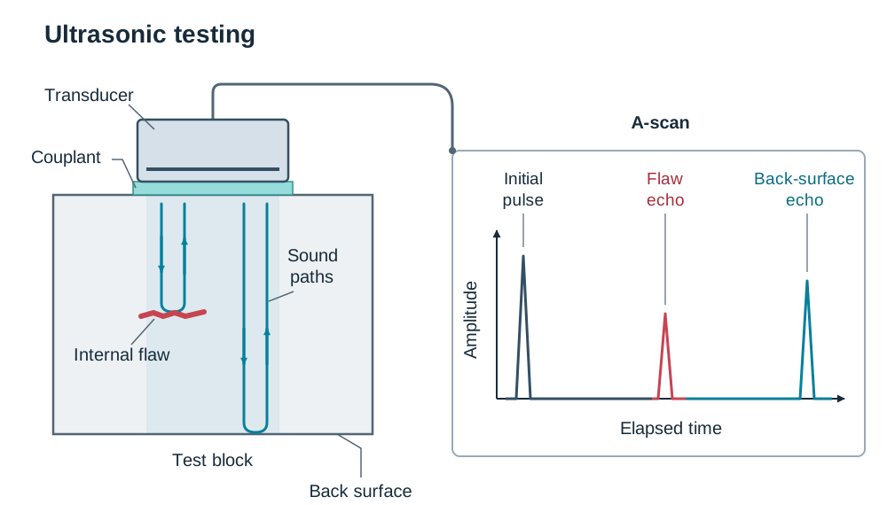
Detects deep internal defects (blowholes, slag, internal forging cracks) using high-frequency sound waves ():
- A piezoelectric transducer converts electrical signals into ultrasonic pulses.
- An acoustic couplant (gel or light oil) is applied between the probe and component to bridge the air gap, as air would reflect the sound waves before they enter the workpiece.
- Sound travels through the material and reflects back from internal interfaces and boundaries.
- An oscilloscope displays an A-scan signal showing:
- Initial pulse: where sound enters the front surface.
- Flaw echo: an early spike indicating an internal defect.
- Back-surface echo: reflection from the rear wall.
- The relative distance of the flaw echo between the front and back echoes gives the precise depth of the defect.
- Diagram requirements: probe, couplant layer, test block with internal flaw, and A-scan trace showing all three peaks.
Radiography Testing
Directs X-rays or gamma rays through the workpiece onto photographic film or digital sensors. Dense sound metal absorbs more radiation, leaving the film pale. Cracks, internal porosity, and inclusions absorb less radiation; more rays pass through, exposing the film to create dark marks. It provides a permanent photographic record but requires radiation safety enclosures and certified technicians.
Summary of Physical Property and Environmental Testing
- Thermal conductivity: the rate at which heat moves through a material (copper and aluminium have high conductivity, making them suitable for heat sinks and cooking utensils).
- Electrical conductivity: the capacity to pass an electric current (copper is the engineering standard for wiring).
- Thermal expansion: the change in dimensions caused by temperature variation (requires expansion gaps in bridges, railway tracks, and steam lines).
- Specific heat capacity: the energy needed to raise of a material by (measured in ).
- Environmental exposure tests: specimens are exposed to salt spray, moisture cabinets, or UV weathering cycles to assess corrosion resistance and coating durability before full-scale manufacturing.
Key terms
- Ultimate Tensile Strength (UTS)
- The maximum load supported by a tensile test specimen divided by its original cross-sectional area.
- Proof Stress
- The stress level that produces a specified permanent plastic strain (usually 0.1% or 0.2%) in materials lacking a distinct yield point.
- Young's Modulus of Elasticity
- The ratio of stress to strain within the proportional limit, measuring material stiffness in N/mm² or kN/mm².
- Toughness
- The ability of an engineering material to absorb dynamic shock energy and deform plastically before fracturing.
- Hardness
- The resistance of a material's surface to mechanical indentation, scratching, cutting, or abrasion.
- Endurance Limit
- The stress level on an S-N curve below which a ferrous metal survives an infinite number of cyclic stress reversals without fatigue failure.
- Creep
- The slow, continuous, time-dependent plastic deformation of a material subjected to constant mechanical stress, especially at elevated temperatures.
- Magnetic Flux Leakage
- The distortion and escape of magnetic field lines into the surrounding air at an internal or surface discontinuity in a magnetised ferromagnetic metal.
- Eddy Currents
- Circulating loops of electrical current induced inside an electrically conductive material by an alternating magnetic field.
- Acoustic Couplant
- A fluid medium such as gel or oil applied between an ultrasonic transducer and workpiece to eliminate air gaps and ensure sound transmission.
- Bearing Stress
- The compressive contact pressure exerted between the cylindrical surface of a pin or rivet and the internal curved wall of a fastener hole.
- Double Shear
- A mechanical joint configuration where an applied load is resisted across two distinct shear planes of a single fastener.
Check yourself
A cylindrical test piece of 12 mm diameter withstands a peak tensile load of 181 kN. What is its Ultimate Tensile Strength?
Area A = π * (6 mm)² ≈ 113.1 mm². UTS = 181,000 N / 113.1 mm² ≈ 1,600 N/mm² (or 1.6 kN/mm²).
Why is proof stress quoted instead of yield point for aluminium and copper?
Aluminium and copper lack a sharp yield point on their stress-strain graphs, so an offset line (usually 0.1% or 0.2% plastic strain) is drawn parallel to the elastic slope to determine an equivalent yield strength.
What is the primary difference in how Izod and Charpy specimens are mounted?
In an Izod test, the specimen is clamped vertically at one end like a cantilever. In a Charpy test, it rests horizontally across two supports like a simple beam.
How does an endurance limit differ between plain carbon steel and aluminium on an S-N curve?
Plain carbon steel exhibits a distinct endurance limit where the S-N curve levels off horizontally, below which fatigue failure will not occur. Aluminium does not have a true endurance limit; its curve continues downward, so a fatigue strength is quoted for a specific number of cycles.
What function does an acoustic couplant serve in ultrasonic testing?
Couplant bridges the probe and workpiece to exclude air, which would otherwise reflect the high-frequency sound pulses before they enter the metal.