

The Leaving Certificate Engineering Project asks you to design, build, test, and document a working model or prototype based on an annual brief set by the State Examinations Commission (SEC). Under the syllabus examined through June 2027, the course is split into two equal areas. Workshop Processes carries 300 marks in total: 150 marks for the practical examination carried out in your school workshop, and 150 marks for the assessment of workshop/laboratory work and projects. Materials and Technology accounts for the remaining 300 marks on the written examination, making the project coursework worth 25% of the overall 600 marks. A successful project works through the five basic functions named under Technology in the Workshop Processes section: research, development, design, production, and testing. These stages feed back into one another; testing often sends you back to modify a part or refine a mechanism.
Assessment Structure and the Engineering Design Process
A new Engineering specification was introduced to fifth year in September 2026. If you are sitting your examination in 2027, you are not on that new specification. Ignore mark weightings or time limits taken from the newer course—such as references to a 50% project weighting or a 45-hour limit—because they do not apply to you.
Examination Mark Breakdown
| Syllabus Section | Assessment Component | Higher Level Marks |
|---|---|---|
| Workshop Processes | Practical examination (held in your school workshop) | 150 |
| Workshop Processes | Coursework assessment (Project prototype and documentation) | 150 |
| Materials and Technology | Written examination | 300 |
| Total Marks | — | 600 |
Check the current SEC timetable for the exact date of your practical examination.
Under the Technology heading of the Workshop Processes syllabus, your work revolves around five sequential functions:
- Research: Exploring the mechanical principles behind the brief, investigating commercial mechanisms, and checking workshop materials.
- Development: Generating alternative concepts using sketches, making quick cardboard or wire mock-ups, and selecting your best solution.
- Design: Fixing materials, shapes, sizes, and manufacturing methods, then producing working drawings.
- Production: Planning an ordered sequence of operations and manufacturing components safely using lathe turning, milling, drilling, and benchwork.
- Testing: Operating your prototype systematically against your specification, recording test data, identifying mechanical defects, and making improvements.
The visiting examiner sees and operates your finished project in the workshop. High marks depend on reliable mechanical performance, crisp benchwork, and honest evaluation.
Brief Analysis, Specification, and Design Factors
The SEC issues an open design brief each year. Your first job is to analyse this brief and translate it into a clear set of design goals. Record your work as you go: brief analysis, sketches, drawings, parts lists, calculations, setup photos, and test results. Check the project brief issued by the SEC for your year for exactly what documentation must be submitted and by what date, as specific requirements are outlined there.
Factors to Consider When Designing
Under the Technology heading of the Materials and Technology syllabus, the design function is defined as the selection of materials, shapes, sizes, and processes. When designing, you must balance several core factors:
- Function: Does the mechanism perform the required tasks reliably and repeatably?
- Safety: Moving parts must be guarded, trapping points eliminated, sharp burrs removed, and electrical wiring insulated.
- Strength and Rigidity: Parts must carry loads without fracturing or bending out of alignment.
- Materials and Cost: Standard workshop stock should be used where possible to avoid unnecessary expense.
- Manufacture: The design must be realistic for the machinery and hand tools available in your workshop.
- Ergonomics: Switches, handles, and adjusters must be clearly visible and comfortable to operate.
- Maintenance: Parts that wear out or need battery changes must be accessible.
- Appearance and Finish: Surfaces must be prepared, deburred, and coated neatly.
- Environment: Consider battery life, power efficiency, and recyclability.
Writing a Measurable Specification
A strong specification sets clear, measurable numerical targets rather than vague wishes:
| Parameter | Weak Criterion | Strong (Measurable) Criterion |
|---|---|---|
| Physical Envelope | Must be fairly small. | Maximum dimensions must not exceed 250 mm × 160 mm × 130 mm. |
| Operating Speed | Moves at a nice speed. | The drive axle must rotate at 60 ± 5 rpm under full load. |
| Lifting Capacity | Lifts a weight. | Must raise a vertical load of 250 g through a height of 100 mm in under 4 seconds. |
| Power Supply | Runs on a battery. | Operates on a switched 9 V to 12 V DC supply with an accessible master switch. |
| Rigidity | Sturdy bracket. | The motor mounting plate must deflect less than 0.5 mm under stall torque. |
Recording the Design: Drawings, Parts Lists, and Concept Selection
Before cutting any metal or plastic, your project must exist clearly on paper so that someone else could build it.
Design Documentation Requirements
- Annotated freehand sketches: Pictorial (isometric) sketches showing how parts move, what materials are planned, and how joints work. Notes carry as many marks as the drawings.
- Dimensioned working drawings: Third-angle orthographic projections showing all views, dimensions in millimetres, hole centres, and sectional views through complex parts like bushed housings.
- Assembly drawing: An overall drawing showing how parts fit together, with balloon numbers linking to a parts list.
- Parts list: A complete record of raw stock and purchased components:
| Item | Part | Qty | Material | Size / Details |
|---|---|---|---|---|
| 1 | Base chassis | 1 | Mild steel | 200 × 120 × 3 mm |
| 2 | Motor bracket | 1 | Aluminium alloy | 60 × 50 × 2 mm |
| 3 | Drive axle | 1 | Bright mild steel | Ø8 × 140 mm |
| 4 | Bearing bush | 2 | Nylon / Brass | Ø12 OD × Ø8 ID × 10 mm |
| 5 | Drive motor | 1 | Purchased | 12 V DC geared motor (120 rpm) |
Concept Selection Using a Weighted Matrix
Develop at least three different solutions and evaluate them using a decision matrix. Score each concept from 1 to 5 against your criteria, multiply by the weighting, and add them up. For example, in Concept B below, non-slip drive scores 5 × 5 = 25.
| Criteria | Weight (1–5) | Concept A (Belt Drive) | Concept B (Compound Gears) | Concept C (Lead Screw) |
|---|---|---|---|---|
| Non-slip positive drive | 5 | 2 (10) | 5 (25) | 5 (25) |
| Ease of manufacture | 4 | 4 (16) | 3 (12) | 2 (8) |
| Compact size | 3 | 3 (9) | 4 (12) | 4 (12) |
| Availability of parts | 3 | 4 (12) | 5 (15) | 3 (9) |
| Total Score | — | 47 | 64 | 54 |
Examiners expect you to justify these numbers in your text. Here, Concept B was selected because gear teeth eliminate the slipping risks of a belt drive, while fitting into a much smaller chassis envelope than a lead screw.
Motion, Mechanisms, and Drive Sizing
First decide what motion the brief requires, then decide how to achieve the necessary speed and torque.
The Four Types of Motion
- Rotary: Turning continuously about an axis, like an axle or motor shaft.
- Linear: Moving in a straight line in one direction, like a conveyor belt.
- Reciprocating: Repetitive backwards-and-forwards movement along a straight line, like a slider or piston.
- Oscillating: Swinging back and forth around a fixed pivot point, like a pendulum or windscreen wiper.
Mechanisms That Convert Motion
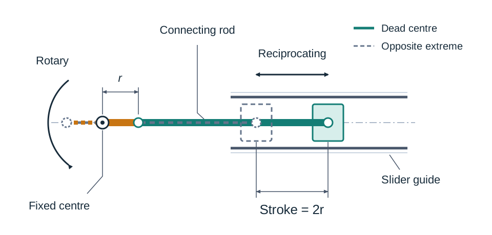
- Crank and slider: Converts rotary motion into reciprocating motion. The total stroke length equals twice the crank radius ().
- Cam and follower: Converts rotary motion into reciprocating or oscillating motion. The profile filed onto the cam governs follower movement.
- Rack and pinion: Converts rotary motion into linear motion without slip. Used for steering mechanisms and vertical drilling feeds.
- Screw and nut (lead screw): Converts rotary motion into slow, high-force linear motion. It is self-locking, meaning the load cannot push back.
- Lever / Linkage: Changes the direction of movement and provides mechanical advantage (). Note that torque is defined as , where is force in newtons and is perpendicular radius in metres.
Speed and Drive Calculations
Small direct-current (DC) motors turn fast (1,000–6,000 rpm) with low torque. Gear or belt reductions are essential.
- Velocity Ratio () for gears:
- Belt and Pulley Ratio:
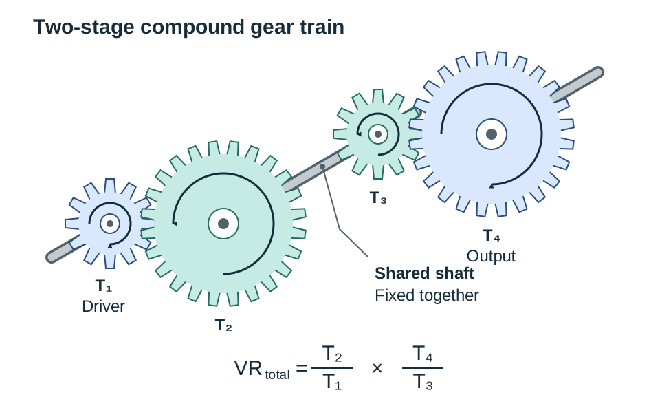
- Compound Gear Train: When single stages become too bulky, use a compound train on a shared intermediate shaft:
- Idler Gear: A gear placed between a driver and driven gear reverses the direction of rotation. It does not change the overall velocity ratio.
- Worm and wormwheel: Gives a very large speed reduction in a single compact stage (e.g. ) and cannot be back-driven, safely holding suspended loads without slipping.
Joining, Securing Shafts, and Material Selection
Deciding how to connect components and hold wheels to shafts is a key practical challenge examined on the Higher Level paper.
Securing Components to a Shaft
Wheels, gears, and pulleys must be locked so they cannot spin freely on a shaft or slip off sideways:
- Grub screw (socket-set screw): Threaded through the gear boss and tightened onto a small flat filed on the shaft. This flat stops burrs from swelling the shaft and preventing removal.
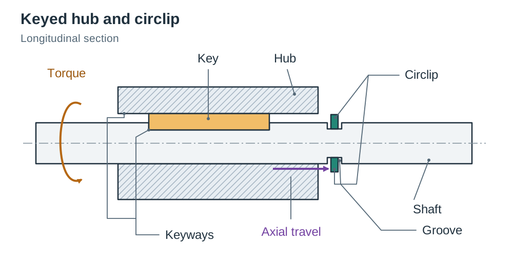
- Key and keyway: A rectangular steel key fits into a slot milled in the shaft and a matching internal keyway in the wheel hub. Best for high torque because the key carries load in shear.
- Taper pin or roll pin: Driven firmly through a cross-drilled hole through both hub and shaft. Provides a rigid, permanent drive.
- Circlip / E-clip: Snaps into an external groove turned on the shaft. It provides axial location only, preventing endwise sliding while letting another device carry the drive.
Choosing Joining Methods
Always classify connections as permanent or temporary:
- Mild steel base and brackets: Joined permanently using brazing or arc welding. Brazing requires less heat and minimizes distortion on thin sheet. Alternatively, use M4 bolts with locknuts for a dismantlable assembly.
- Removable service covers: Fastened using machine screws into tapped holes or nuts. Anything needing periodic inspection, battery replacement, or servicing must use a temporary joint.
- Acrylic panels: Joined permanently using solvent cement (Tensol). The solvent softens the acrylic faces, fusing them into a clear joint.
- Bearing bushes: Fitted into machined housings with a light interference press-fit or retaining compound, keeping the bore concentric without fasteners.
Material Selection: Strength versus Stiffness
Never call a material 'strong' without explaining the specific property:
- Mild steel (0.15–0.30% carbon): Medium tensile strength, very tough, ductile, and stiff. It will not crack under shock loads and welds easily. Excellent for baseplates, brackets, and axles.
- High carbon steel (silver steel): Contains roughly 1% carbon. Can be hardened and tempered. Used for pins, punches, scribers, and shafts requiring wear resistance.
- Aluminium alloy (e.g. 6082-T6): High strength-to-weight ratio, machines cleanly, and forms an innate protective oxide film. Ideal for moving robotic arms and lightweight chassis.
- Acrylic (PMMA): Rigid, clear thermoplastic. Cuts and polishes neatly, but is brittle and cracks around unbushed screw holes under vibration.
- Nylon / Polyacetal (Delrin): Self-lubricating, wear-resistant polymers. Perfect for sleeve bearings, guides, and intermediate reduction gears.
Workshop Processes, Surface Finishing, and Safety
Careful manufacturing sequence planning prevents spoiled parts and broken tooling.
Planning a Sequence of Operations (Flat Chassis Bracket)
Every step must have a sound practical reason:
- Cut sheet metal oversize using a bench shear to allow material for squaring up.
- File a true datum edge square and flat, because all subsequent marking out is measured from this edge.
- Coat with layout ink and mark out all bend lines and hole centres using a height gauge and scriber on a surface plate.
- Centre-punch hole centres so the drill point does not wander off mark.
- Drill all holes while the metal is still flat. Drilling after bending is inaccurate because vices cannot hold formed shapes securely.
- Deburr all drilled holes using a larger drill bit or countersink to ensure parts sit flush.
- Bend the bracket to the marked angle in a folding brake, or between hardwood or steel formers in the vice, so that the fold is straight and lands exactly on the marked bend line.
Machine Calculations: Spindle Speed
The spindle speed formula is:
One revolution moves the tool edge a distance equal to the circumference (). Dividing the surface cutting speed by this distance gives revolutions per minute. The factor of 1000 converts metres to millimetres. Always select the nearest available machine speed that is lower than the calculated value to prevent overheating.
Surface Preparation and Finishing
Finishing prevents corrosion and presents your craftsmanship cleanly:
- Deburr all cut edges and holes with a smooth file.
- Draw-file and emery surfaces to remove tool scratches.
- Degrease with solvent so primer can key to the surface.
- Prime and paint: Coat mild steel with red oxide or etch primer, then spray top coats thinly.
- Important: Mask all shaft diameters, bearing bores, and threaded holes before painting. Paint inside a running bore causes binding.
Workshop Safety Rules
- Personal: Wear safety glasses at all times. Tie back hair, roll up loose sleeves, and never wear gloves near rotating machine spindles.
- Machining: Secure work in a machine vice. Never hold sheet metal by hand while drilling. Always remove the chuck key from the lathe chuck immediately.
- Thermal: Use tongs, leather gauntlets, and a shaded face shield around the brazing hearth or furnace. Maintain clear access to emergency stop buttons and fire extinguishers.
Control Technology and Testing against Specification
Control technology is set out in Appendix 1 of the syllabus for candidates taking the Leaving Certificate Vocational Programme, and examination questions on that appendix are optional. However, electromechanical circuits are what bring an Engineering project to life, and a working control system earns significant credit on your prototype.
Common Control Components
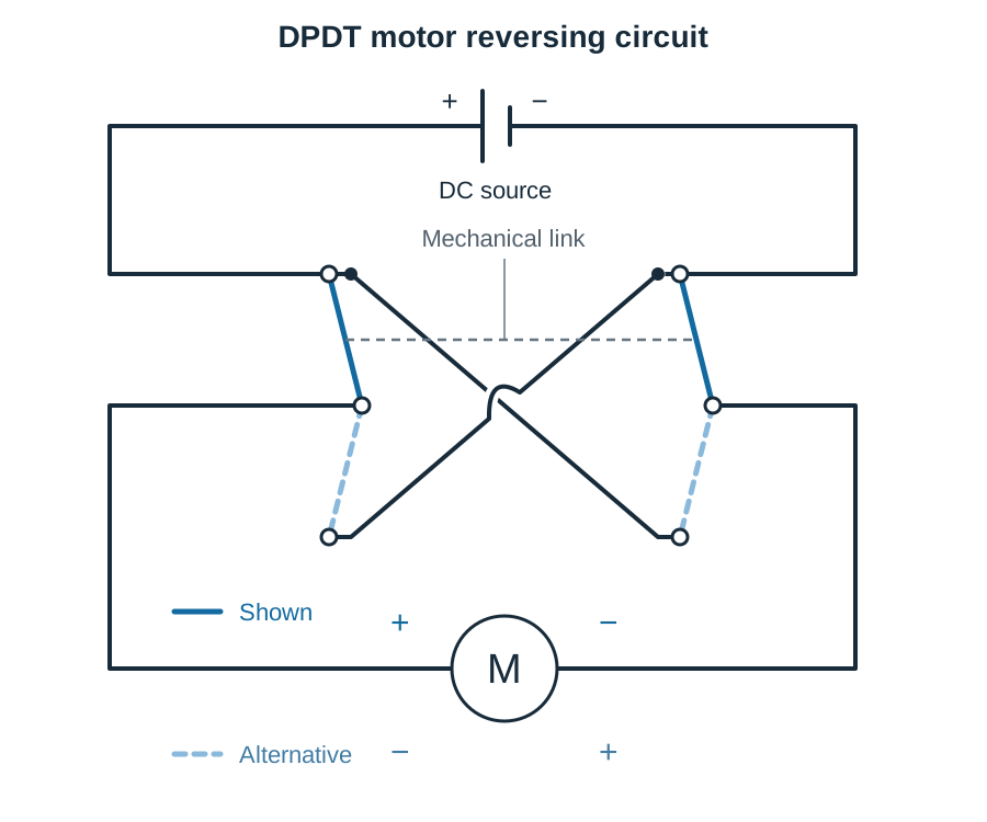
- DPDT Switch: Double-Pole Double-Throw switch. Wired with crossed diagonal jumpers to reverse DC motor polarity for bidirectional drive.
- Microswitch: Placed at track ends to cut motor power automatically when hit, preventing mechanical stalls.
- Light Dependent Resistor (LDR): Resistance drops as light levels rise, forming a sensing potential divider.
- NPN Transistor: Acts as an electronic switch. A small base current switches a larger collector-emitter current to run a motor.
- Flywheel Diode: Wired reverse-biased across a DC motor coil to absorb harmful back-EMF voltage spikes when the motor is switched off.
Testing with Measurements against the Specification
Assemble your mechanisms and test them using real measurements before applying paint. Record numerical findings in an evaluation table:
| Specification Parameter | Test Method | Measured Result | Verdict |
|---|---|---|---|
| Axle speed: 60 ± 5 rpm | Optical tachometer on wheel | 58.2 rpm under full load | Pass |
| Payload: Lift 250 g over 100 mm | Timed vertical lift with test mass | Lifted 100 mm in 2.8 s; current 0.42 A | Pass |
| Motor plate deflection < 0.5 mm | Dial gauge on bracket under stall torque | Deflection measured 0.85 mm; gears slipped | Fail |
Diagnosing Faults and Critical Evaluation
Examiners appreciate honest engineering evaluations. In the failure above, do not conceal the defect. State that the 2 mm aluminium bracket lacked bending stiffness. Explain that adding a folded stiffening flange or a triangular gusset plate deepens the cross-section in the direction of the load, eliminating flex with almost no added weight.
Key terms
- Prototype
- A working physical model built to prove out mechanical, electrical, and structural functions against a design brief.
- Design Function
- The systematic selection of materials, shapes, sizes, and processes to solve a technical problem.
- Velocity Ratio
- The ratio of driver speed to driven speed, calculated as driven gear teeth divided by driver gear teeth.
- Compound Gear Train
- A gear system containing two or more pairs of meshing gears where intermediate shafts carry two fixed gears that turn together.
- Worm and Wormwheel
- A gear pair that achieves a high speed reduction in a single stage and cannot be back-driven by the output shaft.
- Rack and Pinion
- A mechanism consisting of a circular spur gear meshed with a flat toothed bar, used to convert rotary motion into linear motion.
- Crank and Slider
- A mechanism that converts continuous rotary motion into reciprocating linear motion, with a stroke length equal to twice the crank radius.
- Cam and Follower
- A mechanism where a shaped rotating disc imparts a profiled reciprocating or oscillating motion to a contacting follower.
- Mechanical Advantage
- The ratio of the load force overcome by a machine to the effort force applied to it.
- Cutting Speed
- The linear surface speed in metres per minute at which a cutting edge passes across the workpiece.
- Sequence of Operations
- The planned, step-by-step chronological order of workshop manufacturing processes, with practical reasons for each step.
- Datum Edge
- A flat, true reference edge prepared first on a workpiece, from which all subsequent layout measurements and hole positions are marked.
- Key and Keyway
- A demountable joint where a square or rectangular steel key sits in mating slots on a shaft and hub to transmit rotational torque in shear.
- DPDT Switch
- A Double-Pole Double-Throw switch that can reverse circuit polarity to change the direction of a DC motor.
- Flywheel Diode
- A diode connected reverse-biased across an inductive load to dissipate destructive back-EMF voltage spikes when power is removed.
- Back-EMF
- An induced reverse voltage spike produced by an inductive component, such as an electric motor coil, when the current supply suddenly collapses.
- Strength
- The ability of an engineering material to resist permanent plastic deformation or fracture under applied load.
- Stiffness
- The ability of an engineering material or structure to resist elastic deflection or bending when loaded.
- Hardening
- A heat treatment process where carbon steel is heated to cherry-red (above critical temperature) and rapidly quenched in water to form brittle martensite.
- Tempering
- Reheating a hardened steel component to a specific temperature below its critical point to reduce brittleness and restore toughness.
- Annealing
- A heat treatment process involving heating a metal to a specific temperature and cooling it slowly to soften it and relieve internal stresses.
- Martensite
- The extremely hard, needle-like, brittle crystalline structure formed when high carbon steel is quenched rapidly from above its critical temperature.
Check yourself
What are the five basic functions of an engineering project listed under Technology in the Workshop Processes section of the syllabus?
Research, development, design, production, and testing.
Which four specific choices constitute the design function according to the syllabus?
The selection of materials, shapes, sizes, and processes.
A 20-tooth gear must be fixed to an 8 mm drive shaft so that it can be removed for servicing. Name a suitable method and one preparation step on the shaft.
Use a grub screw through the gear boss, and file a small flat on the shaft under the screw so it grips firmly without raising a burr that jams the shaft.
A motor runs at 2400 rpm. Using gears of 12, 24, 36, and 48 teeth, design a two-stage compound train giving an output of 200 rpm, and state the overall velocity ratio.
Required VR = 2400 / 200 = 12 : 1. Stage 1 = 48 / 12 = 4 : 1; Stage 2 = 36 / 12 = 3 : 1. Total VR = 4 × 3 = 12 : 1, giving an output speed of 2400 / 12 = 200 rpm.
A motor turning at 1500 rpm drives a 25 mm pulley belted to a 125 mm pulley on a layshaft. Find the layshaft speed.
VR = d(driven) / d(driver) = 125 / 25 = 5 : 1. Layshaft speed = 1500 / 5 = 300 rpm.
Why must pilot holes be drilled in sheet metal before bending brackets to shape?
Drilling must be done while the sheet is flat because bent brackets cannot be clamped safely or aligned accurately in a drilling vice.
Calculate the spindle speed for an 8 mm drill cutting mild steel at a cutting speed of 24 m/min using N = (1000 v) / (pi d).
N = (1000 × 24) / (π × 8) = 24000 / 25.13 = 955 rpm. The operator should select the nearest available machine speed below 955 rpm.