

Pneumatics is a branch of fluid power engineering that uses compressed air to transmit force, drive mechanical actuators, and automate control systems. In Leaving Certificate Engineering, pneumatics is part of Control Technology in Appendix 1 of the syllabus. Exam questions on Appendix 1 are optional; pneumatics has appeared, for example, in 2025 Higher Level Q9(b)(iv). This guide covers compressed air generation and preparation, pneumatic cylinders, directional control valves, logic elements, circuit diagrams, and force calculations.
Principles of Fluid Power: Pneumatics vs. Hydraulics
Fluid power systems transmit energy through a pressurised fluid enclosed in pipework and actuators. When a fluid is confined, pressure is exerted equally in all directions against the internal walls of its container.
In pneumatics, the working fluid is compressed atmospheric air. Air is a gas, which means it is highly compressible. When an external mechanical load pushes against an extending cylinder, the air inside acts like a cushion or spring. Air is light and flows easily, so pneumatic cylinders move quickly. Because air is compressible, it also gives natural cushioning, but this makes holding a position firmly and accurately difficult under changing loads. Once the air has done its work, it vents straight into the atmosphere through a silencer.
In hydraulics, the working fluid is an incompressible mineral oil or synthetic fluid. Because liquids do not compress noticeably under pressure, hydraulic systems can transmit massive forces and hold a position firmly and accurately, even under heavy load (such as in excavators, vehicle braking systems, and heavy production presses). However, hydraulic fluid cannot be vented to the room. It must flow back through a closed return pipe to a fluid reservoir, and leaks present fire and slipping hazards.
| Feature | Pneumatics | Hydraulics |
|---|---|---|
| Working Fluid | Compressed atmospheric air | Incompressible mineral oil or fluid |
| Compressibility | High (elastic, spring-like cushioning) | Negligible (incompressible, rigid) |
| Force Output | Low to medium | Extremely high |
| Exhaust / Return | Vents directly to the room through a silencer | Closed return pipe to a storage reservoir |
| Cleanliness | Clean; safe for food, packaging, and textiles | Risk of leaks, staining, and contamination |
Compressed Air Supply and the FRL Unit
A pneumatic system begins with air generation and preparation before compressed air reaches any control valves.
Producing the Compressed Air
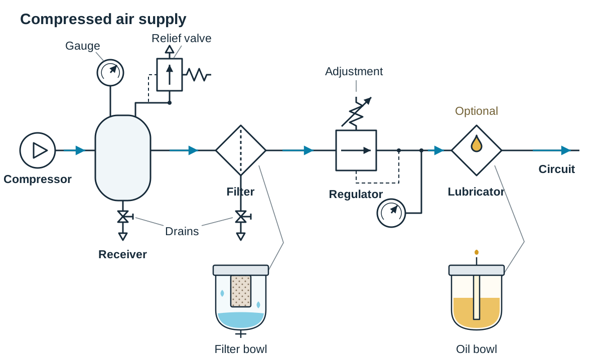
- Compressor: An electric motor drives a piston or rotary compressor that draws in ambient atmospheric air and compresses it into a smaller volume, raising its pressure.
- Receiver: A heavy steel storage vessel that stores a reserve of pressurised air so the compressor motor does not have to run continuously. It dampens pressure pulses from the compressor piston, allows hot compressed air to cool, and collects condensing moisture so it can be drained off.
- Safety Fittings: The receiver is fitted with a pressure gauge, a safety relief valve to discharge air if pressure exceeds safe limits, and a manual drain valve at its base.
Air Preparation: the FRL Unit
Compressed air leaving the receiver can still carry moisture and dirt. Moisture rusts valve spools and steel springs, while fine dust wears away synthetic rubber O-rings. Air must pass through an FRL unit (Filter, Regulator, Lubricator) before entering a machine circuit:
- Filter: Vanes spin the incoming air to fling water droplets and coarse grit outwards against the transparent bowl wall, where they fall to the bottom. The air then passes through a porous sintered bronze or plastic core that catches fine dust particles. A manual drain cock lets collected liquid blow off.
- Regulator: Supply pressure from the compressor fluctuates as demands change. The regulator uses an adjustable control knob, internal spring, and flexible diaphragm to throttle the line down to a constant, stable working circuit pressure (typically ), shown on an integrated dial gauge.
- Lubricator: In systems using dynamic sliding seals, the lubricator atomises a measured mist of light oil into the dry air stream to minimise internal friction and prevent seal breakdown. Modern automated machines often use pre-lubricated components and omit this stage to supply dry, oil-free air.
Pneumatic Actuators: Cylinders and Motors
Pneumatic actuators convert the potential energy of compressed air into mechanical work.
Single-Acting Cylinder (SAC)
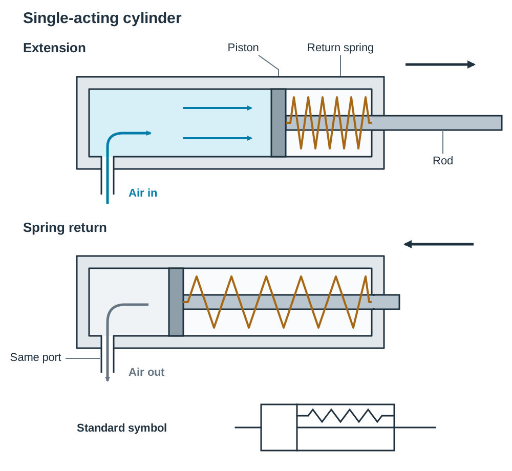
A single-acting cylinder is a pneumatic output device that uses compressed air to produce linear motion in one direction only:
- Compressed air enters a single inlet port at the rear, forcing the piston forward (the power stroke) and compressing an internal mechanical return spring.
- When the directional control valve shifts and vents that port to exhaust, the stored energy in the return spring pushes the piston back to its starting position (the return stroke).
- It performs mechanical work in one direction only.
- Typical applications include light clamping, part ejection from a feed track, and marking or stamping.
Double-Acting Cylinder (DAC)
A double-acting cylinder has two working air ports and no internal spring. It uses compressed air to deliver powered linear work on both the extension and retraction strokes:
- Outstroke (Advance): Compressed air is piped into the rear port behind the piston while the front rod-end port connects to exhaust. The piston rod pushes forward with full force.
- Instroke (Retraction): Air is piped into the front rod-end port while the rear chamber vents to exhaust. Air drives the piston back inward.
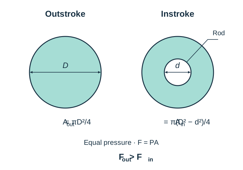
- Annular Area Difference: A standard single-rod double-acting cylinder produces less force on the instroke than on the outstroke at the same line pressure. The steel piston rod passes through the front chamber, taking up space and reducing the surface area against which compressed air can push.
Rotary Actuators
An air motor uses the expansion of compressed air across vanes or pistons to produce continuous rotary motion. Air motors run cool under load, cannot burn out if stalled, and are widely used in hand-held tools such as workshop drills, grinders, and tyre wrenches.
Directional Control Valves (DCVs)
Directional control valves direct, route, or stop compressed air flowing through a circuit. They are identified by two numbers: the number of ports (connections) followed by the number of switching positions.
In standard schematic diagrams, each switching position is drawn as a square box. Inside the boxes, arrows show the flow path between ports, and short T-bars show closed or blocked ports. Actuation mechanisms are drawn at the outer ends of the boxes.
Standard Port Numbering
- Port 1: Main compressed air supply line.
- Ports 2 and 4: Working output lines leading directly to actuators.
- Ports 3 and 5: Exhaust ports open to atmosphere (typically fitted with silencers).
- Ports 12 and 14: Pilot control signal lines. A signal at Port 12 connects supply Port 1 to working Port 2; a signal at Port 14 connects supply Port 1 to working Port 4.
3/2-Way Directional Control Valve
A 3/2 valve has three ports and two switching positions. It is the standard control valve used to operate a single-acting cylinder or to provide a pilot air signal to a larger valve:
- In its unoperated (normally closed) position, an internal spring keeps supply Port 1 blocked, while working Port 2 is open to exhaust Port 3, allowing the cylinder to stay retracted.
- When operated (such as by pressing a push button), the internal spool or poppet shifts: Port 1 connects to Port 2 to pressurise the cylinder, and exhaust Port 3 is closed off.
5/2-Way Directional Control Valve
A 5/2 valve has five ports and two switching positions. It is the standard valve used to control the advance and retreat of a double-acting cylinder. It can be operated by push button, hand lever, mechanical roller trip, solenoid, or pilot signal:
- In position one, supply Port 1 connects to working Port 2 (retracting the cylinder), while working Port 4 vents through exhaust Port 5.
- In position two, supply Port 1 connects to working Port 4 (extending the cylinder), while working Port 2 vents through exhaust Port 3.
- A 5/2 valve with pilot connections at both ends (double-pilot) possesses a memory function. Once shifted by a brief pilot pulse at Port 14, the valve stays in that position even after the pulse stops. It remains there until an opposing pulse arrives at Port 12.
Valve Actuation Methods
- Manual: Push button, hand lever, or foot pedal.
- Mechanical: Roller trip or spring plunger, triggered by a moving cylinder rod or machine carriage.
- Pneumatic: A pilot signal sends a small volume of air from a remote 3/2 valve to shift the spool.
- Electrical: A solenoid coil magnetises an internal armature to switch the valve using a signal from a microswitch, sensor, or programmable logic controller.
Pneumatic Logic and Speed Regulation
Automation systems combine specialised logic valves and flow restrictors to create reliable control sequences.
Shuttle Valve (OR Logic)
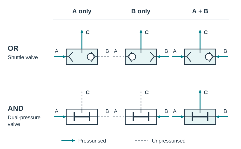
A shuttle valve has two inlet ports and one central outlet port, with a floating rubber or metal ball inside. When compressed air enters either inlet, the ball is blown across to seal the opposing inlet, letting air flow out through the central port. This provides OR logic. It is used whenever an operation must be triggered from either of two separate locations, such as opening an automated bus door from a switch on the dashboard OR a push button on the outside.
Dual-Pressure Valve (AND Logic)
A dual-pressure valve has two inputs and one common output. If air enters only one inlet, an internal stepped spool slides across and blocks the air from reaching the outlet. Air passes to the outlet only while both inputs are pressurised at the same time. If either input drops to zero, the output signal is lost. This provides AND logic. Its primary workshop application is two-hand safety control: the machine operator must hold down two separate push-button valves simultaneously (one with each hand, kept well clear of the danger zone) before a guillotine or power press is permitted to cycle.
Speed Regulation: Throttle Check Valves
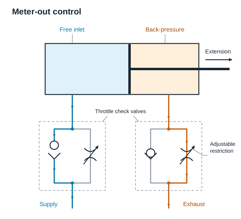
A throttle check valve (one-way flow restrictor) contains an adjustable needle valve alongside a spring-loaded non-return check ball. Air travelling in one direction is forced through the narrow needle opening (restricted flow). Air travelling in the opposite direction lifts the ball off its seat and flows through without restriction.
- Double-Acting Speed Control (Meter-Out): Regulating cylinder speed is best done using meter-out control. The throttle check valve is piped so that air entering the cylinder flows freely through the check ball, but exhaust air escaping from the opposite chamber is throttled through the needle. Because air compresses, restricting the escaping exhaust builds a steadying back-pressure cushion. This cushion prevents the piston from lurching forward when cutting tools bite or loads change suddenly.
- Single-Acting Speed Control: Because a single-acting cylinder has only one air line, both strokes share the same pipe. To slow the outstroke, fit the valve so incoming air is restricted while return exhaust flows freely. To slow the spring-return instroke, reverse the valve so outgoing exhaust air is restricted.
Circuit Symbols and Basic Circuits
To read and complete pneumatic circuit drawings, you need to recognise the standard symbols:
- Air Supply: A small circle with a central triangle or dot pointing in the flow direction.
- Exhaust Port: A small open triangle pointing outward. If fitted with a silencer, a small rectangle is added.
- Single-Acting Cylinder: A rectangle showing a piston, piston rod, single rear air port, and an internal zig-zag return spring.
- Double-Acting Cylinder: A rectangle showing a piston and rod with two connection ports and no internal spring.
- Directional Valves: Two adjacent squares. Arrows show airflow paths, and T-bars show blocked ports. Actuators appear on the ends: push button (semicircle on a stem), lever (angled line), roller trip (circle on a stem), spring return (zig-zag line), solenoid (box with a diagonal line), and pilot line (dashed line).
- Throttle Check Valve: A restricted path with an adjustment arrow in parallel with a ball-and-seat check valve.
Direct Control of a Single-Acting Cylinder
In direct control, the valve operated by the user pipes working air straight into the actuator:
- Components: Air supply, 3/2 push-button valve with spring return, single-acting cylinder.
- At rest: The valve spring blocks supply Port 1. Cylinder Port 2 vents through exhaust Port 3, so the piston remains retracted.
- Operating: Pressing the push button shifts the spool, connecting Port 1 to Port 2. Compressed air enters the cylinder and drives the piston forward, compressing the return spring.
- Releasing: When the button is released, the valve spring returns the spool. Port 1 is blocked, Port 2 vents through Port 3, and the compressed cylinder spring pushes the piston back to its starting position.
Indirect Control of a Double-Acting Cylinder
In indirect control, small operator-controlled valves send pilot air signals to shift a larger directional control valve:
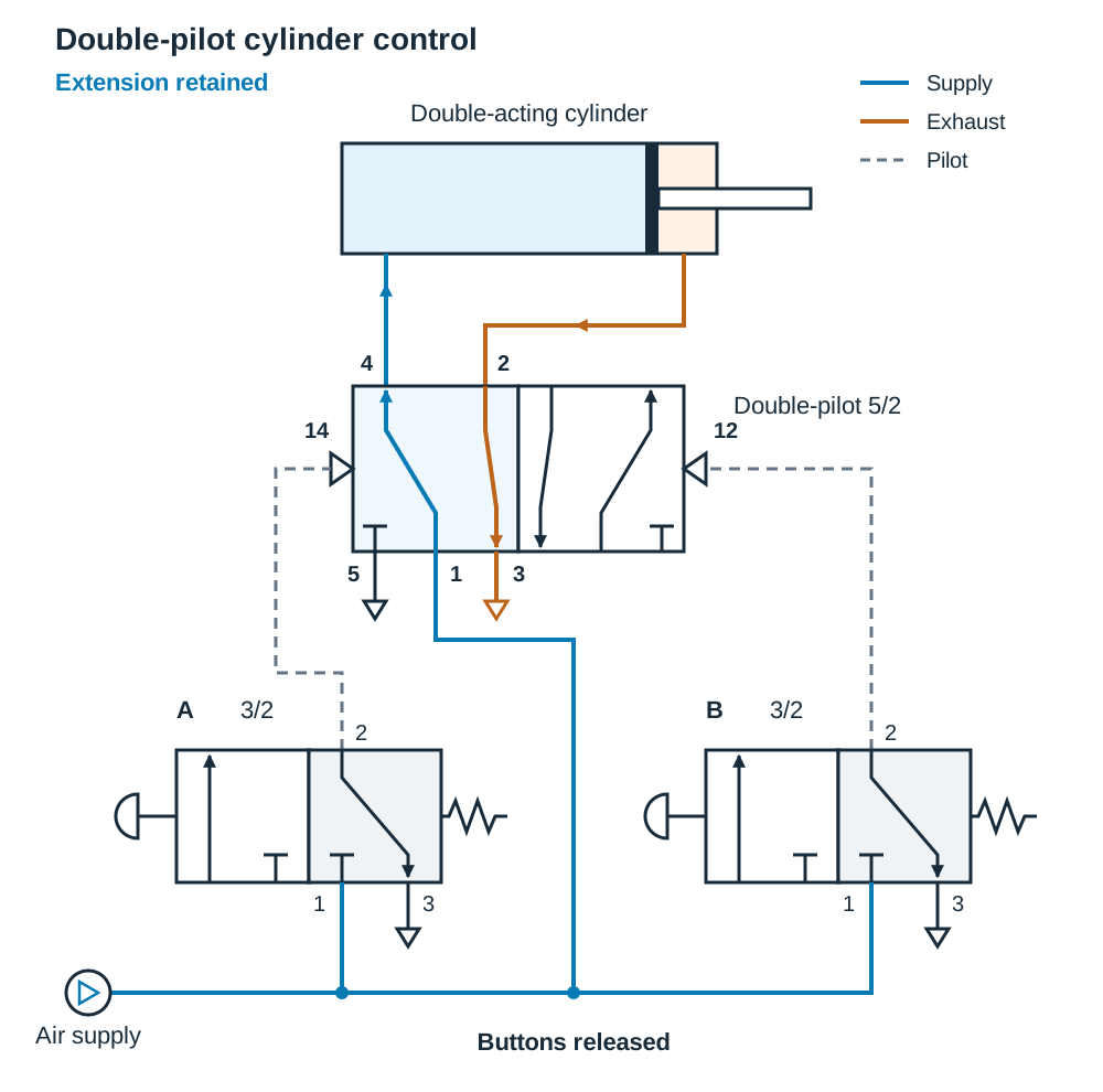
- Components: Air supply, two 3/2 push-button valves (A and B), a double-pilot 5/2 valve, and a double-acting cylinder.
- Extending: The operator taps button A. A pilot pulse enters Port 14 of the 5/2 valve. The spool shifts, routing supply Port 1 to working Port 4 to advance the cylinder, while front air exhausts from Port 2 through Port 3.
- Memory: When button A is released, the pilot signal drops, but the double-pilot 5/2 valve stays in position. The cylinder remains extended.
- Retracting: Tapping button B sends a pilot pulse into Port 12. The spool shifts back, connecting Port 1 to Port 2 to retract the cylinder, while rear air exhausts from Port 4 through Port 5.
Automatic Return Using a Roller Trip
Replace button B with a 3/2 roller-trip valve mounted at the cylinder's full extension point:
- The operator taps button A, pulsing Port 14 so the cylinder advances.
- At full stroke, a trip cam on the piston rod depresses the roller.
- The roller-trip valve sends a pilot pulse to Port 12 of the 5/2 valve, shifting the spool and automatically retracting the cylinder without further operator input.
Pneumatic Force Calculations
The theoretical thrust or pull produced by a cylinder depends on air pressure and working surface area:
Where:
- = Theoretical output force in newtons ()
- = Air pressure in pascals ( or ), or in
- = Effective cross-sectional working area in square metres () or square millimetres ()
Convenient Workshop Units
Working in millimetres and simplifies calculations because directly:
Cylinder Surface Areas
- Outstroke Working Area ():
Compressed air acts over the full circular face of the piston:
where is the internal cylinder bore diameter.
- Instroke Annular Area ():
For a double-acting cylinder, the piston rod takes up part of the front chamber. Air can only act on the ring-shaped area around the rod, known as the annular area:
where is the piston rod diameter.
Unless an exam question specifies a mechanical friction figure or efficiency percentage, calculate theoretical output force directly from the given dimensions and pressure. If an efficiency is given (for example, ), multiply the theoretical force by that factor ().
Workshop Health and Safety
Compressed air systems store substantial energy and present clear workshop hazards that require strict safety practices:
- Compressed air must never be pointed at any person, nor used to blow swarf, filings, or dust off skin or clothing. High-pressure air can be forced through the skin, enter the bloodstream and cause an air embolism, which can be fatal.
- Safety spectacles must always be worn. Escaping high-velocity air streams can throw chips of swarf and abrasive grit into the eyes.
- Venting exhaust ports must be fitted with silencers (porous sintered brass or plastic fittings) to muffle noise and protect hearing.
- Switching off an electric compressor does not vent the circuit. Trapped air downstream can hold cylinders under load, causing sudden movement during maintenance. Circuits must include a lockable three-port isolation dump valve that vents trapped air to atmosphere before servicing.
- Air lines must be firmly secured. A loose, pressurised hose can whip violently. Moving cylinder linkages must be guarded (for example, with a fixed mesh guard or an interlocked guard that stops the machine when opened) to prevent crush injuries.
Key terms
- Pneumatics
- The branch of engineering that uses compressed atmospheric air to transmit power and control mechanical movements.
- Single-Acting Cylinder
- A pneumatic output device that uses compressed air to produce linear motion in one direction (power stroke) and returns using an internal mechanical spring.
- Double-Acting Cylinder
- A pneumatic actuator that uses compressed air on both sides of a piston to deliver powered linear movement on both extension and retraction strokes.
- 3/2 Valve
- A directional control valve with three ports and two switching positions, used to operate single-acting cylinders or deliver pilot air signals.
- 5/2 Valve
- A directional control valve with five ports and two switching positions, used as the main control valve to extend and retract double-acting cylinders.
- Shuttle Valve
- A pneumatic logic valve that directs air to an output if pressure enters either of its two inlet ports, providing an OR logic function.
- Dual-Pressure Valve
- A pneumatic logic valve that delivers an output signal only while both inlet ports receive compressed air simultaneously, providing an AND logic function.
- Throttle Check Valve
- A flow-regulating valve that restricts airflow through an adjustable needle in one direction while allowing free return flow through an internal check valve.
- Meter-Out
- A speed-control method where exhaust air leaving a cylinder is restricted, creating a steadying back-pressure cushion that prevents erratic movement.
- FRL Unit
- An air preparation assembly containing a filter, pressure regulator with gauge, and lubricator to condition compressed air before it enters valves.
- Direct Control
- A circuit arrangement where the valve operated by the user connects supply air straight into the actuator.
- Indirect Control
- A circuit arrangement where small, manually operated valves send pilot air signals to shift a larger directional control valve that powers the cylinder.
- Memory Function
- The ability of a double-pilot directional control valve to stay in its last switched position after the pilot signal has been removed.
- Annular Area
- The effective working surface area on the rod side of a double-acting cylinder piston, calculated by subtracting the rod area from the full bore area.
Check yourself
In an indirect control circuit, an operator presses and releases button A. Why does the double-acting cylinder stay fully extended?
The double-pilot 5/2 valve has a memory function. Once shifted by pilot port 14, its internal spool remains in that position until an opposing pilot signal arrives at port 12.
Why is exhaust air from a pneumatic valve permitted to vent directly into the workshop room, whereas hydraulic fluid cannot?
Pneumatics uses air, which is non-toxic and freely available in the atmosphere. Hydraulic systems use oil, which is expensive, messy, combustible, and creates severe environmental and slipping hazards if released.
What logic function does a shuttle valve perform, and give one practical transport or workshop application.
A shuttle valve performs an OR logic function. A practical application is opening an automated bus door using either a dashboard switch OR an external push button.
A cylinder has a bore diameter of 50 mm and runs on 5 bar line pressure (0.5 N/mm²). Calculate the theoretical forward thrust. (Take π = 3.142).
Piston area A = π × D² / 4 = 3.142 × 2500 / 4 = 1963.75 mm². Thrust force F = P × A = 0.5 N/mm² × 1963.75 mm² = 981.9 N.