

A mechanism is a set of parts that takes the motion and force from a motor or engine and changes it into the motion and force needed at the output, for example faster, slower, stronger, or in a different direction. In Leaving Certificate Higher Level Engineering, the study of mechanisms examines how power is transferred and controlled across gear trains, friction clutches, universal joints, ratchets, lifting linkages, and electromechanical stepper motors.
Mechanical Motion and the Speed-Torque Trade-Off
Mechanical systems handle four primary types of motion:
- Rotary motion: continuous turning movement around a fixed axis, such as an electric motor shaft or lathe spindle.
- Linear motion: movement in a straight line, for example a conveyor belt carrying a box or a robotic gantry slide.
- Reciprocating motion: continuous back-and-forth travel in a straight line, seen in engine pistons, shaping machines, or hacksaw blades.
- Oscillating motion: repetitive swinging back and forth along an arc about a central pivot point, like a clock pendulum or vehicle windscreen wiper.
Power transmission depends on the speed-torque trade-off. An electric motor typically delivers high rotational speed (measured in rev/min) but relatively low turning force (torque, measured in newton-metres, ). Mechanical power is defined by the formula:
In this formula, represents rotational velocity in radians per second. When rotational speed is given as in rev/min, mechanical power is calculated using:
For example, an input shaft delivering a torque of at produces a power output of:
Ignoring friction, gear reduction trades high input speed for a slower output speed that delivers higher torque. Stepping speed up does the opposite: it trades torque for higher shaft speed. An example is a commercial wind turbine, where the massive rotor blades turn slowly under high aerodynamic torque (around 15 rev/min). A step-up gearbox increases this rotational speed to roughly 1,500 rev/min to drive the electrical generator efficiently.
Spur Gears, Idlers, and Gear Train Calculations
Gears are toothed wheels that mesh together to transfer positive mechanical drive without slipping. Meshing gears must have the same tooth size (the same module, and therefore the same pitch).
Spur Gears
Spur gears have teeth cut straight and parallel to the shaft axis. They connect parallel shafts, offer high mechanical efficiency, and are straightforward to manufacture. However, they generate noise and vibration at high speeds because contact occurs suddenly across the full width of each meshing tooth.
When two spur gears mesh directly, the driven gear turns in the opposite direction to the driver gear. Placing an intermediate idler gear between them reverses the rotation so the driven gear turns in the same direction as the driver gear. An idler gear changes only the direction of rotation; it does not change the overall velocity ratio.
Velocity Ratio and Gear Ratios
The gear ratio (or velocity ratio) compares the number of teeth on the driven gear to the driver gear, which relates inversely to shaft speed:
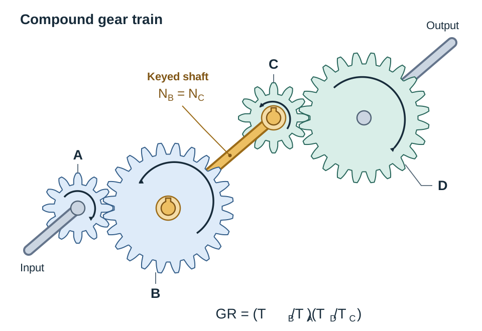
In a compound gear train, two gears of different tooth counts are keyed to the same intermediate shaft and spin at the exact same speed. The total gear ratio is the product of the individual reduction stages:
Specialised Gear Arrangements
Different gear setups alter the relative angle of the shafts or convert rotational drive into straight-line movement.
Worm and Worm Wheel
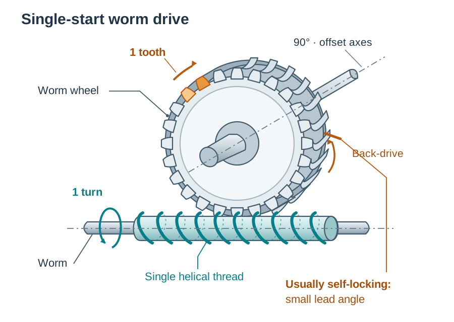
A cylindrical threaded screw (the worm) meshes with a worm wheel, which is a gear cut with curved teeth that envelope the worm. The shafts sit perpendicular () without intersecting.
The velocity ratio is calculated from the wheel teeth and the number of starts on the worm:
A single-start worm moves the wheel on by one tooth per turn. A two-start worm moves it on by two teeth per turn. For example, if a single-start worm drives a 40-tooth worm wheel at an input speed of , the velocity ratio is . The wheel speed is . If a two-start worm were used instead, the velocity ratio would be , giving an output speed of .
A single-start worm drive with a small lead angle is usually self-locking. The worm turns the wheel easily, but friction stops a load on the wheel from turning the worm backwards. Multi-start worms with a steep thread may not self-lock.
Rack and Pinion
A circular gear (the pinion) meshes with a flat, straight toothed bar (the rack). This mechanism converts rotary motion into linear motion, or linear motion back into rotary motion. Common examples include vehicle steering racks, workshop pillar drill feeds, and stairlifts.
Bevel Gears
Bevel gears are conically shaped gears with teeth machined along an angled face. They transmit rotary motion between intersecting shafts, typically oriented at , such as in hand drills and vehicle differentials.
Single-Plate Friction Clutches
A clutch is a mechanical coupling that temporarily connects and disconnects two in-line shafts at will. Positioned between the engine and the gearbox, it allows an engine to idle while stationary, enables smooth gear changes, and allows a gradual pickup of drive through controlled friction slip.
Key Components
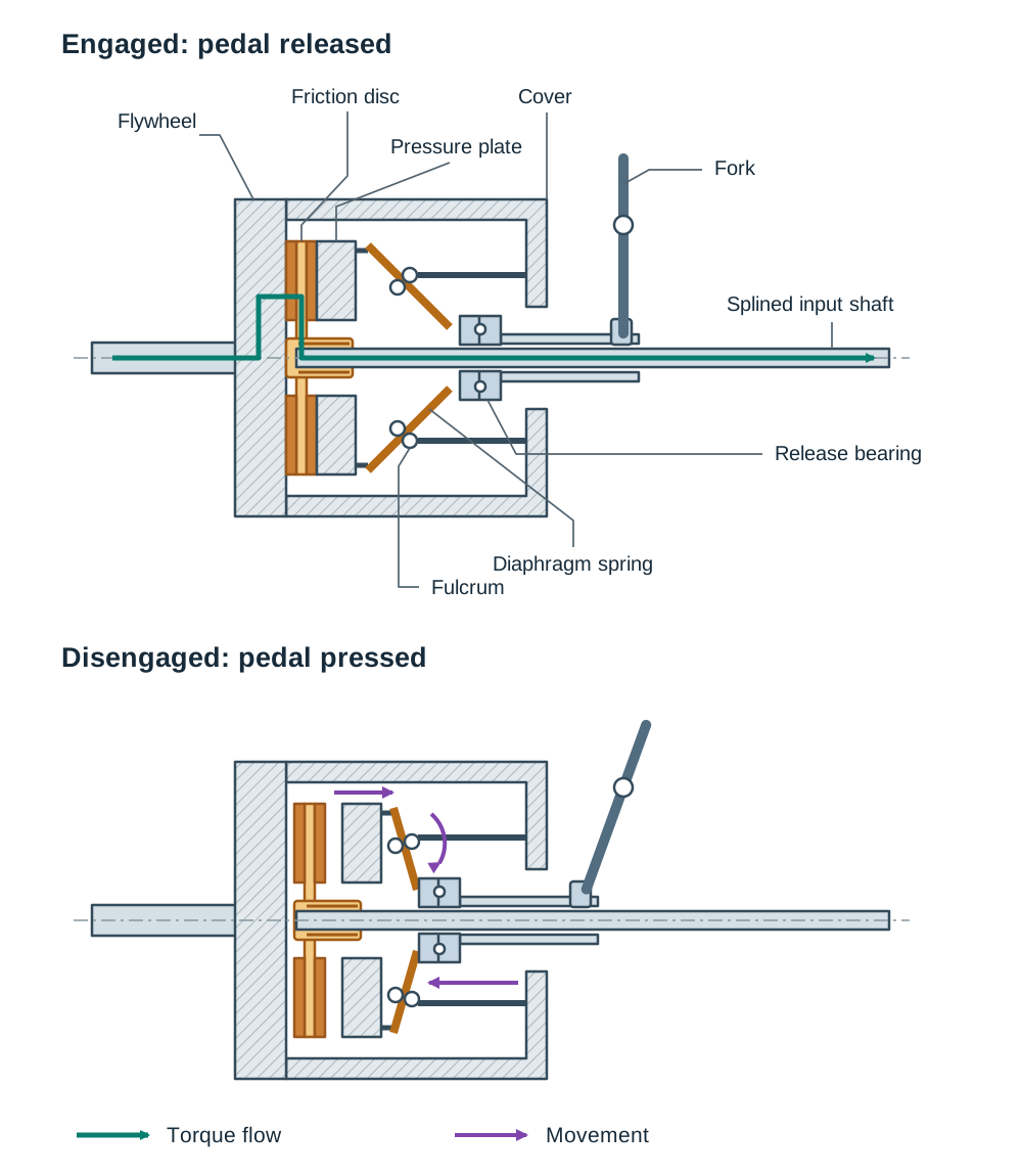
- Flywheel: a heavy steel or cast-iron disc bolted to the engine crankshaft that stores kinetic energy to smooth out engine power, and provides one of the friction faces that drives the clutch disc.
- Clutch Cover: bolted securely to the outer rim of the flywheel, housing the diaphragm spring and pressure plate so that they rotate at engine speed.
- Clutch Friction Disc: a steel plate splined onto the gearbox input shaft. It carries heat-resistant friction linings on both faces, along with central torsion springs to absorb sudden rotational shocks.
- Pressure Plate: a heavy cast iron ring inside the cover that clamps the friction disc against the flywheel face.
- Diaphragm Spring: a dished circular spring-steel plate that exerts continuous axial clamping force when the clutch is engaged.
- Release Bearing and Fork: a thrust bearing moved by a pivoted lever connected to the driver's clutch pedal.
Operational Sequence
Disengaging the clutch (pedal pressed down):
- The driver presses the clutch pedal, pivoting the release fork.
- The fork pushes the release bearing forward against the centre fingers of the diaphragm spring.
- The diaphragm spring pivots on its fulcrum rings, causing its outer circumference to pull backward.
- This withdraws the pressure plate away from the clutch friction disc.
- The friction disc is freed from clamping force, disconnecting drive so that the gearbox input shaft stops turning with the engine.
Engaging the clutch (pedal released):
- The driver releases the pedal, pulling the release bearing back.
- The diaphragm spring snaps back into its dished resting shape.
- The spring forces the pressure plate firmly against the friction disc.
- The disc is clamped tightly against the spinning flywheel face.
- Static friction locks the assembly, driving the gearbox input shaft at engine speed.
Universal Joints and Power Take-Off Shafts
A universal joint (Cardan or Hooke's joint) connects two rotating shafts whose axes intersect at an angle, allowing drive to continue while that operating angle shifts dynamically.
Construction and Working Principle
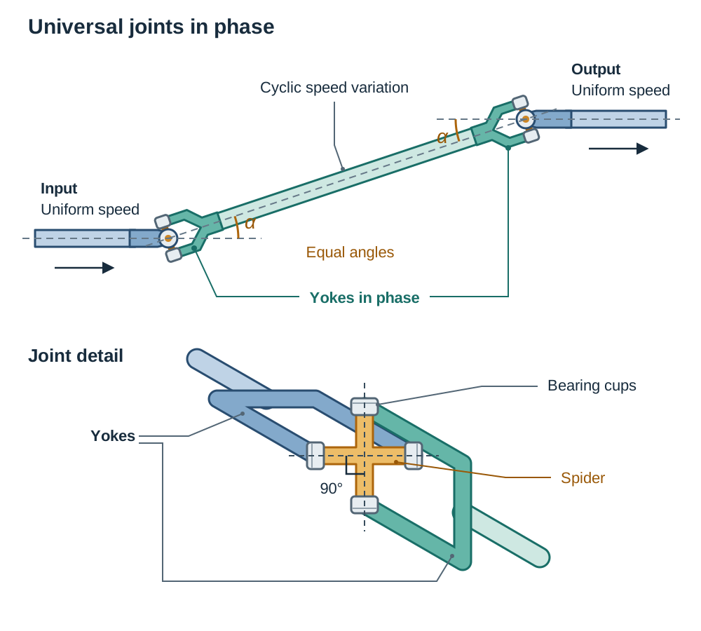
A universal joint consists of two forged steel yokes attached to the shaft ends, linked by a central four-armed cross shaft called a spider. Each trunnion on the spider sits in needle roller bearings held within bearing cups in the yoke eyes. Because the two pivot axes sit at to each other, the joint can bend to any angle (within its operating limit) while still transmitting torque.
A single universal joint operating through an angle does not produce constant angular velocity; the driven shaft accelerates and decelerates twice during every complete revolution. To eliminate this vibration:
- Universal joints must be installed in pairs, one at each end of the intermediate shaft.
- The operating angle at both joints must be equal.
- The two inner yokes on the intermediate shaft must lie in the same plane (yokes in phase).
When these conditions are met, the cyclic speed variation created by the first joint is cancelled out by the second joint, producing a smooth, uniform output rotation.
Agricultural Power Take-Off (PTO) Shaft
A common example is the tractor Power Take-Off (PTO) shaft. Another is the propeller shaft of a rear-wheel-drive vehicle. As a tractor pulls an implement like a baler or slurry tanker over uneven ground or turns corners, the relative angle and distance between the tractor output spline and the machine input shaft constantly change. Universal joints at each end absorb the angular changes, while a telescopic splined shaft slides in and out to accommodate changes in working length.
Directional Control and Lifting Mechanisms
Ratchet and Pawl Mechanism
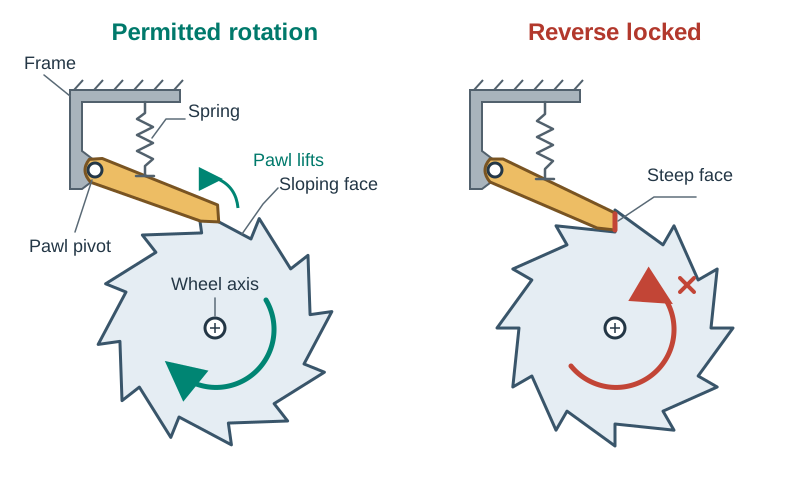
A ratchet and pawl permits rotation in one direction while positively locking movement in reverse.
- Ratchet Wheel: a wheel cut with asymmetric teeth featuring a gently sloping face on one side and a steep locking face on the other.
- Pawl: a pivoted finger held against the teeth by a spring or gravity.
When the wheel rotates forward, the pawl rides up and clicks over the gently sloping faces. If reverse torque is applied, the pawl drops squarely against the steep face, jamming the wheel instantly. Common applications include winches, tie-down ratchet straps, socket wrenches, and security turnstiles.
Scissor Lift Mechanism
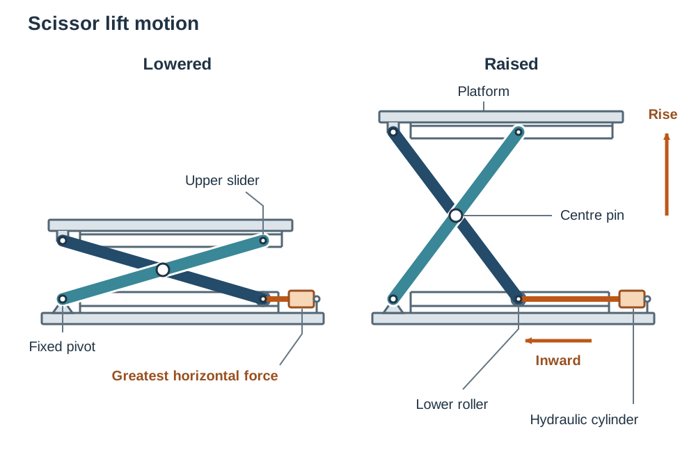
A scissor lift raises a platform using pairs of crossed arms, pinned at their centres in an 'X' shape, that extend upwards as the base is pushed together. One lower pivot is pinned to the base frame, while the opposing lower pivot has rollers that slide along a horizontal guide channel. When an actuator (typically a hydraulic cylinder) pushes the sliding pivot inward, the crossed arms fold upward, raising the platform smoothly.
The horizontal force required from the cylinder is greatest when the platform is fully lowered, because the scissor arms are nearly flat and mechanical leverage is lowest.
Alternative Platform Lifting Mechanisms
Where a scissor lift is not suitable for raising a load or wheelchair platform, common mechanical alternatives include:
- Lead screw (screw drive): an electric motor turns a threaded vertical rod. A captive nut fixed to the lifting platform travels up or down the thread. Because of its small lead angle, a screw drive is typically self-locking, preventing the platform from dropping if power fails.
- Rack and pinion: an electric motor drives a rotating pinion gear that climbs up a vertical toothed rack secured to a guide pillar, commonly seen in mobility stairlifts.
- Cable and pulley (winch): an electric motor rotates a winding drum that reels in a high-tensile steel wire rope routed over guide pulleys to raise the carrier frame. It requires an auxiliary safety brake or ratchet mechanism to arrest the load if the cable slacks.
Stepper Motors and Digital Actuation
A stepper motor is an electromechanical actuator that converts digital electrical pulses into precise, incremental mechanical steps, rather than spinning continuously like a conventional DC motor.
Internal Construction and Operation
The central rotor consists of a permanent magnet (often machined with fine teeth) surrounded by a ring of electromagnetic stator coils. When the controller delivers current to a pair of coils, it establishes an electromagnetic field. The rotor snaps into alignment with this field. By energising the stator coils sequentially, the rotor is pulled around one step at a time.
Operating Principles
- Pulse count: determines the total shaft rotation angle. Each pulse moves the motor through one fixed step angle (typically , requiring 200 pulses for one full turn).
- Pulse frequency: determines the rotational speed of the shaft. Increasing the frequency (pulses per second or ) increases the shaft speed.
- Pulse sequence: determines the direction of rotation. Reversing the coil firing order (such as switching from to ) reverses rotation from clockwise to anticlockwise.
Advantages and Limitations
Stepper motors provide accurate open-loop position control, meaning the controller knows the position simply by counting the pulses it has sent, without needing costly optical feedback encoders. They deliver high torque at low operating speeds and provide excellent holding torque to hold a load locked in position when stationary. Because they have no internal carbon brushes to wear out, they are reliable and long-lasting.
However, if the mechanical load exceeds motor capacity or the pulse frequency is ramped up too quickly, the motor can miss steps. In an open-loop circuit, the controller has no way of detecting lost steps, leading to positioning errors.
Key terms
- Gear Ratio
- The ratio of teeth on the driven gear to teeth on the driver gear, which dictates speed change and torque multiplication.
- Idler Gear
- An intermediate gear placed between a driver and driven gear to reverse output direction without altering the velocity ratio.
- Worm Wheel
- A toothed gear wheel with concave teeth designed to mesh with a perpendicular worm screw.
- Number of Starts
- The number of individual helical threads wrapped around the cylindrical body of a worm screw.
- Self-Locking
- A mechanical condition where friction prevents the driven element from back-driving the input component under reverse load.
- Pinion
- A small circular toothed gear that meshes with a flat rack, a larger gear, or a differential ring gear.
- Rack
- A flat, straight bar with gear teeth machined along its length that converts rotary drive into linear displacement.
- Diaphragm Spring
- A dished circular spring-steel disc in a friction clutch that supplies continuous axial clamping pressure against the pressure plate.
- Universal Joint
- A four-point cross coupling that transmits rotary motion between two shafts whose axes intersect at an angle.
- Telescopic Splined Shaft
- A two-piece sliding drive shaft that transfers continuous torque while extending or retracting to accommodate changing working distances.
- Yokes in Phase
- The exact alignment of the two inner universal joint forks on an intermediate shaft in the same plane to cancel cyclic rotational speed variations.
- Ratchet and Pawl
- A directional mechanism consisting of an asymmetric toothed wheel and a spring-loaded catch that permits rotation in one direction only.
- Scissor Lift
- A lifting linkage using crossing, centre-pinned beams in an 'X' arrangement to convert horizontal inward thrust into vertical elevation.
- Stepper Motor
- An electromechanical actuator that converts digital electrical pulses into precise, discrete mechanical steps.
- Step Angle
- The fixed angular displacement traversed by a stepper motor rotor for each individual electrical pulse received.
- Holding Torque
- The maximum static turning moment an energised, stationary stepper motor can resist before slipping out of position.
Check yourself
A 20-tooth driver gear rotates at 900 rev/min and meshes with a 60-tooth driven gear. Find the gear ratio and the output speed.
Gear ratio = 60 / 20 = 3:1. Output speed = 900 / 3 = 300 rev/min.
What is the primary function of an idler gear in a spur gear train?
It reverses the direction of rotation of the driven gear so it turns in the same direction as the driver, without changing the overall velocity ratio.
Under what condition is a worm and worm wheel drive self-locking?
When it has a single-start worm with a small lead angle, where friction prevents the wheel from driving the worm in reverse.
What component in a single-plate clutch provides the axial clamping force to press the friction disc against the flywheel?
The diaphragm spring.
What two conditions must be met for a pair of universal joints to cancel speed variations across an intermediate shaft?
The operating angles at both joints must be equal, and the inner yokes on the intermediate shaft must lie in the same plane (in phase).
Why is the force required to lift a scissor platform greatest when the platform is fully lowered?
Because the scissor arms are nearly flat, giving poor mechanical leverage for the horizontal actuator.
How do you reverse the rotational direction of a stepper motor?
By reversing the electrical firing sequence sent to the stator coils.
Name two mechanical alternatives to a scissor lift for raising a platform.
A motorized lead screw (screw drive) and a rack and pinion drive (or cable and winch).