

Machining and metrology form the foundation of precision manufacturing in Leaving Certificate Engineering. Machining uses machine tools such as the centre lathe, milling machine, shaping machine, precision grinder, and Computer Numerical Control (CNC) equipment to shape metal by controlled chip removal. Metrology provides the science of measurement, dimensional tolerances, limits and fits, and precise angular inspection. Together, they ensure that independently made components fit and function reliably in modern assemblies.
Centre Lathe Construction, Tool Geometry & Operations
On a centre lathe, the workpiece rotates while a single-point cutting tool moves along or across it to remove material. The machine size is defined by its specification: the height of centres (or swing over the bed, the largest diameter that can turn clear of the bed) and the distance between centres (the maximum length of work held between headstock and tailstock centres).
Main Lathe Assemblies
- Headstock: houses the driving motor, speed-change gearbox, and hollow spindle that rotates the work.
- Bed: rigid, precision-ground slideways that align the carriage and tailstock.
- Saddle and carriage: traverses longitudinally along the bed, either manually or by power feed via the feed shaft or leadscrew.
- Cross-slide: moves the cutting tool perpendicular to the lathe centreline to face ends or set depths of cut.
- Top slide (compound slide): sits on the cross-slide and swivels on a graduated base to machine short, steep angles and tapers.
- Tailstock: slides along the bed to support long work with a revolving centre, or holds drills, reamers, and chucks in its Morse taper quill.
Tool Geometry and Forces on the Cutter
When a single-point tool cuts, the workpiece resists with forces in three planes:
- Tangential force (cutting force): acts vertically downward on top of the tool tip. It is the largest force and accounts for almost all the power consumed.
- Axial force (feed force): acts parallel to the workpiece axis, resisting the carriage feed.
- Radial force: acts along the tool shank, trying to push the tool away from the workpiece.
Tool geometry balances sharpness against strength:
- Rake angle: controls how easily the chip shears along the shear plane and flows away. A positive rake tilts down and away from the cutting edge, reducing cutting forces and heat. It is used with High-Speed Steel (HSS) on ductile metals like mild steel and aluminium. A negative rake slopes upward from the edge; it gives a blunter but much stronger wedge. It is used for hard or brittle materials, interrupted cuts, and with tungsten carbide inserts, which are very hard but brittle. A zero rake is used on brass to prevent the cutting tool from digging in.
- Clearance angle: ground directly below the cutting edge to stop the tool flank rubbing against the revolving workpiece.
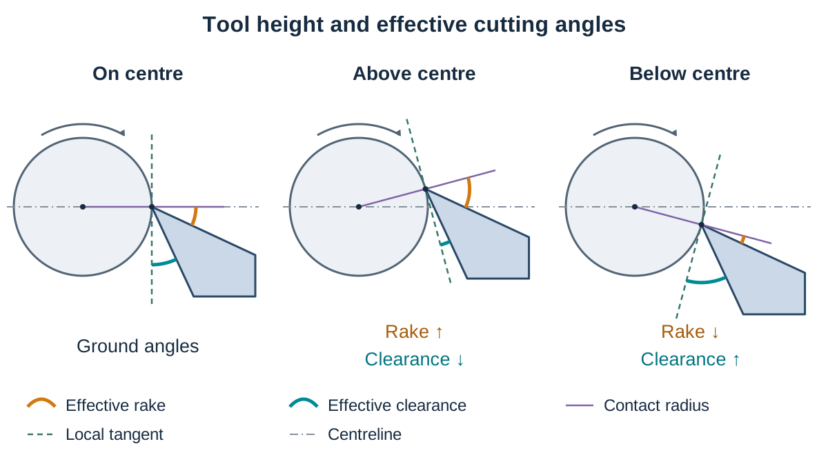
Tool Height Alignment
The tool tip must be set dead on the horizontal centreline of the workpiece:
- Tool on centre: both rake and clearance angles operate at their intended manufactured values.
- Tool above centre: the effective front clearance angle decreases toward zero or becomes negative. The tool flank rubs against the work, generating severe friction, excessive heat, poor surface finish, and tool chatter. Setting the tool above centre also increases the effective rake angle.
- Tool below centre: the effective rake angle decreases, changing the keen cutting action into a scraping action that increases cutting forces. The clearance angle increases, leaving the cutting edge unsupported and prone to chipping. Setting the tool off centre (above or below) leaves an uncut central pip on the end face during facing because the cutting edge cannot reach the true axis of rotation.
Primary Lathe Operations
- Facing: feeding the tool across the end face using the cross-slide to produce a flat datum face and set the part to length. (What to draw: end of bar held in chuck, tool at right angles feeding across the end face, rotation arrow on workpiece.)
- Parallel turning: feeding the tool parallel to the spindle axis using the carriage to reduce diameter uniformly along a length. (What to draw: cylindrical bar in chuck, tool cutting along the outside diameter, feed arrow parallel to the centreline.)
- Parting-off: feeding a narrow blade square to the workpiece axis to cut off a finished part from bar stock.
- Boring: enlarging and truing an existing drilled hole using a boring bar held in the toolpost.
- Knurling: pressing hardened, patterned knurling wheels firmly against the rotating workpiece at low speed to cold-form a diamond or straight textured grip. (What to draw: bar gripped in chuck, knurling tool holder with two serrated rollers pressed into the side face.)
- Eccentric turning: turning a diameter that does not share the main centreline of the workpiece (such as crankshaft journals and engine cams), typically set up in a four-jaw independent chuck.
- Undercutting: a narrow groove cut with a parting-type tool at the end of a thread or shoulder. It gives the screwcutting tool room to finish its run and lets a mating part seat fully against the shoulder.
Lathe Work Holding
Workpieces must be held securely against cutting forces to prevent slipping, vibration, and dangerous deflection.
Chucks and Collets
- Three-jaw self-centring chuck: all three jaws move together through an internal scroll mechanism operated by a single chuck key. It quickly centres round and hexagonal stock.
- Four-jaw independent chuck: each jaw moves independently on its own leadscrew. This allows irregular castings and square stock to be clocked dead true using a Dial Test Indicator (DTI), and allows deliberate off-centre mounting for eccentric turning.
- Collet chuck: uses hardened, spring-steel slotted sleeves that close uniformly around precision bar stock. It provides exceptional grip concentricity and rapid clamping for production runs, but each collet fits only one specific nominal diameter.
Work Between Centres and Steadies
Slender shafts flex under the pressure of the cutting tool. Turning work between centres using a driving plate, carrier dog, and tailstock centre ensures concentricity even if the work is removed and remounted.
- Fixed steady: clamps directly to the bed slideways and uses three adjustable brass or ball-bearing fingers to support the free outer end of long work, allowing end-drilling, boring, or facing without tailstock support.
- Travelling steady: bolts directly to the saddle carriage right behind the cutting tool, moving along with the tool to prevent slender shafts from bowing under tool pressure.
Taper Turning Methods & Screwcutting
A taper is a uniform change in diameter along the length of a component.
Comparison of Taper Turning Methods
| Method | Length of Taper | Steepness (Angle) | Feed Type |
|---|---|---|---|
| Top slide swivel | Short (limited by top slide travel) | Steep or shallow (up to ) | Hand feed only |
| Tailstock offset | Long (full distance between centres) | Very shallow (typically ) | Automatic longitudinal feed |
| Taper attachment | Long (limited by guide bar) | Moderate angles (typically up to ) | Automatic longitudinal feed |
Top Slide Angle Calculation
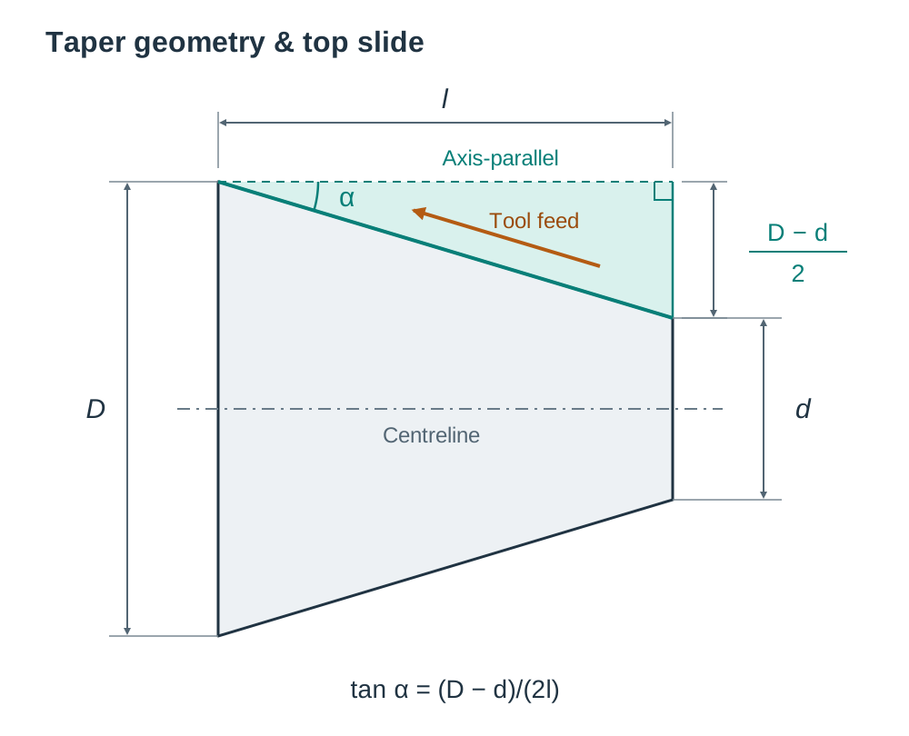
The top slide is swivelled to the half-angle (semi-angle) of the taper:
where is the major diameter, is the minor diameter, and is the length of the tapered section. The diameter difference is divided by because the tool cuts only on one side of the workpiece, creating the change in radius.
Tailstock Offset Calculation
When turning between centres, the tailstock body can be shifted off centre by an offset distance :
where is the overall length of the workpiece between centres, is the length of the tapered section, is the large diameter, and is the small diameter.
Screwcutting on the Lathe
Screwcutting links spindle rotation to carriage movement through a gearbox and leadscrew, moving the tool by an exact lead per revolution.
- Pitch: the distance between matching points on adjacent thread crests.
- Lead: the axial distance a nut advances in one complete revolution ().
- Multistart threads: have two or more separate continuous threads cut side by side. They allow rapid axial travel per revolution without deepening the thread groove, making them ideal for quick-acting vices, valve spindles, and bottle caps. On a lathe, the leadscrew gears are set to the lead. After cutting the first thread, the workpiece is indexed by (e.g. for a two-start thread) before cutting the next start.
- Left-hand threads: tighten when rotated anticlockwise. They are used on bicycle left pedals and flammable gas fittings. On the lathe, the leadscrew drive is reversed relative to the spindle using the tumbler gear, feeding the carriage from headstock toward tailstock while the spindle runs forward.
The Shaping Machine
A shaping machine produces flat horizontal, vertical, and angular surfaces using a single-point cutting tool that reciprocates in a straight line over stationary work held in a machine vice. The shaper is specified by its maximum length of stroke (for example, a shaper).
Construction and Cutting Action
- Ram: slides back and forth in horizontal bed guides, carrying the toolhead across the work.
- Cutting stroke: metal is cut only on the forward stroke.
- Clapper box: a hinged toolholder mounted on the toolhead. On the return stroke, the clapper box pivots upward slightly, allowing the tool to drag lightly over the work rather than digging in, protecting the cutting edge.
- Quick-return mechanism: a crank and slotted lever mechanism drives the ram. The crankpin sweeps through a large angle during the forward cutting stroke (slow forward movement) and a smaller angle during the return stroke (fast return). This saves time on the idle stroke.
- Feed motion: the worktable feeds automatically across by a set increment at the end of each return stroke (intermittent feed).
- Operations: flat horizontal surfacing, vertical slots, dovetails, keyways, and angular faces (by swivelling the toolhead).
Milling Operations, Upcut vs Downcut, and Indexing
Milling removes metal using a rotating multi-toothed cutter while the workpiece, secured to the machine table, feeds past it along three linear axes (, , and ). A milling machine is specified by its table working surface, axis travel lengths, spindle taper, and motor power.
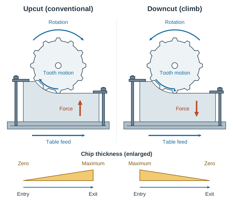
Upcut vs Downcut Milling
(What to draw: circular cutter with tooth rotation arrow, rectangular workpiece with table feed arrow, and the resulting wedge-shaped chip.)
| Operational Feature | Upcut (Conventional) Milling | Downcut (Climb) Milling |
|---|---|---|
| Cutter rotation | Rotates against the direction of table feed. | Rotates in the same direction as table feed. |
| Chip thickness | Starts at zero and increases to maximum thickness at tooth exit. | Starts at maximum thickness and tapers to zero at tooth exit. |
| Cutting forces | Lifts the workpiece upward off the table; pushes table back against the feed screw. | Pushes the workpiece down into the table; pulls table forward with the cut. |
| Clamping needs | Demands very rigid clamping to resist the lifting forces. | Requires less downward clamping force because cutting forces seat the work. |
| Machine safety | Safe on standard manual workshop mills; cutting forces take up leadscrew backlash. | Extremely dangerous on manual mills without a backlash eliminator; cutter grabs work and jams. Safe on CNC ballscrews. |
| Surface finish | Cutter rubs before biting into metal, causing slight work hardening and tool wear. | Cleaner shearing cut and reduced rubbing deliver a superior surface finish. |
Milling Cutters
- End mill: has peripheral teeth and end teeth that do not cross the centre axis. It machines external steps, shoulders, and open-ended slots, but cannot plunge straight down into solid metal.
- Slot drill: has two or three flutes with cutting edges bridging the central axis. It can plunge directly into solid metal like a drill and traverse sideways to cut closed keyways and pockets.
Simple Indexing with a Dividing Head
A dividing head rotates a workpiece through precise angular divisions. It contains a worm-and-wheel reduction gear: rotating the index crank 40 complete turns rotates the main spindle exactly once. To divide a circle into equal parts:
When this produces a mixed number, the fractional part is matched to an available hole circle on the index plate, and sector arms are set to count the holes without manual counting each time.
Cutting Mechanics, Power, Fluids & Precision Grinding
Chip Formation and Machinability
- Machinability: describes how easily a material can be cut. It is assessed by cutting tool life, surface finish obtained, cutting forces, power consumed, and chip formation. Free-cutting mild steel and brass have high machinability; stainless steel and titanium have low machinability.
- Continuous chips: long, unbroken ribbons produced when ductile metals (like mild steel and aluminium) are cut at high speeds with positive rake angles. In automated machining, they are hazardous because they can wrap around tooling, scratch finished surfaces, and injure operators. Chip breakers ground into or clamped on the tool face curl and fracture the chip into small, safe C-shaped segments.
- Discontinuous chips: small, fractured segments formed when machining brittle metals (such as cast iron and brass) which fracture along the shear zone ahead of the cutting edge.
- Built-up edge (BUE): under heavy cutting pressure and localised heat, microscopic metal layers weld themselves to the rake face near the tool tip. As this deposit grows, it alters the tool shape, blunts the cutting action, and eventually breaks away. Loose fragments stick to both the chip and the workpiece surface, causing a rough, torn finish and accelerating tool wear. BUE forms at low speeds without coolant; it is prevented by increasing cutting speed, using cutting fluids, and selecting tools with large positive rake angles or polished surfaces. (What to draw: tool tip, oncoming workpiece, exiting chip, and the triangular welded deposit sitting between the rake face and chip.)
Cutting Speeds and Spindle Speed Calculation
Spindle speed () in rev/min depends on the material's recommended surface cutting speed () in m/min and the workpiece or cutter diameter () in mm:
The factor of 1000 converts metres to millimetres.
Cutting Power
The power () consumed at the cutting tool in watts is given by:
where is the tangential cutting force in newtons (N) and is the cutting speed in metres per second (m/s).
Tool Life and Cutting Speed
As cutting speed rises, the cutting temperature increases and tool wear accelerates. Tool life falls steeply as cutting speed increases (described by Taylor's tool-life relationship, ). Cutting speeds are chosen to balance productivity against tool replacement costs. HSS tools are tough, cheap, and can be re-ground, but lose hardness at elevated temperatures. Tungsten carbide inserts withstand much higher temperatures and cutting speeds, but are brittle and are discarded or indexed rather than re-ground.
Cutting Fluids
Cutting fluids perform three vital tasks: cooling the tool and workpiece to retain tool hardness, lubricating the tool face to reduce friction and power draw, and flushing away swarf.
- Soluble oil: mineral oil mixed with water to form a milky emulsion. It provides excellent cooling with some lubrication for general turning and milling.
- Neat cutting oil: straight mineral oil with extreme-pressure additives. Used for high-friction, slow-speed cuts like threading and gear cutting.
- Synthetic fluids: chemical solutions in water providing clean cooling and high resistance to bacterial decay.
- Dry cutting: cast iron and brass are cut dry because liquid coolant mixes with powdery chips to form an abrasive sludge.
- Application methods: flood cooling (continuous low-pressure stream), mist spray, brush/drip, or through-tool coolant channels.
- Rancidity: caused by anaerobic bacteria thriving in stagnant, warm coolant. Prevented by regular aeration, filtering swarf, maintaining the correct oil-water concentration, skimming tramp oil, and adding bactericides.
Precision Grinding
Precision surface grinders finish hardened components to tolerances within . A surface grinder is specified by its magnetic chuck dimensions and maximum grinding height.
- Wheel composition: abrasive grains held by a bonding matrix. Aluminium oxide is tough and used on high-tensile steels. Silicon carbide is harder and sharper, used on cast iron, brass, and carbide tools.
- Abrasive: aluminium oxide or silicon carbide.
- Grain (grit) size: coarse grit for fast stock removal, fine grit for a smooth finish.
- Grade: how firmly the bond holds the grains. A hard grade holds them tightly and suits soft materials; a soft grade releases blunt grains easily and suits hard materials.
- Structure: the spacing of the grains, from open to dense. Open structure leaves room for chips.
- Bond: for example vitrified or resinoid.
- Wheel maintenance: truing restores the wheel's concentric circular shape and flat face using an industrial diamond tool. Dressing fractures glazed, blunt abrasive grains and clears metal chips embedded in the wheel face, exposing fresh, sharp cutting edges.
Metrology: Limits, Fits, Gauges & Precision Measurement
No part can be manufactured to an exact mathematical size. Metrology defines the allowable size variation so parts fit and work together correctly.
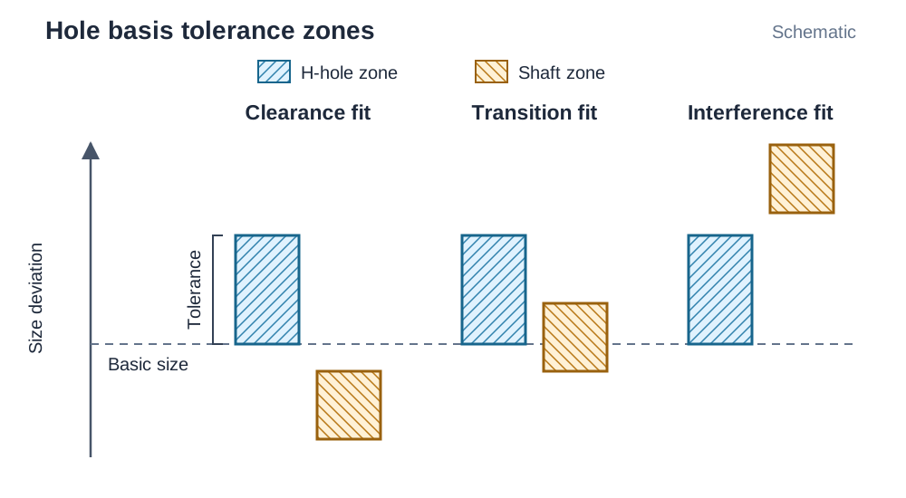
Limits and Fits Terminology
- Basic (nominal) size: the theoretical reference size from which limit dimensions are derived.
- Limits of size: the maximum (upper) and minimum (lower) permitted sizes of a feature.
- Tolerance: the total allowable variation on a dimension ().
- Allowance: the intentional difference between the maximum material dimensions of mating parts. It is the minimum clearance or maximum interference.
- Interchangeability: components are manufactured within specified limits so that any random part will assemble and function with any matching mating part without hand fitting.
- Selective assembly: parts are manufactured to wider, cheaper tolerances, measured, and sorted into graded size bins (e.g. small, medium, large). Matching bins are paired together (small shafts into small bores) to produce high-precision fits without the high cost of holding tiny individual tolerances. Used for ball bearings and engine pistons.
- Hole basis system: the standard system where the basic size is assigned to the hole and the hole's lower limit equals the basic size (an hole). The shaft tolerance zone is varied to produce clearance, transition, or interference fits. This is standard industrial practice because hole-producing tools (drills, reamers, broaches) have fixed diameters and are expensive to customise, whereas shaft diameters are easily turned or ground to any size on standard machines.
Classes of Fit
- Clearance fit: the hole is always larger than the shaft, leaving a running or sliding clearance.
- Interference fit: the shaft is always larger than the hole. Assembly requires hydraulic pressing or thermal expansion (shrink fitting), locking the parts rigidly together.
- Transition fit: the tolerance zones overlap. Depending on the random sizes produced, the assembly can result in either a light clearance or a light press fit.
Inspection with Limit Gauges & Taylor's Principle
- Plug gauges: inspect internal holes. The cylindrical GO end checks the maximum material condition (minimum hole size) across the full length of the bore. The NOT GO end checks the least material condition (maximum hole size) and must not enter.
- Snap (gap) gauges: inspect external shafts. The GO gap is set to the maximum shaft diameter and must slide over the work. The NOT GO gap is set to the minimum shaft diameter and must not pass over.
- Taylor's Principle: the GO gauge must inspect the feature at its maximum material condition across its full shape and length simultaneously. The NOT GO gauge must inspect only a single dimension at the least material condition.
Slip Gauges
Slip gauges are precision-lapped rectangular blocks of hardened steel or ceramic that serve as the physical standard of length in workshops. When two clean blocks are slid together with light pressure and a slight twist (wringing), molecular attraction holds them firmly without an air gap.
- Grades of accuracy: Calibration grade (used to inspect other gauges), Grade 00 (reference and standards rooms), Grade 0 (inspection departments), Grade 1 (toolroom setting), Grade 2 (workshop production).
Angular Measurement: Sine Bar, Rollers & Balls
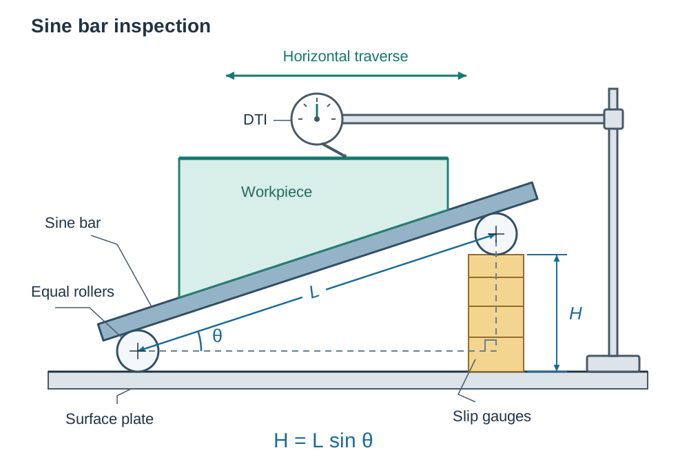
A sine bar has two precision cylindrical rollers of equal diameter set at an exact centre distance ( or ). When rested on a surface plate with one end supported on a wrung slip gauge stack of height , it forms a right-angled triangle:
To inspect an angle, the workpiece is seated on the tilted sine bar and a Dial Test Indicator (DTI) is traversed horizontally along its top face. If the DTI needle remains on zero throughout the traverse, the angle matches perfectly. If not, the difference in reading across the traverse reveals the angular error.
Precision rollers and balls: used with micrometers or vernier height gauges to check angles and tapers that cannot be reached directly. Two rollers of known diameter placed at two heights against an external taper allow the half-angle to be found from:
where and are micrometer readings over the rollers and is the difference in height created with slip gauges.
Screw Thread Measurement
- Screw pitch gauge: a fan of steel blades with precision-cut tooth profiles used to identify thread pitch by matching teeth against the thread.
- Thread form (centre) gauge: a flat profile gauge used to check the thread angle and align single-point screwcutting tools square to the work.
- Thread plug and ring gauges: GO and NOT GO limit gauges for checking internal and external screw threads.
- Profile projector (shadowgraph): shines parallel light past a component and projects an enlarged silhouette onto a calibrated screen, allowing thread pitch, root radii, and flank angles to be inspected without touching delicate parts.
Surface Finish Specification ()
Surface roughness is specified by the roughness average () in micrometres (), representing the arithmetical mean deviation of the profile from the centreline along a sampling length. It is measured with a diamond-tipped stylus profilometer traversing the surface.
CNC Machining, Control Systems & Automation
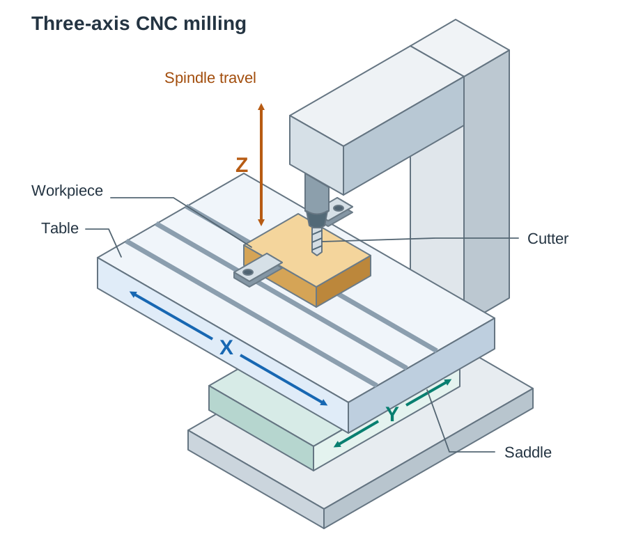
Computer Numerical Control (CNC) means a computer program controls machine movements. Alphanumeric G-codes command axis coordinates and speeds, while M-codes manage machine functions like spindle rotation and coolant supply. High-precision recirculating ballscrews eliminate mechanical backlash.
Coordinate Systems
- 3-axis CNC milling: coordinates control table longitudinal travel (), saddle cross travel (), and vertical spindle motion (). (What to draw: machine table with perpendicular X and Y arrows, and vertical Z arrow aligned with the spindle axis.)
- 2-axis CNC turning: controls carriage travel along the spindle axis () and cross-slide movement controlling part diameter ().
CNC Terms Asked in Examinations
- Machine tool envelope: the maximum physical working space reachable by the cutting tool along the machine's , , and axes. The workpiece, fixtures, and tool travel paths must stay entirely inside this envelope.
- Open-loop control: the controller sends pulse signals to stepper motors but receives no positional feedback. If a step is missed under heavy load, the machine loses position without detecting the error. Used on budget and educational machines.
- Closed-loop control: rotary encoders or linear scales continuously measure the actual position and speed of the axis slides and feed the data back to the controller. The controller compares actual position with target position and corrects errors immediately, ensuring high precision.
- Tool offsets: stored numerical values in the CNC controller defining the length and tip radius of each cutter. The controller offsets axis coordinates automatically, so programmers do not need to rewrite programs when tools are replaced.
- Automatic tool changer (ATC): a revolving magazine or drum that swaps cutters in the spindle within seconds without operator intervention, enabling multi-operation machining.
- Software simulation: running the G-code program virtually on a computer display to verify toolpaths, check cycle times, and detect clamp collisions before cutting metal.
- Dry run (test run): running the program on the actual CNC machine without a workpiece or above the part with coolant off, checking machine clearances and movements safely.
Choosing CNC vs Manual Machining
- Choose CNC for: high-volume batch production (e.g. plumbing fittings), intricate 3D contoured surfaces, and components requiring close tolerances with guaranteed repeatability.
- Choose manual machining for: one-off bespoke pieces (e.g. hand-turned chess pieces), simple short jobs where CNC programming and setup time would exceed machining time, and custom vehicle repair work (e.g. repairing a single damaged alloy wheel).
- Productivity and reliability: CNC delivers high productivity through continuous unmanned running, optimised cutting speeds, and fast tool changes. It provides high reliability because every component is produced identically from the verified program, eliminating human fatigue and operator error.
Key terms
- Rake Angle
- The angle on the cutting face of a tool that directs chip flow away from the cutting zone and controls shearing force.
- Clearance Angle
- The relief angle ground behind the cutting edge to prevent the tool flank from rubbing against the workpiece.
- Built-Up Edge (BUE)
- An accumulation of workpiece material that pressure-welds onto the tool rake face during cutting, degrading surface finish and accelerating tool wear.
- Continuous Chip
- A long, unbroken ribbon of metal produced when machining ductile materials at high cutting speeds.
- Discontinuous Chip
- Small, fractured chips formed when machining brittle metals such as cast iron or brass.
- Upcut Milling
- A milling operation where the cutter teeth rotate against the feed direction of the workpiece, creating an upward lifting force.
- Downcut Milling
- A milling operation where the cutter teeth rotate in the same direction as table feed, pushing the workpiece down into the table.
- Dividing Head
- A work-holding device featuring an internal 40:1 worm-and-wheel reduction gear used to index work through precise angles on a milling machine.
- Tolerance
- The total allowable variation on a dimension, calculated as the upper limit minus the lower limit.
- Hole Basis System
- A system of limits and fits where the hole size is kept constant at the basic size and shaft limits are varied to achieve the required fit.
- Taylor's Principle
- The metrology rule stating that a GO gauge must inspect maximum material conditions across all dimensions simultaneously, whereas a NOT GO gauge checks a single dimension at least material condition.
- Sine Bar
- A hardened steel measuring bar with two precision rollers set at an exact centre distance, used with slip gauges and trigonometry to inspect angles.
- Slip Gauges
- Precision-lapped rectangular blocks of hardened steel or ceramic that act as the physical standard of length in engineering workshops.
- Machine Tool Envelope
- The maximum working volume defined by the total physical travel limits of a CNC machine's linear axes.
- Tool Offset
- A stored numerical value in a CNC controller that compensates for the length and diameter of a cutting tool.
- Selective Assembly
- A manufacturing method where parts made to wider tolerances are sorted into size groups and matched to produce high-precision fits economically.
Check yourself
What defect is left on the end face of a workpiece during facing if the lathe tool is set off centre?
An uncut central pip remains on the face because the cutting edge sits above or below the rotational axis.
A hole is dimensioned 20 +0.021 / +0.000 mm and a shaft is dimensioned 20 +0.035 / +0.022 mm. What class of fit is produced?
Interference fit. The maximum clearance is 20.021 - 20.022 = -0.001 mm and the minimum clearance is 20.000 - 20.035 = -0.035 mm. Since both values are negative, the shaft is always larger than the hole.
How many turns of the index crank are required to machine 30 divisions using an index plate with hole circles 15, 16, 17, 18, 19, 20?
40 / 30 = 1 1/3 turns, which equals 1 full turn plus 5 holes on the 15-hole circle (or 1 full turn plus 6 holes on the 18-hole circle).
Why is the clapper box on a shaping machine hinged?
To allow the tool to lift freely on the return stroke and drag lightly over the work rather than digging in, protecting the cutting edge.
What is the difference between open-loop and closed-loop CNC control?
Open-loop sends signals to motors without feedback, meaning missed steps cannot be detected. Closed-loop uses encoders to feed actual positions back to the controller, correcting positional errors continuously.