
An oblique plane is a flat surface inclined to both principal planes of reference: the Horizontal Plane (HP) and the Vertical Plane (VP). Because it slopes in two directions at once, it never presents an edge view in standard plan or elevation. In Leaving Certificate Design and Communication Graphics at Higher Level, descriptive geometry of lines and planes carries substantial marks across the written paper. The techniques examined are: finding the traces of a plane; locating points on the plane with level lines and frontal lines; projecting an auxiliary edge view to find true inclinations; rebating the plane to find true shapes and the true angle between traces; sectioning right and tapering solids; constructing planes from given inclinations via the cone and sphere methods; and setting up containing planes to solve skew-line problems.
Anatomy of an Oblique Plane: Traces and Reference Planes
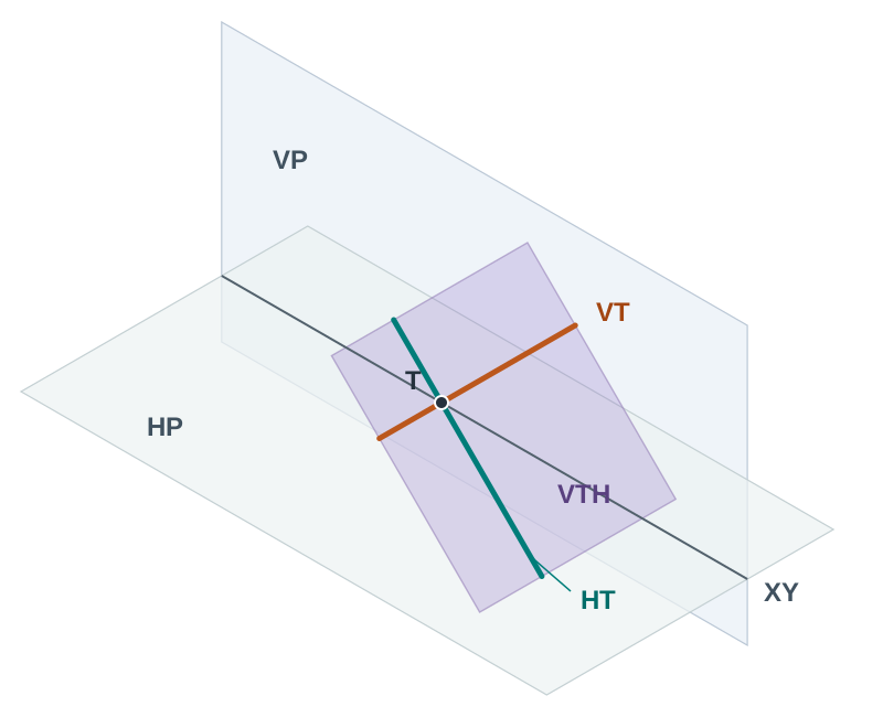
In orthographic projection, three-dimensional space is organised around the Horizontal Plane (HP) and the Vertical Plane (VP), which intersect along the ground line (XY).
A simply inclined plane is perpendicular to one reference plane and tilted toward the other. Looking directly along its line of perpendicularity reveals the surface as an edge view (a single straight line), allowing you to measure its inclination directly from standard views.
An oblique plane is inclined to both the HP and the VP simultaneously. It never appears as an edge in standard plan or elevation, meaning every true dimension, angle, and shape must be established through geometric construction.
| Plane Type | Relation to HP and VP | Edge View in Standard Views? | Determining True Angles |
|---|---|---|---|
| Simply Inclined | Perpendicular to one, inclined to the other | Yes (in plan or elevation) | Measured directly from the edge view |
| Oblique | Inclined to both HP and VP | No | Requires an auxiliary edge view or rebatement |
Because planes extend infinitely in space, an oblique plane is defined on paper by its intersections with the reference planes. These lines of intersection are called traces:
- Vertical Trace (VT): The line where the oblique plane intersects the VP. It is drawn in elevation, and its plan view lies directly on the XY line.
- Horizontal Trace (HT): The line where the oblique plane intersects the HP. It is drawn in plan, and its elevation view lies directly on the XY line.
The point where the HT and VT meet on the XY line is the vertex of the traces (labelled T). The plane is referenced as plane VTH. Because the XY line belongs to both reference planes, any point where the oblique plane cuts the XY line must belong to both traces at once.
How to Recognise the Question Direction
- If the question provides the VT and HT, you are asked to put something onto the plane: complete an elevation, cut a solid, draw an inscribed figure, or determine an inclination.
- If the question provides a physical surface or coordinates and asks for plane VTH, you are asked to take traces off the plane by extending lines on the surface until they pierce the HP and VP.
Lines and Points on an Oblique Plane
A point lies on an oblique plane if and only if it sits on a straight line that lies entirely within that plane. Two families of lines are used to project points between plan and elevation without drawing auxiliary views.
Level Lines (Horizontal Lines on a Plane)
A level line lies on the oblique plane at a constant height above the HP:
- In elevation, it runs parallel to the XY line.
- In plan, it runs parallel to the Horizontal Trace (HT).
- Because it is parallel to the HP, its plan projection shows its true length.
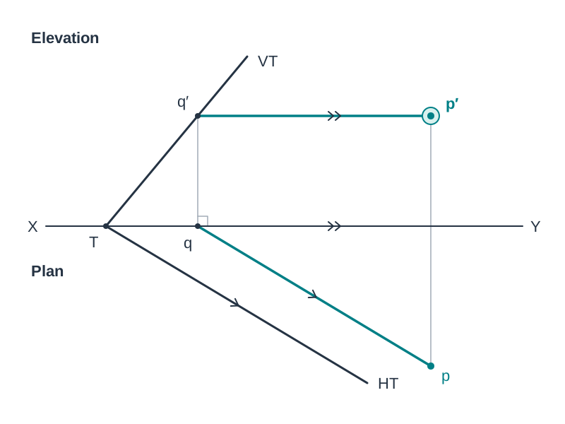
To find the elevation of a known plan point p on plane VTH:
- Through plan point p, draw a straight line parallel to the HT until it intersects the XY line at point q.
- From q, erect a vertical projector perpendicular to XY to strike the Vertical Trace (VT) at point q'.
- Through q', draw a horizontal line in elevation parallel to the XY line.
- Project the original point p vertically upwards from plan. Where this projector intersects the horizontal line from q' defines the exact elevation point p'.
Frontal Lines
A frontal line lies on the oblique plane at a constant distance in front of the VP:
- In plan, it runs parallel to the XY line.
- In elevation, it runs parallel to the Vertical Trace (VT).
- Its elevation projection displays its true length.
Line of Greatest Slope
The line of greatest slope represents the steepest path down the oblique plane to the HP. In plan, it is always perpendicular to the HT. Its true inclination to the ground equals the true inclination of the plane itself.
Plotting Laminae and Finding Traces
A lamina is a flat surface treated as having negligible thickness, defined by spatial vertices or coordinates.
Plotting a Lamina from Co-ordinates
Points are typically specified in Leaving Certificate examinations as three figures: (distance measured along the XY line from an origin on the left, distance in front of the VP, height above the HP).
- For a point A (30, 20, 45): in plan, measure 30 mm along XY, then 20 mm below XY (in front of VP) to locate a. In elevation, measure 30 mm along XY, then 45 mm above XY to locate a'. Points a and a' must sit on the same vertical projector.
- Plot all vertices and connect corresponding points to establish the lamina in plan and elevation.
Finding Plane Traces from a Given Lamina (e.g. Triangle ABC)
- Establish a level line: In elevation, draw a horizontal line from vertex a' parallel to XY across the lamina to intersect edge b'c' at d'. Project d' vertically down to plan edge bc to establish line ad. Because ad is a level line on the plane, the Horizontal Trace (HT) must run parallel to ad.
- Locate an HT piercing point: Extend any suitable edge in elevation (such as c'a') until it strikes XY at h'. Project h' vertically down into plan to intersect the continuation of edge ca at H₁. Point H₁ lies on the HP and therefore on the HT.
- Draw the HT: Through H₁, draw a straight line parallel to ad. Extend this line until it crosses the XY line at vertex T.
- Locate a VT piercing point: Extend an edge in plan (such as ab) until it strikes XY at v. Project v vertically up into elevation to intersect the continuation of line a'b' at V₁.
- Draw the VT: Connect vertex T on the XY line through point V₁ with a firm straight line.
Self-Check: The VT must pass cleanly through both T and V₁. If it does not, one of your line extensions or vertical projections is inaccurate.
True Inclinations to the Principal Planes
The angles that traces make with the XY line on paper are apparent angles, not the true angles of the plane. True inclinations must be measured in a view where the plane appears as an edge.
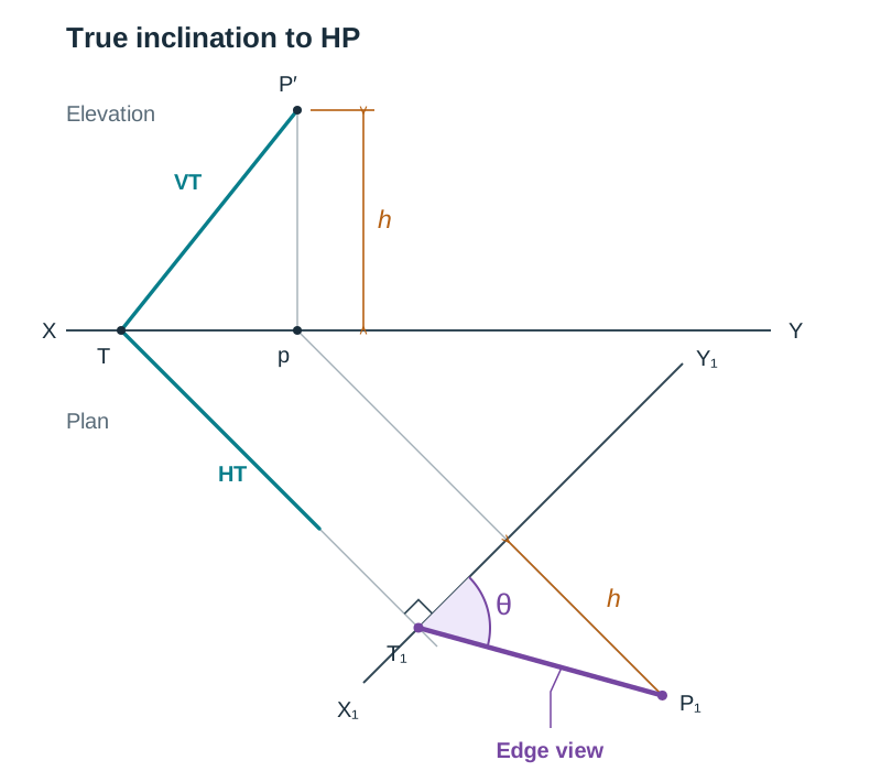
True Inclination to the Horizontal Plane (θ)
- Set up an auxiliary ground line X₁Y₁ perpendicular to the Horizontal Trace (HT) in plan.
- Project all points parallel to the HT across X₁Y₁ (looking along the HT reduces it to a single point T₁ on X₁Y₁).
- Pick any point P on the VT in elevation, measure its vertical height h above the XY line, and transfer that height h perpendicular to X₁Y₁ along its projector.
- Join T₁ to this projected point. This straight line represents the plane seen as an edge view.
- Measure the acute angle between the edge view and X₁Y₁. This is the true inclination (θ) to the HP.
True Inclination to the Vertical Plane (φ)
- Set up an auxiliary ground line X₁Y₁ perpendicular to the Vertical Trace (VT) in elevation.
- Project points parallel to the VT across X₁Y₁.
- Transfer plan depths (distances below the original XY line) perpendicular to X₁Y₁.
- Connect the points to form the edge view. The acute angle between this edge view and X₁Y₁ gives the true inclination (φ) to the VP.
Boundary Check
For any oblique plane, the sum of its true inclinations must satisfy:
If θ + φ ≤ 90°, the plane cannot exist as an oblique plane.
True Shapes and True Angle Between Traces via Rebatement
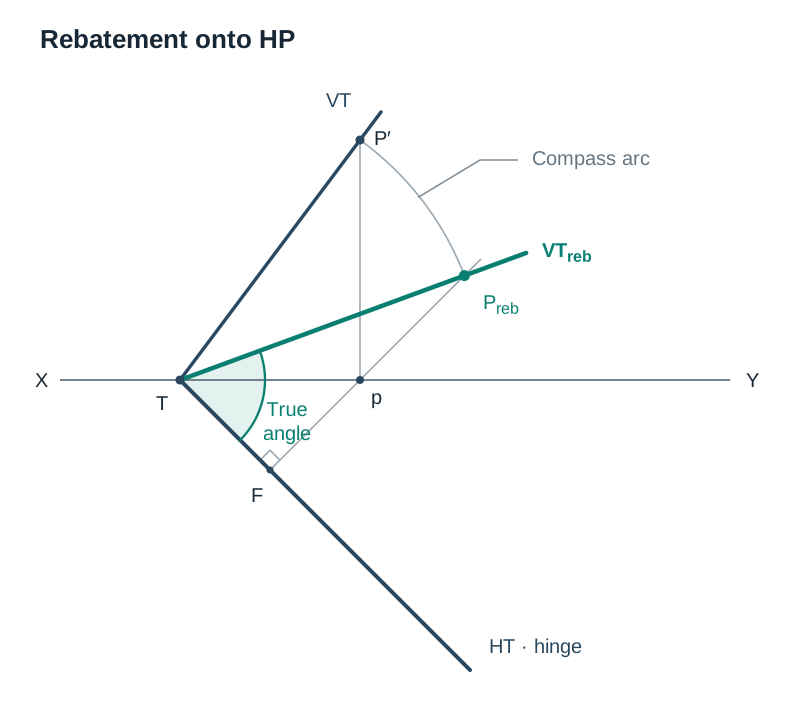
Rebatement is the geometric rotation of an oblique plane about one of its traces until it lies flat against a principal reference plane. Once flattened, all surface features, angles, and shapes appear undistorted.
True Angle Between Traces (VT and HT)
- Choose the HT as the stationary hinge line on the HP.
- Pick a convenient point P' on the VT at height h in elevation, and drop a vertical projector to find its plan position p on the XY line.
- In plan, draw a line from p perpendicular to the HT. This represents the circular path point P follows as it swings down onto the HP.
- Centre your compass at vertex T on the XY line. Set the compass radius to the distance from T to P' measured directly along the VT in elevation (TP' is a true length because P' lies directly on the VP).
- Swing an arc of radius TP' from T to intersect the perpendicular line from p at point P_reb.
- Draw a firm line from T through P_reb. This is the rebated vertical trace (VT_reb).
- The angle between the stationary HT and VT_reb is the true angle between the traces.
True Shape of an Oblique Lamina by Rebatement
For each vertex A of the lamina:
- Drop a perpendicular from the plan point a to the HT and call the foot of the perpendicular F.
- Measure the distance Fa in plan and the vertical height h of vertex a' above the XY line in elevation.
- The rebated vertex A₁ lies on the extension of that same perpendicular line, on the same side of the HT as a, at a distance from F equal to:
- Repeat for every vertex and join them in sequence. The resulting figure is the undistorted true shape of the lamina.
Alternatively, obtain an auxiliary edge view (X₁Y₁ perpendicular to HT), then project a second auxiliary view with X₂Y₂ parallel to the edge view, transferring distances from plan.
Lines of Intersection, Dihedral Angles, and Piercing Points
Descriptive geometry frequently requires analysing how planes and lines interact in three dimensions.
Line of Intersection of Two Oblique Planes
Two non-parallel planes intersect in a single straight line. Use the reference planes as common ground:
- The horizontal traces HT₁ and HT₂ both lie on the HP. Where they cross in plan is a mutual point P. Its elevation p' lies on the XY line.
- The vertical traces VT₁ and VT₂ both lie on the VP. Where they cross in elevation is a second mutual point Q. Its plan q lies on the XY line.
- Join p to q in plan and p' to q' in elevation. Line PQ is the line of intersection.
If traces cross off the page: Draw a horizontal cutting plane at a selected height h. It cuts each oblique plane in a level line parallel to that plane's HT. Where the two level lines cross in plan is a point on the line of intersection at height h. Repeat at a second height and connect the two resulting points.
Dihedral Angle Between Two Planes
The dihedral angle is the true angle between two intersecting planes, measured perpendicular to their line of intersection. It requires two consecutive auxiliary views:
- Find the line of intersection between the two planes.
- First auxiliary: Draw X₁Y₁ parallel to the plan of the line of intersection. Project both planes into this view. The line of intersection now appears in true length.
- Second auxiliary: Draw X₂Y₂ perpendicular to that true length line. Transfer distances from the plan view (the view prior to the first auxiliary). The line of intersection collapses to a point, and each plane appears as a straight line radiating from it.
- The angle between these two lines is the dihedral angle. Dimension it with an arc and label its value.
Piercing Point of a Line and an Oblique Plane
To find where a spatial line AB pierces an oblique plane VTH:
- Contain line AB in a vertical cutting plane whose plan trace coincides with line ab.
- Find where this vertical cutting plane cuts plane VTH: line ab crosses the HT at point 1 in plan (height zero on XY in elevation) and crosses the XY line at point 2 (projected up to the VT in elevation). Join 1' and 2' in elevation.
- Where line 1'2' intersects line a'b' in elevation is the piercing point p'. Project p' down to ab in plan to locate p.
- Any part of the line hidden below or behind the plane is drawn using dashed lines.
Shortest Distance from a Point to a Plane: In an auxiliary edge view of the plane (X₁Y₁ perpendicular to HT), project the point into the same view. Measure the perpendicular distance from the point to the edge line.
Solids Cut by an Oblique Plane and Curves on a Plane
When an oblique cutting plane slices through a solid, the method depends on whether the solid's edges are vertical or tapering.
Vertical Solids (Prisms and Cylinders)
In a prism or cylinder standing on the HP, all upright edges appear as points in plan. Therefore, the plan of the cut surface is already known, and only the heights in elevation must be found:
- For each corner point in plan, construct a level line parallel to the HT to meet the XY line.
- Project vertically up to the VT, then carry a horizontal line across in elevation.
- Project the plan point vertically up to meet this horizontal line in elevation.
- For a cylinder, divide the circular plan into 12 equal increments using 30°/60° lines, locate the elevation of each generator using level lines, and connect the plotted points with a smooth curve.
Tapering Solids (Pyramids and Cones)
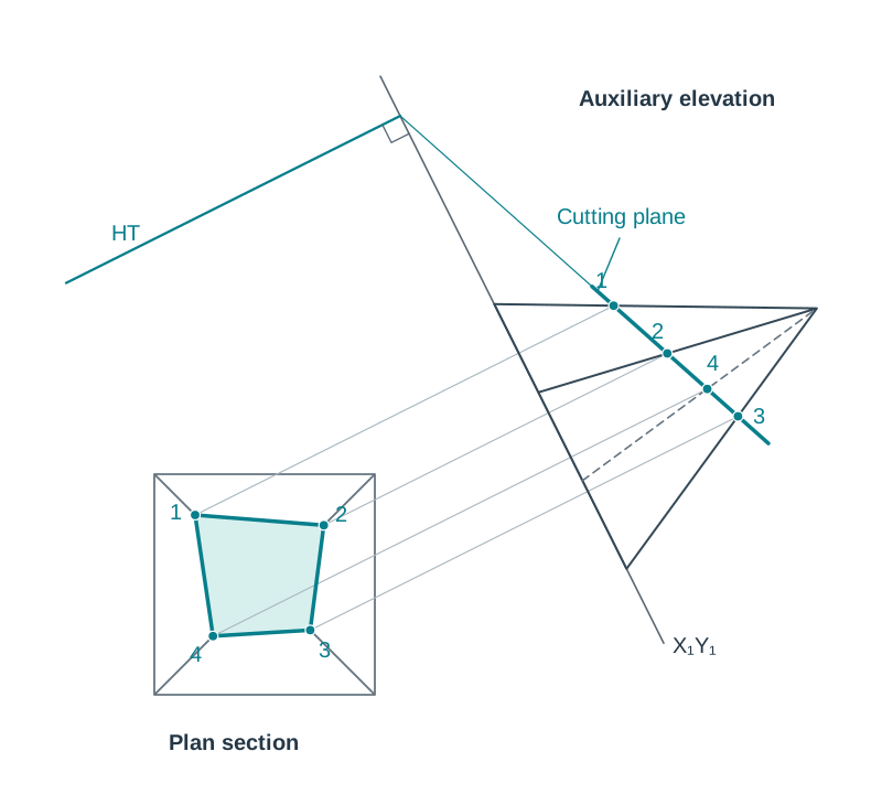
In a pyramid or cone, the edges slope, meaning both the plan and elevation positions of the cut points are unknown. Use the Auxiliary Edge View Method:
- Set up an auxiliary elevation with X₁Y₁ perpendicular to the HT.
- Project the solid into the auxiliary view by transferring heights from elevation.
- Project the cutting plane into the auxiliary view, where it appears as a straight edge line.
- Mark where this edge line crosses the solid's sloping edges.
- Project these cut points back perpendicular to X₁Y₁ onto the corresponding edges in plan.
- Project the points from plan vertically up to their respective edges in elevation, and connect them in sequence.
True Shape of the Cut Section
- From the auxiliary view showing the cutting plane as an edge, set up a second auxiliary view with X₂Y₂ parallel to the edge line.
- Project all cut points perpendicular to X₂Y₂.
- Measure the distance of each cut point from X₁Y₁ in the plan view, and transfer this distance from X₂Y₂ along its projector.
- Join the points to reveal the true shape of the section.
A Circle Lying on an Oblique Plane
A circle resting on an oblique plane projects as an ellipse in both plan and elevation:
- In an auxiliary view showing the plane as an edge (or rebated flat), draw the circle in its undistorted circular true shape.
- Divide the circle into 12 equal parts.
- Project each point back to the edge view, then perpendicular into plan (transferring plan distances), and finally vertically up to elevation using level lines.
- Connect the plotted points with a smooth freehand-quality curve.
Constructing Planes: Cone Method, Sphere Method, and Tangent Planes
At Higher Level, you must be able to establish the traces of an oblique plane given specific geometric constraints.
1. Plane Containing a Line and Inclined at Angle θ to the HP (Cone Method)
A right cone standing on its base on the HP with base angles equal to θ has all its generators inclined at θ to the HP. Any plane tangent to this cone will also be inclined at angle θ to the HP.
- Find the horizontal piercing point H (plan h₁, elevation on XY) and the vertical piercing point V (elevation v', plan on XY) of the given line.
- Choose a point A on the line at a convenient height h_A above the HP; A is the apex of a right cone standing on the HP.
- Calculate the cone base radius: $$
- In plan, draw a circle of radius r centred on a.
- From horizontal piercing point h₁, draw a tangent to this circle; that tangent is the Horizontal Trace (HT). Note: Two tangents can be drawn from h₁, meaning two valid planes satisfy the condition. If h₁ falls inside the circle, no solution exists because the given line is steeper than the required inclination.
- Extend the HT to meet the XY line at vertex T. Draw the Vertical Trace (VT) from vertex T through vertical piercing point v' in elevation (since V lies on the VP).
2. Tangent Planes to Curved Surfaces
A tangent plane touches a curved surface at one point (sphere) or along one straight generator (cone/cylinder):
- Tangent to a sphere at point P: The tangent plane is perpendicular to radius CP. Project an auxiliary view showing CP in true length; the tangent plane appears as an edge perpendicular to CP through P.
- Tangent to a cone along a generator: The plane contains that generator and the tangent to the base circle at the generator's base point. In plan, this base tangent gives the direction of the HT.
3. Plane Inclined at θ to the HP and φ to the VP (Sphere Method)
- Draw a sphere of arbitrary radius R centred at point c on the XY line.
- In elevation, draw tangents to the sphere at angle θ to XY, defining a cone on the HP with plan base radius $$
- In plan, draw tangents to the sphere at angle φ to XY, defining a cone against the VP with elevation base radius $$
- Draw the HT tangent to the plan base circle and the VT tangent to the elevation base circle, ensuring both traces intersect at a mutual point T on the XY line.
Skew Lines: The Containing Plane Method
Skew lines are straight lines in three-dimensional space that are neither parallel nor intersecting. They do not lie in the same plane.
To determine the shortest perpendicular distance, shortest horizontal distance, or shortest vertical distance between two skew lines AB and CD, construct an oblique plane containing line AB and parallel to line CD:
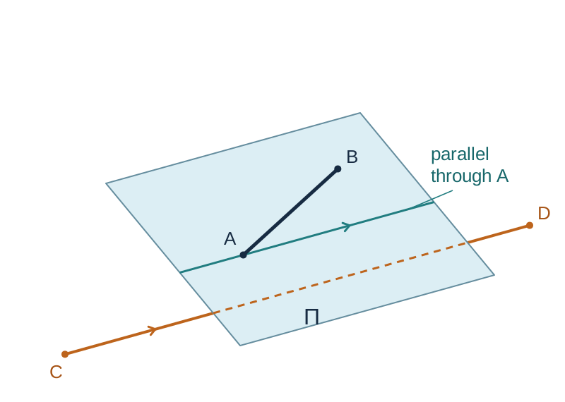
- Through a' in elevation, draw a line parallel to c'd'. Through a in plan, draw a line parallel to cd.
- Line AB and this newly drawn line define a plane that contains AB and is parallel to CD.
- Establish a level line on this plane (horizontal in elevation, projected to plan) to determine the direction of the plane's horizontal trace.
- Set up an auxiliary ground line X₁Y₁ perpendicular to this level line. In this auxiliary view, the plane (and therefore line AB) appears as an edge view, and line CD projects as a straight line parallel to it.
- Shortest perpendicular distance: Measure perpendicular from the edge line of AB to line CD. This is the true shortest distance between the skew lines.
- Shortest horizontal distance: In this same auxiliary view, measure parallel to X₁Y₁ between the edge line and CD.
- Shortest vertical distance: In this same auxiliary view, measure perpendicular to X₁Y₁ (vertically) between the edge line and CD.
- Project the endpoints of the required distance connector back to the plan and elevation views.
Key terms
- Oblique Plane
- A flat plane inclined to both the Horizontal Plane (HP) and the Vertical Plane (VP), lacking perpendicularity to either reference plane.
- Vertical Trace (VT)
- The straight line formed by the intersection of an oblique plane with the Vertical Plane; drawn in elevation.
- Horizontal Trace (HT)
- The straight line formed by the intersection of an oblique plane with the Horizontal Plane; drawn in plan.
- Level Line
- A line on an oblique plane parallel to the HP; its elevation runs parallel to the XY line and its plan runs parallel to the HT, showing true length in plan.
- Frontal Line
- A line on an oblique plane parallel to the VP; its plan runs parallel to the XY line and its elevation runs parallel to the VT, showing true length in elevation.
- Line of Greatest Slope
- The steepest line lying on an oblique plane relative to the HP; in plan, it is perpendicular to the HT.
- Edge View
- An auxiliary projection viewed parallel to a line of true length on a plane, causing the entire plane surface to collapse into a single straight line.
- Rebatement
- The geometric operation of revolving an oblique plane about one of its traces until it lies flat on a principal reference plane, revealing true shapes and angles.
- True Inclination
- The real angle between the plane and a principal plane of reference (θ to the HP, φ to the VP), measurable only in a view where the plane appears as an edge.
- Dihedral Angle
- The true angle between two intersecting planes, measured perpendicular to their common line of intersection.
- Piercing Point
- The exact spatial point where a straight line passes through a plane surface.
- Skew Lines
- Non-coplanar lines in three-dimensional space that are neither parallel nor intersecting.
- Lamina
- A thin, flat planar surface treated as having negligible thickness, defined by spatial vertices or coordinates.
Check yourself
Where do the plan view of the VT and the elevation view of the HT lie?
Both lie directly along the XY line, because points on the VT have zero distance from the VP and points on the HT have zero height above the HP.
An oblique plane has a true inclination of 70° to the HP. Could its true inclination to the VP be 15°?
No. For any valid oblique plane, the sum of true inclinations must satisfy 90° < θ + φ < 180°. Here 70° + 15° = 85°, which is less than 90°, so the geometry is impossible.
You complete the elevation of a surface lying on plane VTH, but one corner plots below the XY line. What error has occurred?
The level line in plan was drawn parallel to the wrong line (such as the VT instead of the HT), or the vertical projector was carried to the wrong side of the reference plane.
Why does a level line on an oblique plane show its true length in plan view?
Because a level line maintains a constant height above the HP, making it parallel to the horizontal plane of projection.
In rebatement about the HT, what geometric line acts as the stationary axis of rotation?
The Horizontal Trace (HT) acts as the stationary hinge axis.
How do you align the auxiliary ground line X1Y1 to find the true inclination of an oblique plane to the Horizontal Plane?
Draw the X1Y1 line perpendicular to the Horizontal Trace (HT) in plan, projecting parallel to the HT.