
Axonometric projection is an orthogonal pictorial drawing system that shows all three dimensions of an object in a single view. By tilting the object and its three reference planes so that none are parallel to the picture plane, width, depth, and height appear together on one sheet. By the end of this topic you should be able to: set up the axonometric axes and the triangle of traces; rebat the reference planes to draw the given views true size; project those views into a finished isometric, dimetric, or trimetric picture; plot curves and spheres accurately; find the traces of a cutting plane; and work backwards from the pictorial view to recover a true plan or elevation.
Principles of Orthogonal Axonometric Projection
To understand axonometric projection, picture the inside corner of an open box where three mutually perpendicular planes meet at an origin :
- The Horizontal Plane (HP) forms the floor, containing the and axes.
- The Vertical Plane (VP) forms the back wall, containing the and axes.
- The End Vertical Plane (EVP) forms the side wall, containing the and axes.
In standard orthographic projection, you look square-on at one plane at a time. In orthogonal axonometric projection, the whole three-plane corner is tilted and viewed from an angle. Every projection ray stays parallel to the line of sight and strikes a single projection plane—the axonometric plane—at an angle of .
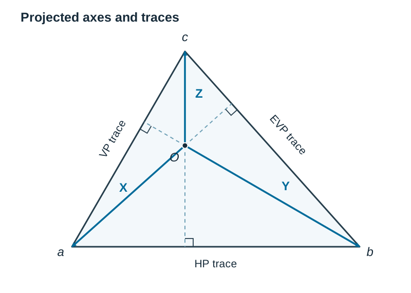
When this inclined plane cuts through the three reference planes, it leaves three intersection lines. Together, these lines form an acute-angled triangle known as the triangle of traces (labelled triangle ):
- Trace lies on the Horizontal Plane.
- Trace lies on the Vertical Plane.
- Trace lies on the End Vertical Plane.
Because the projection rays strike the axonometric plane at , two geometric theorems govern every drawing:
- Perpendicularity of axes: The projection of each coordinate axis from origin is strictly perpendicular to the opposite trace of the axonometric triangle. The projected -axis is perpendicular to trace , the projected -axis is perpendicular to trace , and the projected -axis is perpendicular to trace .
- The orthocentre: The projected origin is always the orthocentre of triangle , which is the unique point where its three altitudes intersect.
Because the axes slope away from the axonometric plane, lengths measured along them appear foreshortened. The steeper the angle an axis makes with the plane, the shorter its projected length becomes.
Classifying Projections: Isometric, Dimetric, and Trimetric
The tilt of the coordinate axes relative to the axonometric plane sets the projection type. Changing this tilt alters the angles between the projected axes on your page and changes the shape of the triangle of traces.
| Projection Type | Axis Inclinations to Axonometric Plane | Angles Between Projected Axes | Triangle of Traces () | Scale Factors |
|---|---|---|---|---|
| Isometric | All 3 axes equally inclined () | All 3 angles equal () | Equilateral (all sides equal) | Identical on all 3 axes (factor ) |
| Dimetric | 2 axes equally inclined, 1 different | 2 angles equal (e.g. ) | Isosceles (two sides equal) | 2 axes share the same factor; 1 differs |
| Trimetric | All 3 axes at different inclinations | All 3 angles unequal (e.g. ) | Scalene (all sides unequal) | 3 distinct scale factors across |
To check whether a given set of axes is valid for orthogonal axonometric projection:
- The three angles between the projected axes must sum to exactly .
- Every individual angle must be strictly obtuse (greater than and less than ). If an angle were , the triangle of traces would become a right-angled triangle, its orthocentre would fall onto a vertex, and one axis would project to zero length—giving an orthographic view rather than a 3D pictorial view.
Dimetric projection is used when you want to highlight one particular face, such as an entrance facade. Trimetric projection gives the most natural pictorial view because it eliminates distracting visual symmetry. Both are constructed using the exact same axes method.
The Isometric Scale and Drawing Circles
In introductory graphics, an isometric drawing is drawn using full, unscaled measurements along axes. That is quick and clear, but it is not a true projection; it produces an image roughly larger than life.
A true isometric projection represents the object tilted so that its body diagonal is perpendicular to the projection plane. In that position, each axis makes an angle of with the axonometric plane, creating natural foreshortening.
Deriving the Scale Factor
Picture a cube viewed along its diagonal. The horizontal diagonal of its top face remains parallel to the axonometric plane, so it stays true length :
- On the real square face, the edges make with that diagonal.
- In the projected isometric view, the face projects as a rhombus whose edges make with that same horizontal line.
Equating the shared horizontal half-diagonal length gives:
Every true dimension must be scaled by approximately to get its true isometric projection length.
Constructing the Scale on Paper
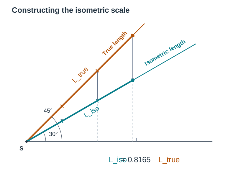
- Draw a horizontal baseline starting from a point .
- From , draw two rays: one at (the isometric scale line) and one at (the true length line).
- Step off true millimetre units along the line from .
- From each true mark on the line, drop a line vertically downward (perpendicular to the baseline) to intersect the ray.
- The distances intercepted along the line give the foreshortened isometric lengths.
Drawing Circles on Isometric Faces
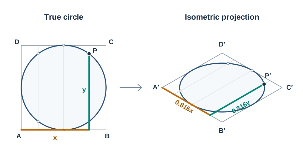
A circle on any isometric plane projects as an ellipse.
- Ordinate method (always accurate): Draw the true circle inside an enclosing square and cross it with ordinates. Draw the square as a rhombus (using isometric-scale lengths for a true projection, or full lengths for an isometric drawing). Step the ordinate spacings along the rhombus edges and plot the heights parallel to the adjacent axis, then join with a smooth curve.
- Four-centre approximation (isometric only): Draw the rhombus. From each obtuse () corner, draw lines to the midpoints of the opposite sides; these intersect at two centres on the long diagonal. Swing two large arcs from the obtuse corners and two small arcs from the internal intersection points. This works only for a rhombus; for dimetric and trimetric views, ordinates must be plotted.
The Axonometric Axes Method and Rebatment
What you are really doing with the axes method is drawing the object's plan on the tilted floor and its elevation on the tilted back wall, then projecting the whole assembly straight onto the page. The rebatment is the geometric trick that lets you hinge those tilted planes flat to draw the views true size first.
Sheet Layout
Place the triangle of traces near the centre of your drawing space. The rebatted plan sits on the far side of trace from origin , the rebatted elevation sits on the far side of trace , and the rebatted end view sits on the far side of trace . The finished pictorial drawing develops back towards the centre, around . Choose vertex along the -axis so the triangle leaves enough room for both the rebatted views and the central picture.
Setup Steps
- Draw the projected axes and meeting at at the angles specified in the question (usually with vertical).
- Pick a convenient position for vertex on axis . Through , construct a line perpendicular to axis to find vertex on axis . Through , construct a line perpendicular to axis to find vertex on axis . Connect . Check that line is strictly perpendicular to axis ; triangle is your triangle of traces.
Rebatting the Principal Planes
Whichever two views the question supplies determine which two reference planes you rebat:
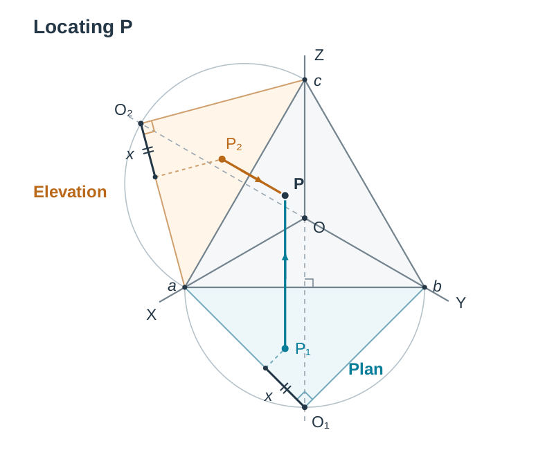
- Rebatting the Horizontal Plane (Plan): Bisect trace and draw a semicircle on as diameter on the side away from . Extend the projected -axis through and past trace until it intersects the semicircle at rebatted origin . Connect (true -axis) and (true -axis). By Thales' theorem, the angle is guaranteed to be .
- Rebatting the Vertical Plane (Elevation): Bisect trace and draw a semicircle on as diameter away from . Extend the projected -axis through and past trace to cut the semicircle at rebatted origin . Connect (true -axis) and (true -axis).
- Rebatting the End Vertical Plane (End View): Bisect trace and draw a semicircle on as diameter away from . Extend the projected -axis through and past trace to cut the semicircle at rebatted origin . Connect (true -axis) and (true -axis).
| View given | Plane | Hinge trace | Rebatted origin | Project points into axonometric view |
|---|---|---|---|---|
| Plan | HP | (on extended) | parallel to projected -axis (perpendicular to trace ) | |
| Elevation | VP | (on extended) | parallel to projected -axis (perpendicular to trace ) | |
| End view | EVP | (on extended) | parallel to projected -axis (perpendicular to trace ) |
Drawing and Projecting
Before drawing the orthographic views on the rebatted axes, check the required orientation carefully. Label one corner on the given exam figure, identify which axis its long edge runs along, and match that corner on your rebatted axes. Draw the views true size with no scale reduction.
Project each vertex from the first rebatted view into the central area, and project the matching vertex from the second view along its respective direction. The intersection of the two projectors fixes that 3D corner in the axonometric view.
Fast accuracy check: Any edge of the object that runs parallel to the axonometric plane projects in true length. Any edge drawn parallel to trace , , or can be checked with a rule and must equal its true size.
Matching Points, Curves of Intersection, and Spheres
Matching Points Across Rebatted Views
The two rebatted views sit on non-parallel axes, so they are not in standard orthographic alignment. You cannot project straight across between them. Instead, points must be transferred using the coordinate axis they share:
- Plan and elevation share the -axis ( and ).
- Plan and end view share the -axis ( and ).
- Elevation and end view share the -axis ( and ).
To locate a point in both views: measure its distance from the origin along the shared axis in the first view with dividers (e.g. along ). Step that exact same distance off from the origin along the shared axis in the second view ( along ). Draw a line through that mark parallel to the second axis of that view to establish the point. Both rebatted views are true size, so transfer measurements directly with no scaling.
Plotting Curves of Intersection
- In the rebatted plan, divide the circular or curved profile into 12 equal parts using ordinates and number them 1 to 12. Numbering is essential to avoid pairing point 3 in plan with point 9 in elevation.
- Transfer each numbered point to the rebatted elevation along the shared -axis using dividers, and mark where that ordinate meets the inclined face or intersecting solid.
- Project point 1 from the plan perpendicular to trace (parallel to ) and point 1 from the elevation perpendicular to trace (parallel to ). Their intersection is point 1 on the 3D curve.
- Repeat for all twelve points and join them with a French curve.
- Where the curve meets an outer silhouette line of the solid, it must be tangential to it rather than forming a sharp corner.
Spheres in Axonometric Projection
In every orthogonal axonometric projection—isometric, dimetric, or trimetric—the outline of a sphere projects as a true circle of true radius .
- Project the sphere centre from the rebatted plan perpendicular to trace and from the rebatted elevation perpendicular to trace .
- Their crossing point fixes the projected 3D centre .
- Put your compass point at and strike a circle using the unscaled true radius .
In an unscaled isometric drawing, where all lengths are scaled up by , the sphere outline remains a circle, but it is drawn with an enlarged radius of (so a true radius is drawn at ). Planar circles on a sphere, such as seating lines, project as ellipses.
Plane Traces, Reverse Projection, and Exam Presentation
Section B questions usually finish with one of two analytical tasks:
Traces of an Inclined Plane
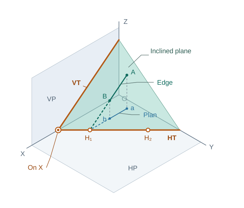
When a solid is cut by an oblique or simply inclined plane, you may be asked to determine its horizontal trace (HT) and vertical trace (VT) directly in the axonometric view:
- Draw the axonometric plan of an edge lying on the sloping surface: drop lines parallel to the -axis from both ends of the edge down to the base plane, and connect their feet. Extend both the 3D edge and its plan line until they intersect. That intersection point has zero height, so it is a piercing point on the Horizontal Plane.
- Find a second floor piercing point from another edge and connect the two points to establish the horizontal trace (HT).
- Find two piercing points on the back wall by extending edges to meet their elevation projections on the Vertical Plane; connecting them gives the vertical trace (VT).
- Check your accuracy: the HT and VT must meet at a single point on the coordinate -axis.
Reverse Projection: Recovering a 2D View
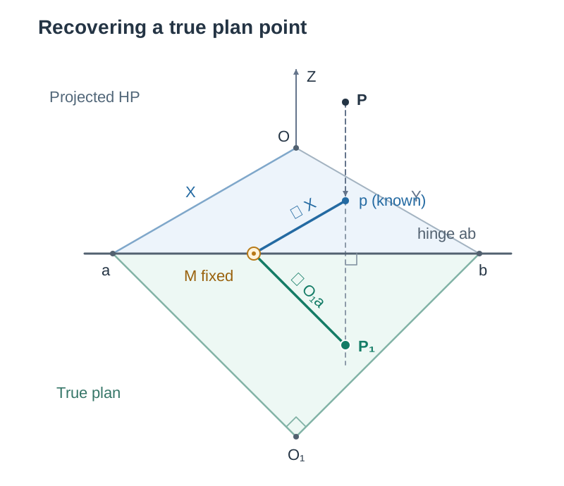
To recover a true orthographic view from a given axonometric drawing, use the rule that points on a trace do not move during rebatment:
- Rebat the required reference plane (for example, the HP about trace ) to find the true axes and .
- Pick a corner in the axonometric view. Draw a line through parallel to axis down to the base plane to get , the axonometric plan of .
- Through , draw a line parallel to the projected -axis until it meets trace at point .
- From , draw a line perpendicular to trace into the rebatted area.
- Through on trace , draw a line parallel to the true -axis .
- Where the lines from steps 4 and 5 intersect is , the true plan position of corner . Repeat for all corners to draw the true plan.
Never measure directly along projected axes with a rule. They are foreshortened by unknown factors; every distance must transfer through a point on a trace.
Answering "Determine and Indicate"
Marking schemes award separate marks for labelling constructions clearly:
- Label traces HT and VT along the lines, drawing them slightly heavier than construction lines.
- Label the axes , the vertices of the triangle of traces, and the rebatted origins .
- Write TL beside true lengths and true shape beside true surfaces.
- Keep all construction lines and projectors on the sheet, drawn lightly. Erasing them loses marks.
Key terms
- Axonometric Plane
- The inclined projection plane onto which an object and its coordinate planes of reference are orthogonally projected.
- Triangle of Traces
- The reference triangle (abc) formed where the axonometric plane cuts across the three principal planes of reference (HP, VP, and EVP).
- Orthocentre
- The intersection point of the three altitudes of a triangle; in orthogonal axonometric projection, it is always the projected origin O of the coordinate axes.
- Isometric Projection
- An axonometric projection where all three axes are equally inclined to the projection plane, giving projected axis angles of 120° and an equilateral triangle of traces.
- Dimetric Projection
- An axonometric projection where two axes make equal angles with the projection plane, producing an isosceles triangle of traces and two equal scale factors.
- Trimetric Projection
- An axonometric projection where all three axes have different inclinations, producing a scalene triangle of traces and three distinct scale factors.
- Foreshortening
- The apparent reduction in length of an edge or axis when it is tilted relative to the plane of projection.
- Isometric Scale
- A graphic scale constructed with 45° and 30° rays that reduces true lengths by the ratio cos 45° / cos 30° = sqrt(2/3) ≈ 0.816 for true isometric projection.
- Rebatment
- The descriptive geometry process of hinging a reference plane about its trace into the axonometric plane to reveal its true 90° shape.
- Axes Method
- The projection technique where reference planes are rebatted to draw orthographic views true size, and points are projected back parallel to the axes to build a 3D view.
- Horizontal Trace (HT)
- The line of intersection where an inclined or cutting plane meets the Horizontal Plane of reference.
- Vertical Trace (VT)
- The line of intersection where an inclined or cutting plane meets the Vertical Plane of reference.
Check yourself
A student sets up axes with angles of 90°, 135°, and 135°. Why can this not be an orthogonal axonometric projection?
While the angles sum to 360°, every axis angle must be strictly obtuse (greater than 90°). At 90°, the triangle of traces becomes right-angled, the orthocentre falls on a vertex, and one axis projects to zero length, producing an orthographic view rather than a 3D pictorial view.
What geometric relationship exists between the projected coordinate axes and the triangle of traces?
Each projected coordinate axis is strictly perpendicular to the opposite trace of the triangle of traces, and the projected origin O is the orthocentre of the triangle.
If an exam question provides a plan and an end view, which two traces must you rebat?
Rebat trace ab (for the plan on the Horizontal Plane) and trace bc (for the end view on the End Vertical Plane).
Why does constructing a semicircle on trace ab guarantee that angle aO1b is 90°?
By Thales' theorem, the angle subtended by a diameter at any point on a semicircle's circumference is exactly 90°, which accurately restores the true perpendicular corner between the X and Y axes.
How do you locate a piercing point on the Horizontal Plane for an inclined edge in an axonometric view?
Drop lines parallel to axis Z from both ends of the edge down to the base plane to draw its plan. Extend both the 3D edge and its plan line; their intersection point has zero height and is a piercing point on the Horizontal Plane.
In reverse projection, why must coordinates be transferred through points on a trace?
Points lying on a trace do not move when a reference plane is rebatted because the trace is the hinge line. Measuring along projected axes with a rule is invalid because projected axes are foreshortened by unknown factors.