
Most of DCG deals with objects that stay still. Dynamic Mechanisms deals with things that move: it asks you to draw the exact path — the locus — traced by a chosen point on a rolling wheel, an unwinding cord, a moving linkage or a cam follower. For Leaving Certificate Higher Level, this option covers follower displacement diagrams (Uniform Velocity, Simple Harmonic Motion, and Uniform Acceleration and Retardation); radial plate cam profiles for in-line knife-edge, roller, and flat followers, as well as reversing the process to plot a displacement diagram from a given cam profile; 3D space curves including the cylindrical helix and conical spiral; involutes of circles and regular polygons; Archimedean and logarithmic spirals; rolling curves (cycloids, epicycloids, hypocycloids, and trochoids) along with their tangents and normals; loci of points in link mechanisms and the use of a trammel; moving circles relative to lines and circles; and the layout of involute and epicycloidal gear teeth.
Kinematics, the Unified Plotting Method, and Applications
A locus is the path traced by a point moving under defined geometric or mechanical constraints. While curves such as cycloids, involutes, and spirals look completely different, you draw them using the same step-by-step approach on your drawing sheet:
- Establish the datum geometry: Draw the fixed pivots, base circles, guiding tracks, or camshaft centres accurately using light construction lines.
- Subdivide the driving movement: Divide the driving rotation or slide into equal steps. For a full revolution, 12 equal intervals of 30° are standard. For a partial swing, use at least 5 to 6 equal steps.
- Coordinate dependent positions: For each step, locate the moving parts using compass arcs of fixed link lengths, unwound arc lengths, or advancing wheel centres.
- Trace the curve: Mark each position of the tracing point () and join them with one smooth, firm curve.
The syllabus expects you to know real-world engineering applications for every curve you construct:
| Curve | Practical Engineering Applications |
|---|---|
| Involute of a circle | Spur gear tooth profiles (maintains a constant pressure angle and uniform velocity ratio). |
| Cylindrical helix | Screw fasteners, helical compression springs, worm drives, and spiral staircases. |
| Conical spiral | Conical springs (allowing solid compression into a flat profile), tapered thread cut-offs, and drill flutes. |
| Archimedean spiral | Lathe scroll chucks, cam profiles producing uniform follower lift, and tape coils. |
| Logarithmic spiral | Centrifugal pump impellers, aerodynamic exhaust casings, and profile cutters maintaining a constant rake angle. |
| Cycloid | Clockwork pendulums and machine rack teeth. |
| Epicycloid & Hypocycloid | Epicyclic (planetary) gearboxes, rotary displacement pumps, and mechanical watch gear teeth. |
| Trochoids (Superior/Inferior) | Wankel rotary engine combustion chambers (epitrochoid), tyre reflector trajectories, and tillage equipment paths. |
| Plate cams | Internal combustion engine valve operation, automatic assembly jigs, and wire-forming machines. |
Follower Displacement Diagrams: UV, SHM, and UAR
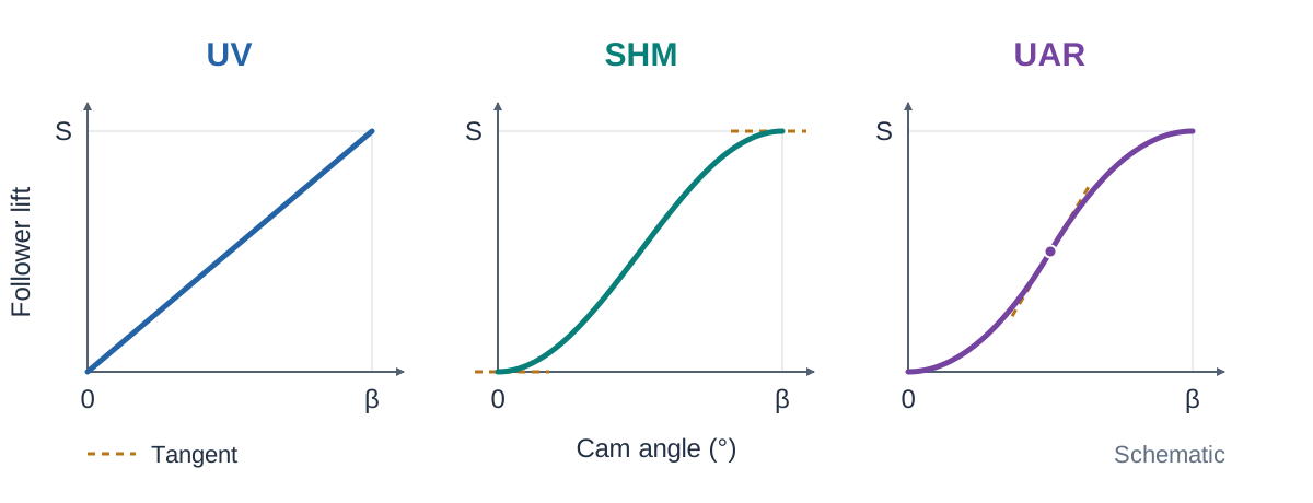
A plate cam converts continuous rotary motion into precise reciprocating linear movement. Before drawing the cam, you must construct a displacement diagram, which plots camshaft rotation ( to ) along the horizontal axis against linear follower lift (stroke ) along the vertical axis.
Types of Motion
- Uniform Velocity (UV): The follower moves at a constant speed, shown as a straight sloping line. Sudden shifts from UV to dwell cause sharp velocity steps and theoretical shock loading.
- Simple Harmonic Motion (SHM): Delivers smooth acceleration and deceleration from rest. On the vertical axis for that motion interval, draw a semicircle whose diameter equals the lift stroke. Divide this semicircle into the exact same number of sectors as the horizontal angular interval (for example, 6 divisions of for a span, or 4 divisions of for a span). Project horizontal lines across from each point on the semicircle to meet the matching angle ordinates.
- Uniform Acceleration and Retardation (UAR): The follower accelerates uniformly for the first half of the stroke and retards uniformly for the second half, forming two parabolas that meet at mid-stroke, where the follower is moving fastest and the two curves share the same slope. With 6 equal intervals, the distances moved in successive intervals are in the ratio — small steps at the start while the follower is speeding up, large steps at mid-stroke, small steps again as it slows. The sum of these 6 increments is 18 units:
The cumulative heights plotted at successive stations are and units. If 8 divisions are required, the increments are (totaling 32 units), giving cumulative heights of and units.
- Dwell: The follower remains stationary at a constant height, represented by a horizontal line.
Working Backwards: Displacement Diagram from a Given Cam Profile
When an exam question supplies a finished cam profile and asks for the displacement diagram:
- Find the cam centre and draw radial lines at regular 30° intervals, numbered in the direction of follower rotation relative to the cam (opposite to cam rotation).
- Draw the base circle (the smallest circle concentric with the shaft that touches the profile).
- For a knife-edge follower, measure the distance from the cam centre to the profile along each radial line. The lift is that measured distance minus the base circle radius.
- For a roller follower, draw the roller circle touching the profile at each radial station, mark its centre, and measure from the cam centre to that centre. The lift is the measured distance minus the prime circle radius. For a flat follower, draw the flat face tangent to the profile perpendicular to each radial line and measure to the contact line.
- Set out the horizontal axis from to , plot the measured lifts as vertical ordinates, join them smoothly, and label the motion types.
Radial Plate Cam Profile Construction
Cam profile layout relies on kinematic inversion: imagine the cam held stationary while the follower rotates around it in reverse. If the camshaft turns clockwise, number your radial divisions in an anticlockwise sequence around the cam centre.
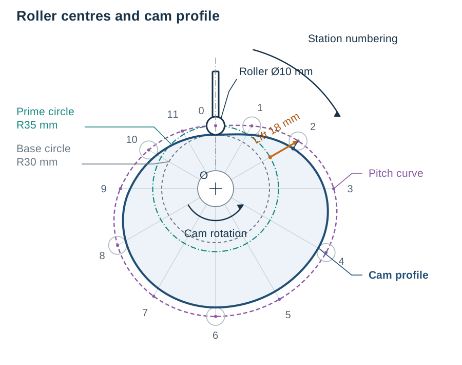
Follower Types and Reference Geometry
- Base Circle: The smallest circle concentric with the camshaft that touches the working cam profile.
- Prime Circle: The reference circle passing through the centre of a roller follower at its nearest approach, concentric with the camshaft:
- In-Line Knife-Edge Follower: Divide the base circle into radial lines spaced at the motion increments, numbered opposite to rotation. Transfer the vertical lift from the displacement diagram directly outward along each radial line, starting from the base circle. Draw a smooth curve through these points.
- In-Line Roller Follower (HL): Divide the prime circle into radial lines numbered opposite to rotation. Step each displacement outward from the prime circle along its radial line to locate the roller centres (this path is the pitch curve). At each centre, draw a light circle with the roller radius. Finish the cam profile as one smooth, firm curve touching the inside of every roller circle.
- In-Line Flat Follower (HL): Measure displacements outward from the base circle along each radial line. Through each plotted point, draw a line perpendicular to that radial line, representing the flat follower face. The cam profile is the smooth continuous envelope curve drawn tangent to the inside of these flat face lines.
Rolling Curves: Cycloids, Epicycloids, Hypocycloids and Trochoids
Rolling curves are traced by points on a generating circle that rolls without slipping along a datum line or arc.
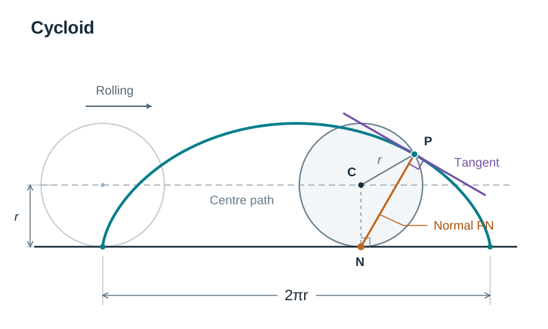
- Cycloid: Traced by a point on the rim of a circle of radius rolling along a straight line. For one full turn, the circle advances a baseline distance equal to its circumference, . The centre moves along a line parallel to the base at height . Divide both the circumference and baseline into 12 equal parts. From each advancing centre , swing an arc of radius to cut the horizontal guide line projected from division on the circle.
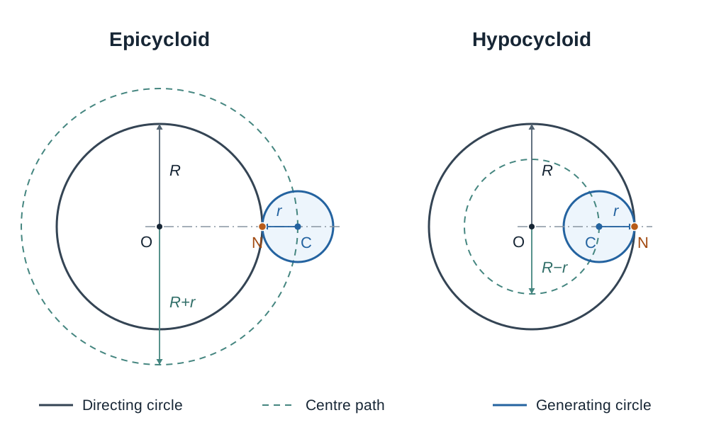
- Epicycloid and Hypocycloid: An epicycloid forms when a circle rolls on the outside of a circular arc of radius ; a hypocycloid forms when it rolls on the inside. To find the angle subtended on the directing arc for one complete revolution, equate arc lengths:
The path of centres is an arc concentric with the directing arc, drawn at radius for an epicycloid, or for a hypocycloid. Divide into 12 equal sectors to locate centres to . Draw concentric guide arcs from the main centre through each division of the rolling circle. From each centre , strike an arc of radius to cut guide arc , taking the intersection on the trailing side of (the side the wheel has already rolled over).
- Trochoids (Superior and Inferior): Traced by a point rigidly fixed to the wheel at a distance from the centre. An inferior trochoid (, such as a spoke reflector) produces a wave-like curve. A superior trochoid () forms loops extending beyond the track. When rolling on an arc, use the same subtended angle , but strike arcs of radius from each centre onto concentric guide arcs spaced at radius .
- Tangents and Normals from the Instantaneous Centre: At any instant, the contact point between the rolling wheel and the directing path is the instantaneous centre of zero velocity. The line joining point on the curve to is the normal. The tangent is perpendicular to through .
Finding the Contact Point at Any Given Point P
If point is marked on a finished curve and you do not know the wheel centre:
- On a cycloid, swing an arc of radius from to cut the line of centres at . Drop a perpendicular from to the directing line to find contact point . Line is the normal; the tangent is perpendicular to at .
- On an epicycloid or hypocycloid, swing radius from to cut the arc of centres (radius or ) at . Join the directing arc centre through ; where crosses the directing arc is . Line is the normal.
- On a trochoid, use radius from to find centre , then locate as above.
Spirals, Helices, and Space Curves
Archimedean Spiral
A point moves outward at uniform speed along a radius vector while that vector rotates at constant angular speed (). The distance between successive convolutions along any ray is constant. Divide the rotation and the radial gain into the same number of equal parts (typically 12) and connect the corresponding intersections.
Tangent to an Archimedean Spiral (HL)
The spiral constant is the radial gain per radian:
To construct the normal and tangent at point :
- Join pole to .
- At , draw a line perpendicular to and step off , turning from through 90° in the same rotational sense in which the spiral is generated (the direction the radius sweeps). If the spiral uncoils anticlockwise and is at 150°, lies on the 240° ray.
- Join to : line is the normal. The tangent is perpendicular to through .
Logarithmic Spiral (HL)
The radius grows in geometric progression for equal angular steps (). The curve cuts all radius vectors at a constant angle. If two consecutive radii and are known, the next radius is .
Constructing a Cylindrical Helix
A helix winds around a cylinder at uniform angular and axial speed:
- Draw the plan (a circle of diameter ) and elevation (a rectangle of height equal to the pitch) of the cylinder.
- Divide the plan circle into 12 equal parts and number them in the direction of rotation.
- On the elevation, divide the pitch height into the same 12 equal parts and draw horizontal lines.
- Project each numbered plan point up to its matching horizontal height line.
- Join the points with a smooth curve. Draw the front half firm and the back half dashed as a hidden line.
- A single helix advances by its pitch in one revolution. On a multi-start thread the axial advance in one turn is called the lead, and it equals the number of starts multiplied by the distance between adjacent thread crests (so a double-start thread advances twice that crest spacing per turn).
Constructing a Conical Spiral
A conical spiral winds around a cone from base to apex:
- Draw the plan circle and the elevation triangle of the cone.
- Divide the plan base circle into 12 equal parts and draw 12 radial lines.
- Divide the cone height in elevation into 12 equal parts and draw horizontal level lines.
- Where each horizontal line cuts the cone outline in elevation, read off the radius at that height and swing that radius onto the matching radial line in plan.
- Connect the plan points to produce an Archimedean spiral.
- Project each plan point vertically up to its height line in elevation and join them smoothly.
Involutes, Linkages, Trammels, and Moving Circles
Involute of a Circle and Regular Polygon
An involute is traced by the end of a taut string unwinding from a shape.
- Circle: Divide the circumference into 12 equal parts and draw tangents at each station pointing in the unwinding direction. Along tangent , step off length . Join points smoothly. The normal at any point is the tangent drawn from to the base circle touching at ; the tangent to the involute is perpendicular to at .
- Regular Polygon: The string unwinds from sharp corners, so the curve is a chain of circular arcs. Extend each side of the polygon in the unwinding direction. From vertex , swing an arc from the free end with radius equal to the unwound side length to hit the extension of side . With centre at and radius equal to two side lengths, swing to the next extension. Continue round, increasing the radius by one side length at each vertex.
Loci from Link Mechanisms
A link mechanism is an assembly of rigid bars pinned together. Since links cannot stretch, every pin position can be plotted with a compass:
- Draw the mechanism in its starting position and identify fixed pivots, sliders, and guided pins.
- Divide the movement of the driving crank into equal steps (12 steps of 30° for a full turn, or 5 to 6 steps for a partial swing).
- For each step, locate the driven pin by swinging compass arcs equal to true link lengths from known pin positions onto guide tracks.
- If a link slides through a swivel, draw a line from the pivot through the swivel centre and step the link length along that line.
- Mark every position of the tracing point () and join them with a smooth curve.
Using a Trammel
A trammel is a straight strip of paper or card on which true pin distances are marked. Mark tracing point and the constrained pins on the strip edge. Lay the strip on the drawing so the pin marks lie on their respective guide tracks, and prick point . Repeat for 12 positions and join the points. For an ellipse, mark semi-minor distance from to , and semi-major distance from to ; keeping on the major axis and on the minor axis guides along the ellipse.
Loci of Moving Circles
When tracking a moving circle, focus on its centre:
- Rolling on a line: centre moves parallel to the line at distance .
- Rolling on a circle of radius : centre moves on a circle of radius (exterior) or (interior).
- Circle touching a line and a fixed circle (centre , radius ): its centre is equidistant from focus and a line parallel to the datum at distance , forming a parabola.
- Circle touching two fixed circles externally: difference of distances to centres is constant, forming a hyperbola. If the moving circle lies inside one fixed circle, touching it internally, while touching the other externally, the sum of the distances to the two centres is constant and equal to R₁ + R₂, so the locus is an ellipse with those centres as foci.
Gear Profiles: Involute and Epicycloidal Teeth (Higher Level)
Gears transmit positive drive and constant velocity ratios between rotating shafts. Higher Level candidates must know both involute and epicycloidal tooth constructions.
Standard Involute Proportions
Tooth sizes are defined by the metric module ():
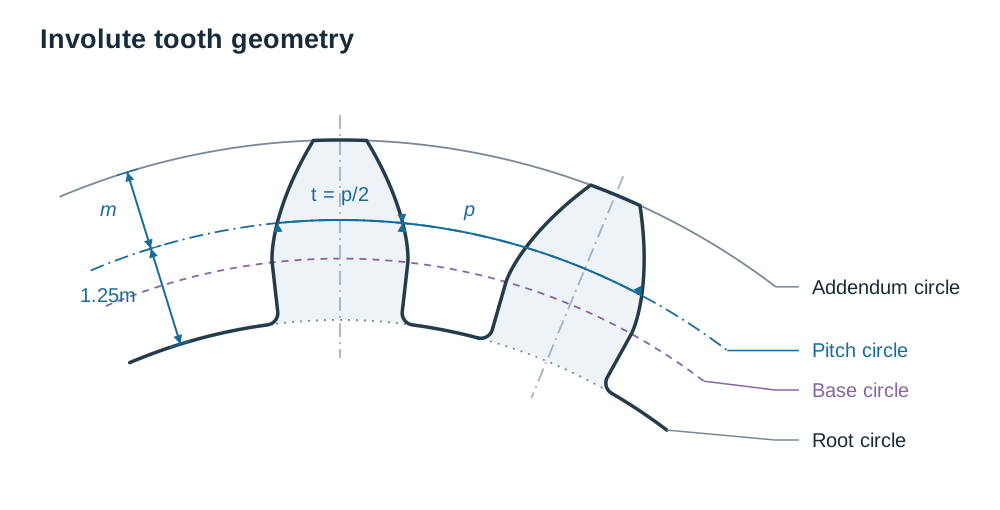
- Pitch Circle Diameter (PCD): Theoretical rolling diameter where mating gears touch: , where is tooth count.
- Circular Pitch (): Distance between corresponding points on adjacent teeth: .
- Addendum: Radial height above the pitch circle: .
- Dedendum: Radial depth below the pitch circle: .
- Pressure Angle (): Angle between the tooth normal and pitch tangent, standardised at .
- Base Circle Diameter: The circle from which the involute unwinds:
- Tooth Thickness: Measured along the pitch circle: .
Always check question data: if an exam specifies different proportions (such as a pressure angle or dedendum of ), use the stated values.
Constructing the Involute Tooth
- Draw concentric addendum, pitch, base, and dedendum circles.
- Unwind an involute from the base circle outward to the addendum circle.
- Step off tooth thickness along the pitch circle.
- Mirror the involute across the tooth's radial centreline.
- Below the base circle, draw straight radial lines down to the root circle, blending with fillets.
Epicycloidal (Cycloidal) Gear Teeth
Common in horology (clocks and watches), cycloidal teeth use a separate generating circle:
- Draw root, pitch, and addendum circles.
- Roll the generating circle along the outside of the pitch circle from the pitch point to create an epicycloid up to the addendum circle. This curve forms the tooth face.
- Roll the same generating circle along the inside of the pitch circle to create a hypocycloid down to the root circle. This forms the tooth flank.
- Mirror both curves across the tooth radial centreline. If the generating circle diameter equals the pitch circle radius, the hypocycloid becomes a straight radial line.
Key terms
- Locus
- The path traced out by a geometric point moving according to fixed mathematical or mechanical constraints.
- Displacement Diagram
- A linear graph plotting camshaft rotation angle (0° to 360°) on the horizontal axis against follower linear displacement on the vertical axis.
- Base Circle
- The smallest circle concentric with the camshaft that touches the working profile of a plate cam.
- Prime Circle
- The reference circle passing through the centre of a roller follower at its nearest approach, concentric with the camshaft.
- Pitch Curve
- The locus traced by the centre of a roller follower relative to a stationary cam.
- Kinematic Inversion
- The drawing technique of holding the cam stationary and rotating the follower in reverse around it to establish the required profile.
- Instantaneous Centre
- The stationary pivot point about which a moving body rotates at a specific instant; for a rolling wheel, it is the contact point on the track.
- Involute
- The planar curve traced by the free end of a taut string as it unwinds from the perimeter of a base circle or polygon.
- Pitch of a Helix
- The axial distance advanced by a helix during one complete revolution of 360°.
- Archimedean Spiral
- A planar curve traced by a point moving outward along a radius vector at constant speed while the vector rotates at constant angular speed.
- Logarithmic Spiral
- An equiangular spiral whose radius grows in geometric progression for equal angular steps, cutting all radius vectors at a constant angle.
- Cycloid
- The locus traced by a point on the circumference of a circle rolling without slipping along a straight line.
- Epicycloid
- The locus traced by a point on the circumference of a circle rolling without slipping along the outside of a circular directing arc.
- Hypocycloid
- The locus traced by a point on the circumference of a circle rolling without slipping along the inside of a circular directing arc.
- Module
- The standard metric unit of gear tooth size, calculated as the pitch circle diameter divided by the number of teeth.
- Pressure Angle
- The angle between the common normal to two meshing gear teeth and the common tangent to their pitch circles, standardised at 20°.
Check yourself
What is the formula linking the base circle radius and prime circle radius for an in-line roller follower of radius r?
Prime Circle Radius = Base Circle Radius + r.
A circle of radius 25 mm rolls along the outside of a circular directing arc of radius 150 mm. What angle is subtended at the directing arc centre for one complete revolution of the wheel?
60°, calculated as θ = 360° × (r / R) = 360° × (25 / 150) = 60°.
How do you find the normal at any point P on a cycloid or epicycloid?
Draw a straight line from point P to the instantaneous point of contact N between the generating circle and the directing datum line or arc.
A follower rises 36 mm with UAR across 6 equal time divisions. What is its displacement after the first division?
2 mm, because 6 divisions follow a 1:3:5:5:3:1 ratio totaling 18 units; 1 unit = 36 mm / 18 = 2 mm.
What 2D dynamic curve does a conical spiral form when projected onto the horizontal plane (plan view)?
An Archimedean spiral, because the radius decreases at a constant rate per angular increment as the path approaches the cone apex.
A crank rotates through 90° and drives a rod whose far end slides along a straight line. How many positions should you construct, and how do you locate the far end in each position?
Divide the 90° rotation into at least 5 or 6 equal angular steps; for each crank pin position, set your compass to the true rod length, centre it on the crank pin, and strike an arc cutting the straight guide line.
When given a cam profile and asked to construct its displacement diagram, what reference measurement do you subtract from each radial distance?
Subtract the base circle radius for a knife-edge or flat follower, or subtract the prime circle radius if you have measured to the centre of the roller follower.