
Geologic Geometry, also known as geological geometry, uses the principles of descriptive geometry—lines, planes, and intersections—to solve three-dimensional problems on topographic maps and beneath the ground. The syllabus divides into two main families: earthworks on the ground surface (cuttings and embankments for level and inclined roads or platforms) and the geometry of planar strata below it (strike, dip, apparent dip, thickness, outcrop paths, and skew boreholes). Most underground problems rely on one core descriptive geometry principle: construct a level line on the plane, then project an auxiliary view looking along it. Under the Leaving Certificate examination adjustments for 2027, Section C contains five 60-mark option questions, from which candidates answer any one.
Topographic Contours, Profiles, and Survey Notation
A contour line joins points of equal elevation above a chosen reference datum, typically mean sea level. The contour interval is the constant vertical distance between successive contours, usually 5 m or 10 m on examination maps. Contours spaced closely indicate steep terrain, widely spaced contours show gentle slopes, and V-shaped contours pointing uphill reveal a river valley.
All drawings must observe standard map notation. Bearings are measured clockwise from north and written with three digits (such as 075°, 180°, or 355°), or as quadrant bearings (such as N75°E or S20°W). A north arrow should always be drawn on your plan.
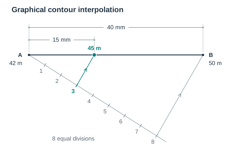
When spot heights are surveyed across a grid, intermediate contour positions are found by linear interpolation, assuming a uniform slope between adjacent points:
For example, if grid point has an elevation of 42.0 m and point is at 50.0 m across a 40 mm grid square side, the 45.0 m contour lies of the distance from to , which is along . This division can also be done graphically by swinging a temporary ray from , stepping off eight equal units with dividers, joining the eighth mark to , and projecting parallels back onto .
A ground profile is a vertical section through the landscape cut along a marked line, such as . To draw it, set up horizontal datum lines spaced according to the contour interval at the drawing scale. Project perpendicular lines from each point where crosses a contour to its corresponding elevation line, and connect the plotted points with a smooth curve.
Profiles are regularly used to evaluate intervisibility between two stations. Draw a straight line of sight connecting an observer's eye level to the target. If the terrain profile rises above this line at any point, the target is obscured. To determine the minimum mast height needed at an obscured station to restore visibility, draw a line of sight from the observer grazing the highest intervening ridge crest and extend it to meet the vertical line at the target.
Earthworks for Level Formations: Cuttings, Embankments, and Corners
Earthworks alter the natural ground to create a horizontal road, railway, or building platform at a designated formation level. Where natural ground rises above formation level, ground is excavated to form a cutting. Where natural ground falls below formation level, fill material is placed to form an embankment.
Gradients are expressed as 1 in , meaning 1 unit of vertical rise or fall per units measured horizontally. Side slopes of earthworks are expressed as a vertical-to-horizontal ratio (). A cut slope of means 1 m vertical to 1 m horizontal (), while a fill slope of means 1 m vertical to 2 m horizontal (). Compaction makes undisturbed cut earth firmer than placed fill, so cutting slopes are typically steeper. On plan, the horizontal spacing between successive side-slope contours is given by:
For a straight formation edge, the side-slope surface is a plane, so its contours are straight lines parallel to the edge, spaced at .
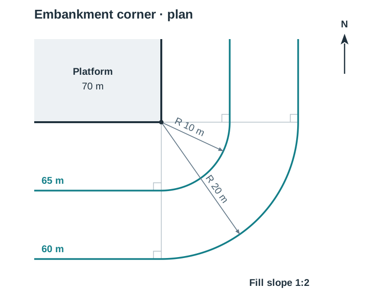
At a corner of a level platform or a square road end, the sloping earthwork forms a right circular cone whose apex is at the corner station. The slope contours around the corner are circular arcs concentric with the corner. For a height difference between the formation level and a slope contour, the arc radius is:
For example, at a level embankment corner of formation level 70 m with fill slope and 5 m contour interval, the 65 m slope contour () turns the corner as an arc of radius , meeting the straight 65 m slope contours tangentially. The 60 m arc has radius . For a road that curves in plan, the slope contours are concentric arcs offset from the curved edge by for each contour interval.
Mark each point where a side-slope contour intersects a natural ground contour of the same elevation. Connect these points with a smooth curve. Label the boundaries clearly: the crest is the top of a cutting, and the toe is the bottom of an embankment. Where the ground contour matches the formation level exactly, this is a point of zero cut and fill, where the boundary line must touch the formation edge.
Earthworks for Inclined Roads: The Cone Method
When a road rises or falls along a gradient, the formation level changes continuously along its length. Because the road edge slopes, the side-slope envelope is tangent to a series of right circular cones whose apexes lie on the road edge.
Every generator on a right cone of revolution has a constant slope. In plan, because the cone axis is vertical, the apex and the circular base share the exact same centre point. For a vertical height difference between the apex and the base level, the plan radius of the base circle is:
- Cut cones: Excavations widen upward into higher ground. The cone opens upward from its apex at a lower formation station, so its base circle is drawn at a higher elevation.
- Fill cones: Embankments widen downward into lower ground. The cone opens downward from its apex at a higher formation station, so its base circle is drawn at a lower elevation.
Whether a station requires cut or fill is determined by comparing the natural ground level with the formation level at that specific location, not by which side of the road you are looking at. A road traversing a hillside can have a cutting on one side and an embankment on the other, or transition from cut to fill along its length.
To construct the side-slope contours on a straight, uniformly graded road edge:
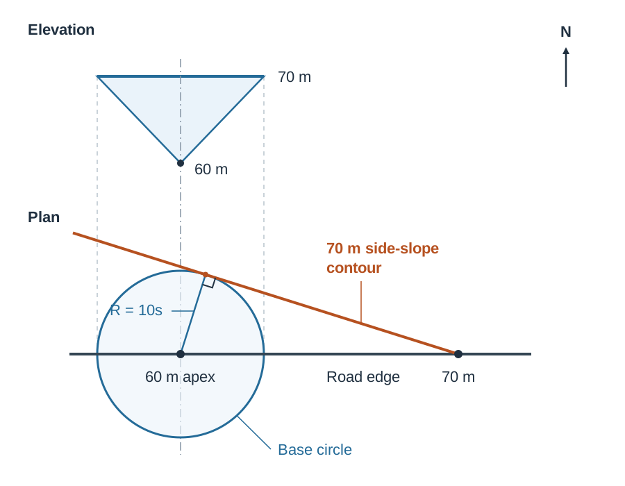
- Choose an apex station on the road edge at a known formation level (for example, 60 m).
- Select another formation level (for example, 70 m, where ) and calculate the base circle radius .
- Draw the base circle centred directly on the 60 m apex station in plan.
- From the road edge at the 70 m station, draw a straight line tangent to this base circle. This tangent line is the 70 m side-slope contour.
- Because a straight road edge at a uniform gradient creates a planar side slope, all other side-slope contours are parallel straight lines spaced at perpendicular intervals of .
If the inclined road curves in plan, the side slope is not planar. In that case, you must draw the base circle at each station and draw the side-slope contour as a smooth curve tangent to all base circles of that level.
Stratum Orientation: Strike, True Dip, and Apparent Dip
A planar geological stratum, such as an ore vein or rock layer, is bounded by an upper surface of the stratum (the hanging wall) and a lower surface (the footwall). In descriptive geometry, both boundaries are treated as parallel planes. Most stratum problems come down to one unifying principle: find a level line on the plane, then look along it.
Imagine a stiff sheet of card propped up at an angle on a table. A pencil laid horizontally across the card represents the strike. Release a marble on the card: it rolls straight down along the steepest line of slope, which is the dip direction. The angle between this steepest line and the horizontal table is the true dip. Now roll the marble diagonally across the card: it still rolls downhill, but at a gentler incline. That gentler angle is the apparent dip.
- Strike: The compass bearing of a horizontal line drawn on the stratum plane. Being horizontal, it shows in true length in plan.
- True Dip: The maximum angle of inclination between the stratum and the horizontal plane, measured perpendicular to the strike.
- Dip Direction: The compass direction in which the stratum falls, always at 90° to the strike line in plan.
- Apparent Dip: The angle of inclination seen in any vertical section not taken perpendicular to the strike. It is always less than the true dip, equal to true dip when the section is at 90° to strike, and zero along the strike.
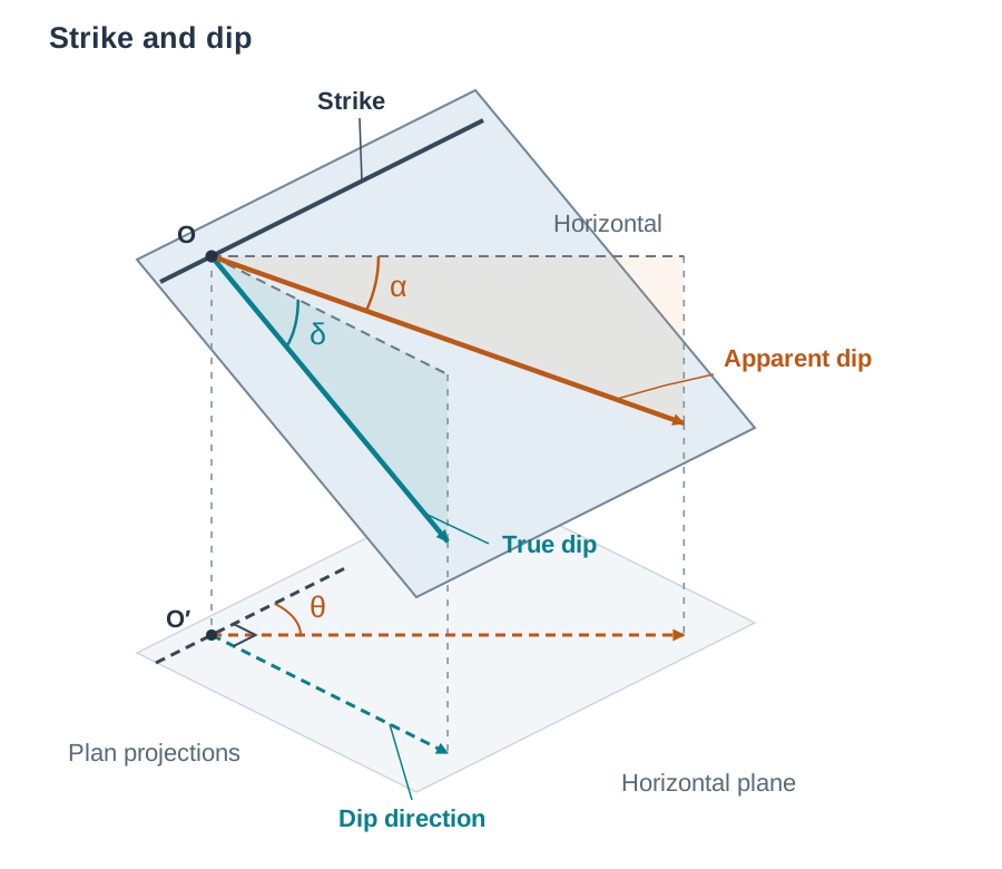
To find strike from three vertical boreholes , , and penetrating the upper surface:
- Plot , , and in plan and elevation from their map positions and levels.
- From the intermediate-height point in elevation, draw a horizontal line across the triangle to cut the opposite side at point .
- Project to the corresponding side in plan. Connect this point to the intermediate point in plan. This line is a level line on the stratum; its compass bearing is the strike.
The rule that governs every auxiliary view in this topic is: projectors from plan run perpendicular to the ground line , so the line of sight is at 90° to . Therefore, to look along the strike, set at right angles to the plan strike line. Project points into this auxiliary view, taking heights directly from the elevation datum. If your projection is accurate, all points on the upper surface will lie on one straight line. This is the edge view of the stratum, and the fact that the points line up is your self-check that the drawing is correct. Measure the angle between this edge view and to find the true dip.
Graphical Method for Apparent Dip
To determine the apparent dip in a specified section direction through point on the stratum:
- Draw the required section line through in plan.
- In plan, draw two structure contours (lines parallel to the strike at known levels, such as 60 m and 70 m) that cross the section line.
- Set up an auxiliary ground line parallel to the section line in plan, so the line of sight is perpendicular to it and the section line appears in true length.
- Project the two contour intersection points perpendicular to , set off their heights above , and join them. Measure the angle this line makes with using a protractor; this is the apparent dip .
You can verify your graphical result using the formula:
where is the true dip and is the angle between the section line and the strike in plan.
If a question gives two apparent dips and in two known directions from a common point , calculate or step off the horizontal distance needed for an equal vertical drop : and . Mark these points along the two direction lines from in plan. Joining the two points gives a line where both points are at the same elevation, which is a level line on the stratum—its bearing is the strike.
Stratum Thickness, Outcrop Profiles, and Depth Calculations
The true thickness of a stratum is the perpendicular distance between its parallel upper and lower surfaces. Measuring vertical depth through the seam gives an exaggerated value (). The true thickness relates to vertical thickness by:
To find true thickness graphically, obtain the edge view of the upper surface in an auxiliary elevation looking along the strike. Project a known penetration point on the lower surface (such as where a borehole exits the stratum) into this auxiliary view. Draw a line through this point parallel to the upper surface edge view. The perpendicular distance between these parallel lines, converted by the map scale, is the true thickness.
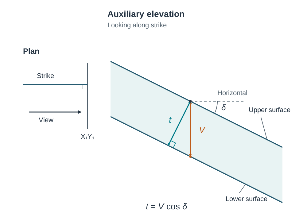
Outcrop Profiles
An outcrop is the exposed surface trace where an underground stratum meets the ground surface:
- In the auxiliary elevation showing the edge views of the upper and lower surfaces, identify where each edge line intersects each contour height (e.g., 50 m, 60 m, 70 m, 80 m).
- Project these points back into plan as lines parallel to the strike. These are structure contours—level lines on the stratum planes.
- In plan, mark every point where a structure contour intersects a natural ground contour of the identical elevation (e.g., the 60 m upper structure contour crossing the 60 m ground contour).
- Join these matching points with a smooth curve to delineate the outcrop line of the upper surface.
- Repeat the process for the lower surface. Lightly hatch the area between the two curves to show the exposed band of rock.
If an outcrop is already drawn on a map and you are asked to determine strike, dip, and thickness, work backwards: find where the outcrop line crosses ground contours, label the levels, and join two points of equal level to find the strike line. Then project an auxiliary view perpendicular to strike to obtain the edge view and true dip.
Depth of Stratum Below a Surface Point
To find the depth of a proposed vertical borehole at point :
- Read or interpolate the ground elevation at from the map contours.
- Interpolate the stratum elevation directly beneath using the structure contours.
- The required drilling depth to reach the top of the seam is:
To penetrate completely through the seam, the vertical borehole must continue downward by a distance of .
Skew Boreholes in Mining Explorations
A skew borehole is drilled at an angle rather than vertically, so it runs obliquely downwards through the ground. The critical descriptive geometry consequence is that the borehole is oblique to both principal planes of reference: its plan view is shorter than its actual length. Any distance specified "along the borehole" is a true length and must be stepped off in a view where the borehole appears in true length, never directly in plan or standard elevation.
To plot an inclined borehole drilled from collar station (surface elevation known) on bearing at an inclination angle below the horizontal:
- Plot in plan and elevation.
- Draw the borehole centreline in plan from along its given compass bearing.
- Set up an auxiliary ground line parallel to the plan of the borehole. In this auxiliary view, the line of sight is perpendicular to the hole, so the borehole appears in true length.
- In the auxiliary view, draw the borehole from angled downward at below . Using dividers, measure the true drilling distances along this line to locate where the drill enters the upper surface () and exits the lower surface ().
- Project and back perpendicular to onto the plan centreline to establish their plan coordinates, and transfer their heights from the auxiliary view into the elevation.
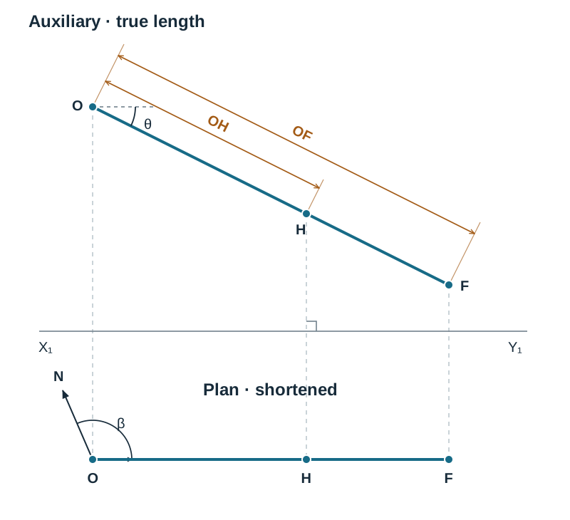
When two skew boreholes penetrate a planar stratum, they give two points on the upper surface () and two points on the lower surface (). Because the upper and lower surfaces are parallel planes, the upper surface must contain a line parallel to the lower surface line :
- Draw line on the upper surface and line on the lower surface in both plan and elevation.
- Through point , construct a line parallel in plan and parallel in elevation to line .
- The two intersecting lines through (line and the line parallel to ) define the plane of the upper surface.
- Construct a level line on this plane in elevation and project it to plan to establish the strike.
- Project an auxiliary view looking along the strike ( perpendicular to strike) to show the upper surface as an edge view and measure true dip.
- Project into this view, draw the lower surface parallel to the upper surface, and measure the perpendicular distance between them to determine true thickness.
Key terms
- Contour Line
- A line on a map connecting points of equal elevation above a reference datum, usually mean sea level.
- Contour Interval
- The constant vertical distance in elevation between successive contour lines on a map.
- Interpolation
- The mathematical or graphical method of calculating the position of intermediate contours between known spot heights by assuming a uniform slope.
- Formation Level
- The finished design elevation of an engineered ground surface, such as a roadway or construction platform.
- Side Slope Ratio
- The ratio of vertical rise or fall to horizontal distance (1 : s) defining the inclination of an engineered earthwork.
- Cutting
- An earthwork excavation created where existing ground rises above the required formation level; its upper boundary is the crest.
- Embankment
- An earthwork fill structure built up where existing ground falls below the formation level; its base boundary is the toe.
- Point of Zero Cut and Fill
- A point where the natural ground contour crosses the formation edge at an elevation equal to the formation level, marking the transition between excavation and fill.
- Upper Surface (Hanging Wall)
- The upper planar boundary surface of an inclined geological stratum or vein; exam papers typically call this the top or upper surface.
- Lower Surface (Footwall)
- The bottom planar boundary surface of an inclined geological stratum, parallel to the upper surface.
- Strike
- The compass bearing of a horizontal line lying on the planar surface of an inclined stratum.
- True Dip
- The maximum angle of inclination between an inclined stratum and the horizontal plane, measured perpendicular to the strike.
- Dip Direction
- The compass direction of maximum downward slope of a stratum, oriented at 90° to the strike line in plan.
- Apparent Dip
- The angle at which a stratum appears to slope in a vertical section that is not perpendicular to the strike; it is always less than true dip.
- True Thickness
- The perpendicular distance measured at right angles between the parallel upper and lower surfaces of a stratum.
- Structure Contour
- A level line drawn at a specific elevation on the planar surface of an underground stratum, running parallel to the strike.
- Outcrop
- The line or exposed surface band where an underground geological stratum intersects the natural terrain surface.
- Skew Borehole
- A borehole drilled at an angle rather than vertically, resulting in a plan projection shorter than its actual true length.
Check yourself
What geometric relationship always exists between the strike line and the dip direction in plan?
The dip direction is always oriented exactly perpendicular (at 90°) to the strike line in plan, pointing toward the falling side of the stratum.
A roadway embankment has a side slope ratio of 1 : 2. If the contour interval is 5 m, what is the horizontal spacing between side-slope contours on the plan?
10 m (calculated as Δd = interval × s = 5 × 2 = 10 m).
Why must the auxiliary baseline X1Y1 be drawn perpendicular to the strike line in plan to find true dip?
Projectors from plan run perpendicular to X1Y1. Placing X1Y1 perpendicular to the strike directs the line of sight parallel to the strike line, viewing the horizontal level line as a point and the entire stratum as a single line (an edge view).
A stratum has a true dip of 40°. What is the apparent dip in a vertical section cut at an angle of 30° to the strike line?
23° (calculated as tan α = tan δ × sin θ = tan 40° × sin 30° = 0.8391 × 0.5000 = 0.4195, giving α = tan⁻¹(0.4195) = 22.8° ≈ 23°).
At a station on a road, the formation level is 54 m and the natural ground contour at that point is 61 m. Are you in a cutting or on an embankment, and which way does the slope cone open?
Natural ground (61 m) is above the formation level (54 m), so it is a cutting. The cutting cone opens upward into higher ground, meaning its circular base is drawn at an elevation above the apex station.
A vertical borehole passes through 10 m of ore in a seam dipping at 30°. What is the true thickness of the seam?
8.66 m (calculated as t = V cos δ = 10 × cos 30° = 10 × 0.8660 = 8.66 m).