
Take a cardboard cereal box, cut along its edges, and flatten it out. That flat shape is a surface development: the exact 2D pattern you would cut from sheet material to construct the 3D solid. Peel a paper label off a tin or wrap a template around a cone and you have carried out the exact reverse operation, an envelopment. Every line drawn on a development must represent a true length, and every flat surface must appear in its true shape. Because standard orthographic projections foreshorten any line or plane inclined to the projection planes, dimensions cannot simply be lifted from elevation or plan without verifying that the feature is parallel to that plane. Everyone studies the development and envelopment of right solids, frustra, and composites, and everyone must be able to determine and project true distance lines. Two areas are Higher Level only: developing and enveloping oblique prisms and pyramids, and completing the intersection details of regular and oblique solids whose axes are parallel to a principal plane, followed by their surface development. To choose the correct development method immediately, apply this four-part rule: 1. Lateral edges or surface generators parallel: parallel-line development (stretch-out baseline = perimeter or circumference ). 2. Lateral edges or generators converging at a single apex: radial-line development (radial arcs struck from the apex). 3. Lateral edges not parallel and apex off-centre, or connecting different duct profiles: triangulation (each edge found as an individual true length). 4. Oblique prism or oblique cylinder: right-section method (a transverse cutting plane perpendicular to the inclined edges unfolds into a straight baseline).
Core Principles and Graphical Conventions
Every surface development requires two conditions: every line must be drawn at its true length (TL), and every flat surface must appear in its true shape (TS). Because standard elevation and plan views foreshorten lines that slope away from the projection planes, you must test whether a line is parallel to the ground line before scaling it.
In sheet metal work, packaging, and technical drawings, standard line conventions communicate how the flat pattern behaves:
- Draw the outline of the pattern firm and continuous. This represents a cut edge, and the examiner reads the finished boundary from it.
- Draw fold lines inside the pattern thinner than the outline, using either thin continuous lines or dashed lines, so a crease is never mistaken for a cut.
- Leave all construction work visible. Generators, rotation arcs, projection rays, and true-length right-angled triangles must remain light and clean to secure method marks. Never rub out your construction.
Unless an exam question states otherwise, always open a development along the shortest seam or generator. In practical manufacturing, minimising seam length reduces welding, bonding, joint failure, and material waste.
Parallel-Line Developments: Right Prisms and Cylinders
Parallel-line development applies to solids bounded by parallel lateral edges or parallel surface generators. For right solids standing upright on the horizontal plane, these lines are vertical in space and appear at their true length in the front elevation.
Right Prisms
For a right prism, the development unrolls along a straight, horizontal stretch-out line equal in total length to the base perimeter. Each individual base edge length is taken directly from the plan (where the horizontal base is seen in its true shape) and stepped consecutively along this baseline. Perpendicular fold lines are erected at each station. If the prism is cut by an inclined plane, the cut heights are projected horizontally across from the elevation onto their matching fold lines. Adjacent points are connected with straight lines because each lateral face of a prism is flat.
Right Cylinders and Surface Generators
Because a cylinder has a continuous curved surface with no sharp corners, we divide its perimeter using imaginary surface lines called generators:
- Divide the circular plan into 12 equal sectors of each, which is done quickly with a set square worked around the centre point, and number the stations 1 to 12.
- Project these division points vertically into the front elevation as parallel generator lines.
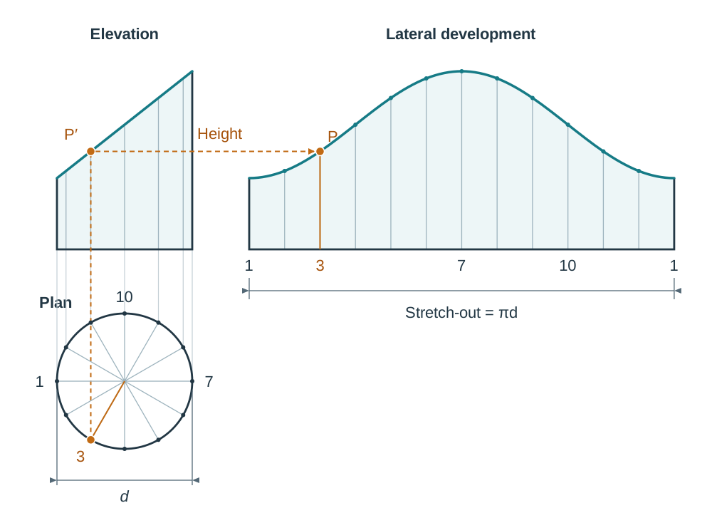
- Lay out the stretch-out line along the ground line. Its total length equals the circumference of the cylinder (). Divide this line into 12 equal segments and erect vertical generators at each division.
- Project the cut heights horizontally across from the elevation to meet the corresponding generator lines on the development.
- Draw a smooth, continuous freehand curve through the plotted cut points. Never join points on a curved surface with straight lines.
To locate an isolated surface point on a cylinder (a common Section A task, such as the scoop on the 2026 paper), locate the generator passing through in plan, measure its circumferential distance from the nearest numbered station, transfer that exact distance along the stretch-out line on the development, and project the height of across from the elevation.
Radial-Line Developments: Pyramids, Cones, and Frustra
Radial-line development applies to tapering solids whose edges or surface generators converge at a single vertex or apex. Under the Leaving Certificate syllabus, pyramids include cones, and prisms include cylinders.
Right Regular Pyramids
All slant edges of a right regular pyramid share the same true length. If an edge is not parallel to the vertical plane in plan, rotate it about the apex in plan until it is parallel to the ground line, project vertically to the ground line in elevation, and join to the apex. Using the apex as centre, strike an arc with a radius equal to this true length. Step off the true base chord lengths taken from the plan along this arc, connect the base points with straight lines, and draw fold lines back to the apex.
Right Circular Cones
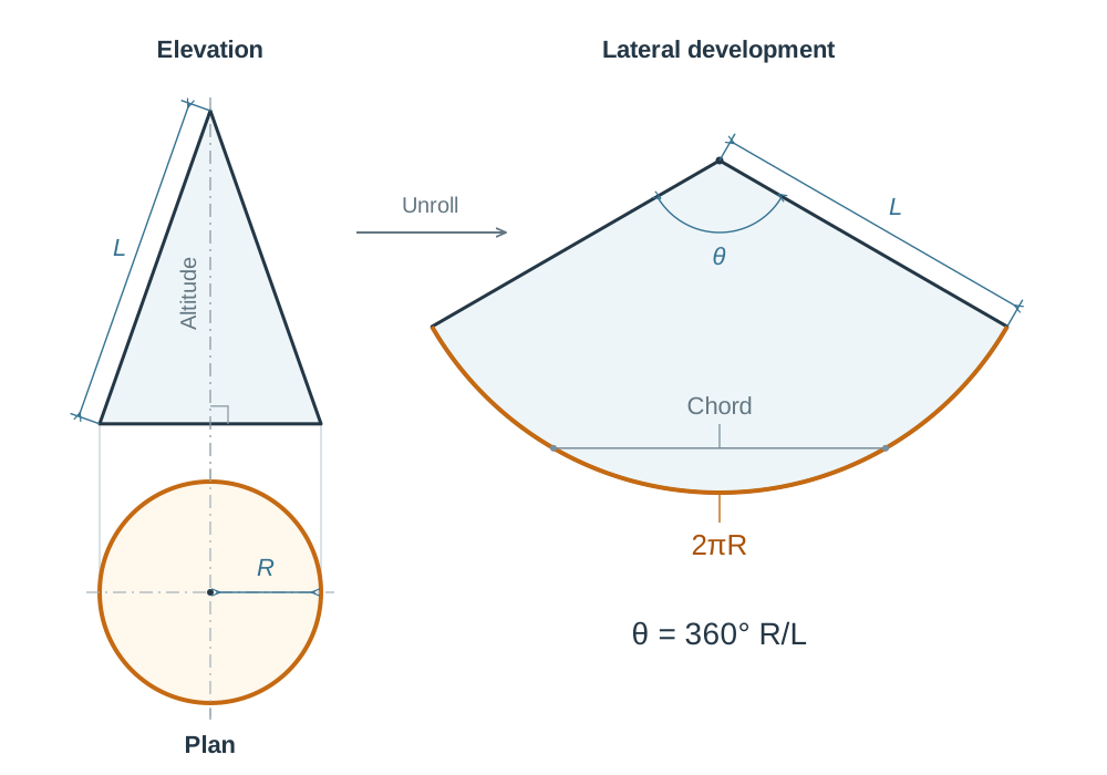
A right circular cone develops into a circular sector of radius , where is the true slant height (the outer silhouette generator in elevation). Unrolled, the base rim becomes an arc of length . A full circle drawn at radius has a circumference of , so the unrolled sector occupies the fraction of a full turn:
You can set out this angle accurately with a protractor, or step 12 chord lengths taken from the plan divisions along the unrolled arc. Setting out the calculated angle is more precise because stepping chords slightly underestimates the true curved circumference.
Truncated Solids: The Silhouette Generator Rule
An internal generator of a cone slopes away from you in elevation, so its length on that view is foreshortened. Never measure cut heights directly off internal generators. Project each cut point horizontally across in elevation onto the outer true-length silhouette generator first. Measure that true distance down from the apex, and swing that specific radius onto the matching generator in your development.
Frustum Given Without an Apex
When an exam question presents a cone or pyramid with its top already sliced away, the apex must be recovered before any arc can be struck. Extend the two sloping outline edges of the frustum upwards in elevation until they intersect. That intersection is the apex . Measure the true slant radius to the base () and the true slant radius to the cut rim () along the outer silhouette generator. From a single centre on your development, strike two concentric arcs of radii and . The area bounded between these two arcs forms the developed lateral sheet.
Lateral vs Complete Development and the Cut Face
Always read the question wording carefully to determine what must be drawn:
- If asked for the lateral surface development or curved surface development, unfold only the wrapping faces. Do not add the base or cut top.
- If asked for the complete surface development, draw the wrapping pattern and hinge both the base and the cut top onto it in their true shape along fold lines.
The base of a solid standing upright on the horizontal plane is seen in its true shape in the plan, so you can trace or transfer it directly.
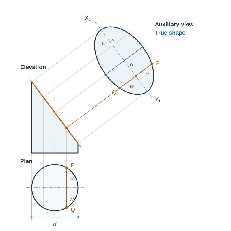
The cut face is inclined to both principal planes, so it appears foreshortened in both plan and elevation. To find its true shape, use auxiliary projection:
- Draw a reference datum line parallel to the inclined cutting-plane line in elevation.
- Project every cut point at right angles () to the cutting plane across your reference line.
- For each point, measure its perpendicular width from the central axis in plan and step that same width onto the auxiliary projector on both sides of the reference line.
- Connect the points: straight lines for a prism or pyramid; a smooth curve for a cylinder or cone.
A plane cutting right across a cylinder gives an ellipse, and so does a plane that cuts every generator of a cone. (A steeper cut on a cone gives a parabola or hyperbola.) For a cylinder, the minor axis of this ellipse must equal the cylinder diameter, providing an immediate check on your accuracy.
Envelopment: Transferring Flat Patterns onto Solids
Envelopment is development run in reverse. When a label, decorative band, or cut-out profile is given on a flat sheet, envelopment transfers those points back onto the orthographic projections of the solid.
Envelopment on a Cylinder
Every point on a cylindrical development is defined by its distance along the stretch-out line and its vertical height:
- On the development, note which numbered generator a point sits on, or measure its offset along the baseline from the nearest generator.
- Step that exact distance around the circular base in plan to locate the point's generator, then project that line into elevation.
- Measure the point's vertical height on the development and mark it on that same generator in elevation.
- Repeat for sufficient points and join them with a smooth curve. Dash any portion passing across the rear half of the cylinder.
Envelopment on a Cone
A point on a conical development is defined by its radial distance from the apex and its angular position:
- Measure the radial distance from apex out to the point on the flat development.
- In elevation, set your compass on apex and swing that distance onto the outer silhouette generator.
- Project horizontally across from the silhouette generator to meet the specific generator the point belongs to. That establishes the point in elevation.
- Project vertically down to the corresponding generator in plan.
A straight band drawn across a flat development curves when wrapped around a cylinder or cone. Conversely, a line that appears straight in elevation curves when unfolded onto the flat pattern.
True Distance Lines and Shortest Surface Paths
Finding the shortest path between two points across the exterior of a solid is a recurring Leaving Certificate problem. The fundamental rule is that the shortest path between two points along any surface is a single straight line on the flat development.
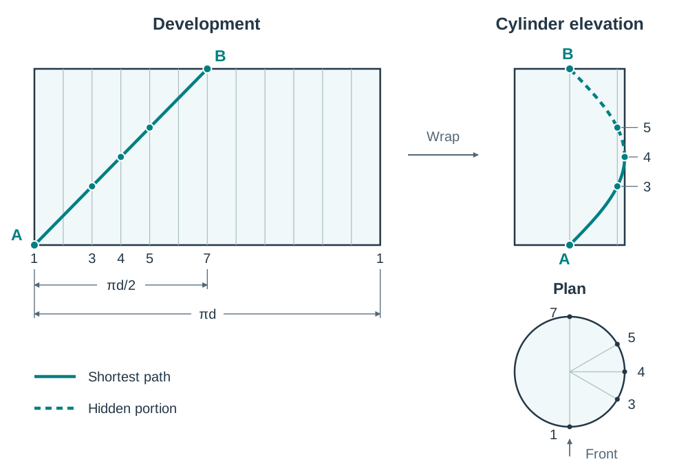
Shortest Path on a Cylinder
- Unroll the curved surface into a rectangle with width equal to .
- Plot starting point and destination point at their known heights and generator stations.
- Connect and with a single straight line across the development.
- Note where this line intersects intermediate generators. Measure their heights and transfer them to the elevation.
- In elevation, join the points with a smooth curve. If the path travels around the rear half of the cylinder, draw that portion as a dashed hidden line.
Shortest Path on a Cone and Pyramid
On a cone, develop the sector, plot and , and connect them with a straight line. Where this line crosses each radial generator, measure the distance from apex , swing that distance back onto the silhouette generator in elevation, and project horizontally across to the target generator. The point where the path passes closest to the apex is found by dropping a perpendicular from apex to line on the development.
On a pyramid, the path crosses flat triangular faces. It is drawn as a straight line on the development, but in plan and elevation it appears as a series of connected straight segments bent at each fold edge, not a continuous curve.
Higher Level: Oblique Pyramids via Triangulation
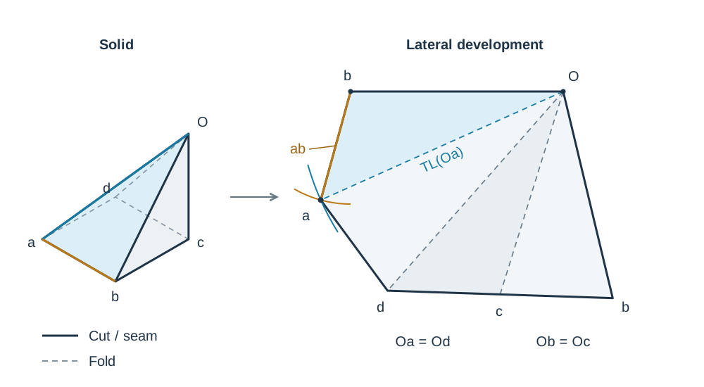
In an oblique pyramid, the apex is not centred over the base, so the lateral edges slant at different angles and each has a different true length. The surface cannot be developed with a single circular arc.
The Triangulation Method
- Number the base vertices in plan and elevation.
- Determine the true length of every slant edge from the apex to each base vertex. In plan, rotate each edge about apex until parallel to the ground line, project vertically to the ground line in elevation, and join to apex . You can check any length using Pythagoras:
where is the plan distance from apex to vertex and is the vertical elevation height.
- Take the true base edge lengths directly from the plan (a horizontal base shows true dimensions in plan).
- Lay down the first triangle on your page, starting along the shortest edge as the seam. From the apex, strike an arc of radius . Strike an intersecting arc from base vertex 1 with radius equal to base length , and a third arc from apex with radius . The intersection fixes vertex 2.
- Construct each adjacent triangular face in sequence until you return to the starting seam. Outline the base with a firm continuous line and internal fold lines with neat dashed lines.
Higher Level: Oblique Prisms via the Right-Section Method
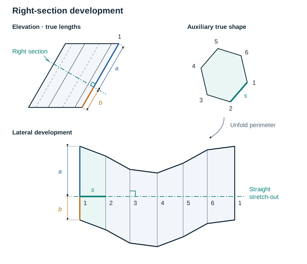
In an oblique prism, the lateral edges are parallel to one another but inclined to the base. If you unroll the solid directly along its base, the pattern does not produce a straight line because the base edges do not meet the lateral edges at right angles. The lateral faces develop as true parallelograms, not rectangles.
The Right-Section Procedure
A right section is an imaginary cutting plane passed strictly perpendicular () to the inclined lateral edges. Because every lateral edge crosses this plane at right angles, the right section unfolds into a perfectly straight stretch-out baseline.
- Position the elevation so the inclined lateral edges are parallel to the vertical plane, displaying their true lengths.
- In elevation, draw a datum line perpendicular () to the lateral edges. This represents the right section.
- Determine the true shape of the right section by projecting an auxiliary view looking parallel to the inclined edges. For a hexagonal prism, this reveals a compressed, non-regular hexagon.
- Draw a straight stretch-out baseline representing the perimeter of the right section. Step off the consecutive edge lengths taken directly from your auxiliary true shape.
- Erect perpendicular generator lines through each station.
- In elevation, measure the distances along each edge above and below the right section line, and transfer those measurements onto the matching perpendiculars on the development.
- Connect the top endpoints and bottom endpoints with firm straight lines to complete the parallelograms.
Developing Solids with an Aperture and Spheres
When one solid penetrates another, the flat pattern of the pierced solid must show the aperture (hole) that has to be cut out.
Apertures from Interpenetrating Solids
- Number the generators or edges of both solids (1 to 12 for curved surfaces) and locate the points of interpenetration in plan and elevation.
- Develop the pierced solid using its standard method (parallel-line or radial-line).
- Transfer each interpenetration point onto its matching generator on the development. For a cylinder or prism, transfer the vertical height from elevation. For a cone or pyramid, project the point horizontally to the silhouette generator first to find its true distance from the apex.
- Connect the points with a smooth curve or straight segments. The aperture outline is a cut edge, so draw it firm and continuous.
Approximate Development of a Sphere
A sphere has double curvature and cannot be flattened without stretching or tearing. It is developed approximately using two methods:
- Zone (Frustum) Method: The sphere is sliced by horizontal planes into horizontal bands (zones). In elevation, each zone chord is extended to intersect the central axis, establishing the apex of a cone that approximates that zone. Each zone is developed as a conical frustum.
- Lune (Gore) Method: The sphere is cut by vertical meridian planes passing through the poles into equal gores, resembling football panels. The vertical stretch-out length of one gore equals half the great-circle circumference. The gore widths are stepped symmetrically from the centre line using chord widths taken from the plan.
Composite Solids and Transition Pieces
A composite solid consists of two or more distinct geometric forms joined together along a shared seam, such as a cylinder connected to a conical reducer. These forms feature prominently when you analyse the underlying geometry of kettle bodies and spouts for the 2027 Student Assignment brief.
Checking the Shared Junction
When developing composite solids:
- Develop each component independently using its own method (parallel-line for the cylindrical portion, radial-line for the conical portion).
- Keep generator numbering consistent across the interface (generator 3 of the cylinder must align with generator 3 of the cone).
- Always check the shared dimension across the joint: the developed length of the cylinder rim () must match the unrolled arc length of the cone frustum at that same junction diameter. If they do not match, recheck your division stepping.
Transition Pieces (Surface Geometry Option)
Transition pieces connect duct openings of different cross-sections, such as a square ventilation duct connecting to a circular pipe. Each corner forms a partial oblique cone, while the flat sides form plane triangles. The circular opening is divided into 12 parts, joined back to the square corners, and every seam line is found at its true length by triangulation before laying out the pattern panels in sequence.
Key terms
- Surface Development
- The complete unfolding of all exterior surfaces of a 3D solid onto a single flat 2D plane so that every line is a true length and every face is a true shape.
- Envelopment
- The process of wrapping, folding, or transferring a flat 2D pattern, label, or profile around a 3D solid.
- True Length (TL)
- The actual physical length of a line in 3D space, visible in an orthographic view only when the line is parallel to that plane of projection.
- True Shape (TS)
- The undistorted, actual profile and dimensions of a surface, visible only when looking perpendicular to the plane containing that surface.
- Generator
- An imaginary straight line lying on a curved surface (such as a cylinder or cone) connecting boundary rims or converging at an apex, used to divide surfaces for projection.
- Stretch-Out Line
- A straight baseline representing the unfolded perimeter or circumference of a prism, cylinder, or right section along which face widths are stepped.
- Right Section
- A transverse cutting plane passed perpendicular to the inclined lateral edges or generators of an oblique prism or cylinder, used to create a straight stretch-out baseline.
- Triangulation
- A development method that divides an irregular or oblique surface into a series of adjoining triangles, constructed sequentially from known true edge lengths.
- Frustum
- The lower portion of a pyramid or cone remaining after the top portion containing the apex has been sliced off by a plane parallel to the base.
- True Distance Line
- The shortest path between two points travelling strictly along the surface of a solid, which plots as a single straight line on the flat development.
- Parallel-Line Development
- A development method used for prisms and cylinders where all edges or generators are parallel to one another.
- Radial-Line Development
- A development method used for right cones and pyramids where all edges or generators radiate from a single shared apex.
Check yourself
What is the sector angle for the lateral surface development of a right cone with base diameter 50 mm and true slant height 100 mm?
90 degrees. Base radius and slant height . Applying the sector formula: .
A cone has a base radius of 30 mm and a true slant height of 85 mm. An inclined cut crosses generator 5 at a point which, projected horizontally onto the silhouette generator, lies 52 mm from the apex. How far from the apex do you mark that point on generator 5 on the development, and why?
52 mm. The outer silhouette generator is a true length, and on a radial development, the radial distance from the apex along any generator is always the true distance measured from the apex.
Why does a right-section line need to be constructed when developing an oblique prism?
Because the base edges of an oblique prism do not meet the lateral edges at 90 degrees, the base does not unroll into a straight line. A section cut perpendicular to the lateral edges meets all faces at 90 degrees, unrolling into a straight stretch-out baseline.
How do you recover the apex when given only the orthographic elevation of a frustum of a cone?
In elevation, extend the two sloping outline silhouette edges upwards until they intersect. That intersection point is the apex from which all true slant radii are measured.
How does a straight shortest-distance line drawn on a cylindrical development appear when wrapped back onto the cylinder in elevation?
It wraps around the curved surface to form a 3D helix, which projects as a smooth orthographic curve in elevation.