
A tetrahedron is a pyramid with a triangular base. In a regular tetrahedron all four faces are identical equilateral triangles, so the solid looks the same whichever face it rests on. In Leaving Certificate Design and Communication Graphics at Higher Level, it is a core solid across Projection Systems and Descriptive Geometry. Mastering this topic requires being able to construct it in standard, inclined, and oblique positions, find its true vertical height graphically, locate its common incentre and circumcentre, draw its inscribed and circumscribed spheres, determine the dihedral angle between adjacent faces, and solve sections and developments.
Geometry, Key Dimensions, and Orientation Guide
A regular tetrahedron has four identical equilateral triangular faces, four vertices, and six equal edges. Because every edge has the same length , its key dimensions can all be calculated from or derived by direct construction.
The Three Key Heights
Do not confuse the three different slant and vertical measurements of a regular tetrahedron of edge length :
- Face Altitude (): The altitude or median of one equilateral face, from a vertex to the midpoint of the opposite edge:
- Plan Radius: The distance in plan from the centroid of the base triangle out to any base corner. Because the apex sits directly over this centroid, this is also the plan length of each slant edge:
- True Vertical Height (): The perpendicular height from the base face to the apex. In the internal right-angled triangle formed by the slant edge (hypotenuse ), the plan radius, and the vertical height:
Orientation Decision Guide
Exam questions set the tetrahedron in several standard orientations. Before drawing a single line, check how the solid is positioned:
- Face on the HP: Draw the base as a true equilateral triangle in plan, then find apex height in elevation using a true-length arc.
- A face or edge inclined to the HP: Draw the solid in the simple position (face on the HP) first, then tilt it in a second elevation and reproject the plan.
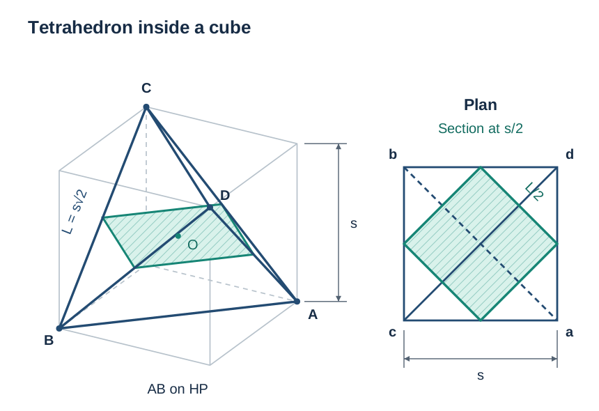
- Two opposite edges horizontal (cube orientation): The plan is a square of side with both diagonals drawn at true length . The vertical distance between the two horizontal edges is , not .
- Projections already given in an oblique position: Find true lengths using an auxiliary view set parallel to an edge, or find the centre directly using the 3:1 median rule without needing any auxiliary view.
Standard Projections, Height Derivation, and Tilting
Constructing the Solid Resting on Face ABC
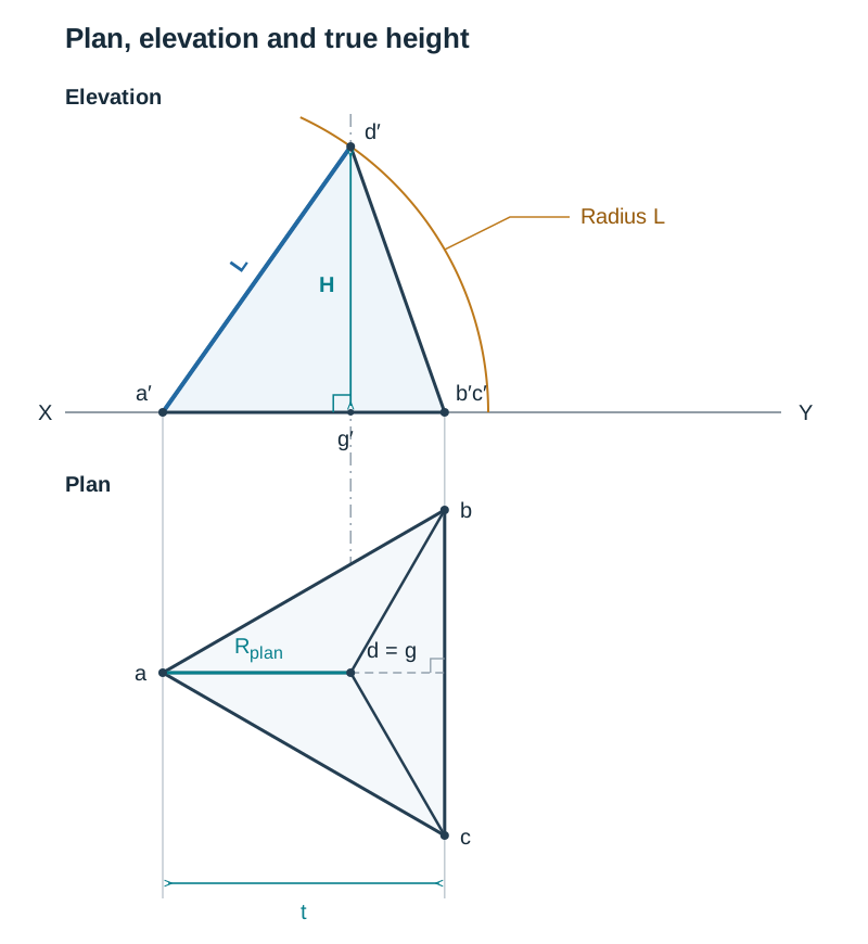
To make the drawing straightforward, position base edge perpendicular to the line in plan. This aligns edge parallel to the vertical plane, so it projects as a true length in elevation.
- Plan view: Draw the base equilateral triangle of side with edge perpendicular to . Bisect two corners to find centroid . Connect to , , and . The plan of apex coincides with .
- Elevation baseline: Project and up to . Because is perpendicular to the vertical plane, both points meet at . Project up to to give . The line is the edge view of the base face.
- Apex height by construction: Project a vertical centreline upward from in plan. Because is parallel to , slant edge is parallel to the VP and appears at true length in elevation. Put the compass point on on the line, open it to the edge length , and swing an arc cutting the centreline at .
- Complete the elevation: Join to and to . The line shows face as an edge view.
Note on projection angle: Higher Level candidates must also be familiar with third-angle projection. In third angle, the plan is placed above and the elevation below, but all construction arcs and height relationships remain identical.
Tilting the Solid: The Two-Stage Method
When face is inclined at an angle (such as 35°) to the horizontal plane, you cannot draw the tilted solid directly. Always construct it in the simple position first, then move it:
- Stage 1 (simple position): Draw the plan and elevation with face on the HP and edge perpendicular to , as described above.
- Stage 2 (tilt in elevation): Redraw the elevation outline with the base line rotated to the required angle (e.g. 35°) to , pivoting about . Because tilting about an axis perpendicular to the VP preserves all front-view shapes, the second elevation is an identical copy of the first, simply rotated.
- Stage 3 (reproject the plan): Drop vertical projectors from each vertex of the tilted elevation. Each point keeps the exact same distance behind that it had in the Stage 1 plan. Transfer those distances with dividers onto the new projectors and join the vertices to finish the plan.
Useful reference angles from the simple elevation:
- A slant edge makes with the base plane: .
- Any face makes with the base plane, which equals the dihedral angle between any two faces.
Incentre, Circumcentre, and Spheres
Because a regular tetrahedron is completely symmetrical, the centre of the inscribed sphere (the incentre) and the centre of the circumscribed sphere (the circumcentre) are the exact same point on the central axis.
The 1:3 Height Division
The centre divides the perpendicular vertical height along the axis in a ratio:
- Inscribed sphere (insphere): Sits inside the tetrahedron, tangent to all four faces at their centroids. Radius .
- Circumscribed sphere (circumsphere): Encloses the tetrahedron, passing through all four vertices . Radius .
- Key relationships: and .
Graphical Construction in Elevation
With edge perpendicular to in plan:
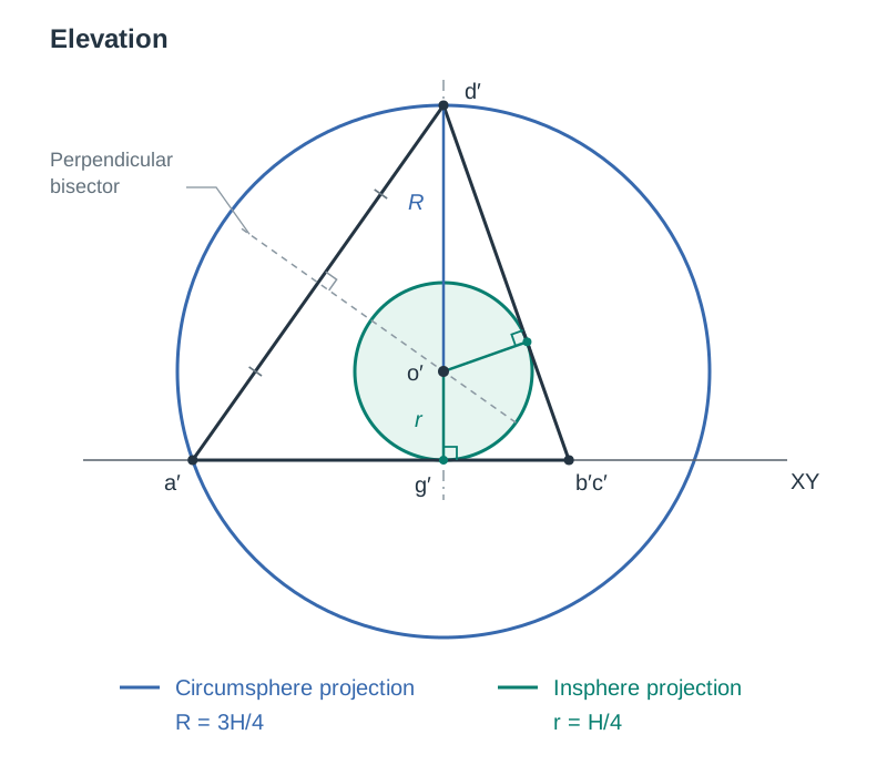
- Draw the vertical axis line from apex down to centroid on .
- Locate circumcentre : Construct the perpendicular bisector of the true length edge . Where it crosses the vertical axis line is centre .
- Check with incentre: Bisect the angle at between (edge view of face ) and line (edge view of face ). This bisector cuts the axis at the same point .
- Insphere contact point: Drop a perpendicular from to line . This gives the exact point of contact on that face.
- Draw spheres: In elevation, draw the insphere with radius and the circumsphere with radius .
Tangency Checks
In elevation, the insphere circle touches only the lines that are edge views of faces: and . It does not touch , which is an individual edge, not a face seen on edge. In plan, the circumsphere circle sits outside the base vertices , because each vertex is from the centre in plan, while the true sphere radius is larger ().
Finding the Centre in an Oblique View
If the tetrahedron is presented in an oblique position with no true-length view, you can still find centre without drawing an auxiliary view, because parallel projection preserves ratios along lines:
- Method 1 (3:1 ratio): In plan, join vertex to the centroid of the opposite face . Point lies one quarter of the way along this line from the face centroid towards . Repeat in elevation for .
- Method 2 (opposite edge midpoints): Find the midpoint of edge and the midpoint of the opposite edge . Join them with a line. Centre is the exact midpoint of that connecting line in both plan and elevation.
Descriptive Geometry: Dihedral Angle and Reverse Construction
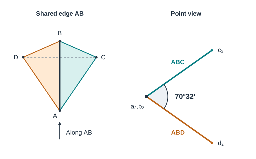
The dihedral angle is the true angle between two intersecting planes. To see it at its true size, you must obtain a point view of the shared edge. In that view, both faces appear as straight lines (edge views).
For any regular tetrahedron, the dihedral angle between any two faces is:
Two-Auxiliary Projection Method
To determine the dihedral angle between faces and sharing edge :
- First auxiliary view (true length): Draw ground line parallel to plan line . Project all four vertices perpendicular to . Transfer vertical heights from the elevation (measured above ) onto the corresponding projectors. Edge is now shown at true length.
- Second auxiliary view (point view): Draw ground line perpendicular to true length . Project all vertices parallel to (perpendicular to ). Transfer perpendicular distances from back into the plan view. Vertices and merge into a single point view , while faces and appear as two lines.
- Read the angle: Measure the angle between the two lines with a protractor. It will read .
Reverse Construction: Completing the Solid from One Oblique Edge AB
- Set parallel to and project the true length .
- Set perpendicular to to project the point view .
- In this second auxiliary view, draw the two faces radiating from at to each other. Vertices and lie at distance from .
- Project points and back to the first auxiliary view, then perpendicular to back to plan, and transfer heights back to elevation.
Sections, Cube Relationship, and Surface Development
Sections by Simply Inclined Planes
A plane perpendicular to the VP appears as a single edge-view line in elevation. To draw the section and find its true shape:
- In elevation, identify where the cutting line crosses each edge of the solid. Label these cut points , etc.
- Project each point vertically down onto the corresponding edge in plan. A point on an outline that represents two superimposed edges (such as ) yields two separate points in plan.
- Join the plan cut points in sequence and add hatching.
- True shape: Set up an auxiliary ground line parallel to the cutting plane line in elevation. Project each cut point perpendicular to , and transfer its plan distance from onto its projector. Join the points to complete the true shape.
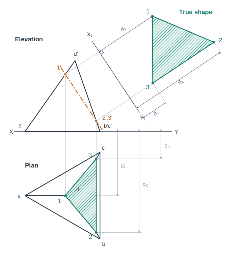
Cut profiles: Slicing three edges gives a triangular section; slicing four edges gives a quadrilateral. If a plane is parallel to two opposite edges, it cuts a rectangle. Halfway between those two edges, that rectangle becomes a square of side .
Opposite Edges Horizontal (Cube Relationship)
A regular tetrahedron can be inscribed in a cube of side by joining alternating corners. The tetrahedron edges are the face diagonals of the cube, so , giving .
When a tetrahedron rests with edge on the HP and opposite edge horizontal:
- The plan is a square of side , with both diagonals showing true lengths .
- The total vertical height between the two edges is (not ).
- Centre sits halfway up at height .
- A horizontal cutting plane at height produces a square section of side .
Surface Development
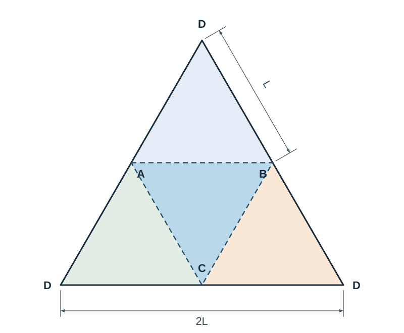
Because all four faces are identical equilateral triangles of side , the development is drawn without hunting for true lengths: construct one base equilateral triangle of side , then draw an identical equilateral triangle on each of its three outer edges. The result is one large equilateral triangle of side , divided into four.
To develop a cut solid, measure the true distance of each cut point from a vertex along its edge (taken from a view showing that edge at true length), step it off along the corresponding edge on the development, and join the points.
Leaving Certificate Examination Structure (2027 Arrangements)
Leaving Certificate Design and Communication Graphics is assessed through two components:
- Student Assignment (40%): A design investigation, freehand sketches, and SolidWorks CAD portfolio (maximum 10 pages at Higher Level).
- Terminal Written Examination (60%): A 3-hour written examination (240 marks total).
Under the 2027 assessment arrangements, the Higher Level written paper structure is:
- Section A (Core): Four questions, answer any three (20 marks each; 60 marks total).
- Section B (Core): Three questions, answer any two (60 marks each; 120 marks total).
- Section C (Options): Five questions, answer any one from the options studied (60 marks).
Both Section A and Section B draw on all core areas. A tetrahedron question is usually a 20-mark Section A problem (such as finding true height, locating the centre, or drawing spheres) or forms part of a 60-mark Section B descriptive geometry question. Budget approximately 12 to 15 minutes for a Section A tetrahedron problem.
Key terms
- Regular Tetrahedron
- A regular polyhedron bounded by four congruent equilateral triangular faces, four vertices, and six equal edges.
- Centroid
- The geometric centre of an equilateral triangle, located where its medians intersect, two-thirds of the distance from any vertex to the opposite side.
- True Length
- The actual spatial length of a line, seen in orthographic projection only when the line is parallel to the plane of projection.
- Point View
- An orthographic view obtained by looking directly along the true length of a line, causing the entire line segment to project as a single point.
- Edge View
- An orthographic projection in which an entire flat surface projects as a single straight line, obtained by looking along a true-length line lying on that surface.
- Dihedral Angle
- The true internal angle between two intersecting planes, measured in a view where their common line of intersection appears as a point view.
- Incentre
- The centre of the inscribed sphere, located on the vertical axis at one-quarter of the total height (H/4) above the base face.
- Circumcentre
- The centre of the circumscribed sphere passing through all four vertices, which coincides with the incentre on the vertical axis.
- Inscribed Sphere
- A sphere completely contained inside the tetrahedron that touches each of the four triangular faces tangentially at its centroid.
- Circumscribed Sphere
- A sphere that completely encloses the tetrahedron such that all four vertices lie on its spherical surface.
- First Auxiliary View
- A projection onto a new reference plane (X1Y1) perpendicular to one of the principal planes, used to find the true length of an inclined line or edge view of a plane.
- X1Y1 / X2Y2
- Reference ground lines representing the edge views of successive auxiliary projection planes used in descriptive geometry.
Check yourself
A regular tetrahedron has an edge length of 90 mm and rests with one face on the HP. Calculate its vertical height H, inradius r, and circumradius R.
H = 90 * sqrt(2/3) ≈ 73.5 mm; r = H / 4 ≈ 18.4 mm; R = 3H / 4 ≈ 55.1 mm.
What is the true dihedral angle between any two adjacent faces of a regular tetrahedron?
Approximately 70° 32' (70.53°), derived from cos θ = 1/3.
What orientation in plan ensures slant edge DA appears at true length in elevation?
Placing base edge BC perpendicular to the XY line, which makes the plan of median/edge DA parallel to the XY line (and therefore parallel to the VP).
How can you find the centre O of a tetrahedron in an oblique plan and elevation without using an auxiliary view?
Find the midpoints of two mutually opposite edges and join them; centre O is the exact midpoint of that connecting line in both plan and elevation.
When a regular tetrahedron of edge L rests with two opposite edges horizontal, what is its vertical separation and plan outline?
Vertical separation is the circumscribed cube side s = L / sqrt(2) ≈ 0.707L, and the plan outline is a square of side s with both diagonals drawn at true length L.