
Surface Geometry investigates the relationships, lines of intersection, and flat-pattern developments of three-dimensional surfaces found in sheet-metal fabrications, packaging, ductwork, and architectural roof systems. For Leaving Certificate Higher Level Design & Communication Graphics (Section C, Option 4), you must master determining dihedral angles between planar surfaces, constructing lines of intersection between right and oblique solids, developing containers and intersecting ductwork (including oblique prisms and cylinders), and developing transition pieces connecting rectilinear-to-rectilinear, circular-to-circular, and circular-to-rectilinear duct profiles. Every flat development must be constructed exclusively from true lengths and true shapes. Under the 2027 assessment arrangements, Section C offers five questions from which you answer any one 60-mark question, representing approximately 45 minutes of drawing time.
Foundational Principles: True Lengths and True Shapes
A surface development represents the unrolling or unfolding of a 3D solid onto a single two-dimensional flat plane. For the template to assemble correctly in sheet-metal fabrication, every edge, generator, and face must be laid out in its true size.
An edge or element line appears at its true length (TL) only when the line of sight is perpendicular to it, meaning the line itself is parallel to that projection plane:
- A horizontal line appears at true length in the plan view.
- A line parallel to the vertical plane appears at true length in the elevation.
- Any oblique line appears foreshortened in standard views and requires a geometric construction.
You have two primary methods to determine true lengths:
Right-Angled Triangle Construction
Construct a right-angled triangle where the base equals the horizontal plan length () of the line, and the vertical upright equals the difference in elevation () between its two endpoints. The hypotenuse represents the true length:
For example, if an edge has a plan length of 45 mm and rises 60 mm in elevation, its true length is . Construct this directly on your sheet using compasses or set-squares to find the hypotenuse without calculation.
Auxiliary Projection Method
Set up a new datum ground line () parallel to the view of the line in plan. Projecting perpendicular to and transferring vertical heights from the elevation yields the true length in the auxiliary elevation.
Establishing True Shapes
A plane surface appears in true shape when your line of sight is at right angles to the surface itself. In practice you get there in two steps: first obtain an edge view, in which the plane appears as a single line (project along a true length line lying on the plane, so that line becomes a point); then draw a new reference line parallel to that edge view line and project a further auxiliary view at right angles to . That view is the true shape. Alternatively, use rebatment (rotating the face flat about an edge) or triangulation.
Determining Dihedral Angles
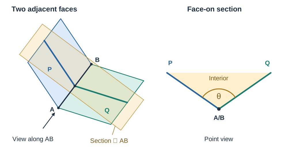
A dihedral angle is the true internal angle formed between two intersecting plane surfaces. It must be measured on a cutting plane positioned strictly perpendicular to their common line of intersection.
How Many Auxiliary Views Are Needed?
The number of auxiliary views depends entirely on how the line of intersection lies:
- Common edge vertical: Both surfaces are vertical planes, so they already appear as lines in plan. The dihedral angle can be measured directly in plan without any auxiliary view.
- Common edge horizontal: A horizontal line is already at true length in plan. Set one reference line perpendicular to it in plan and project a single auxiliary elevation. The edge becomes a point view and both faces become edge views: one auxiliary view only.
- Common edge oblique: When the edge slopes in both views, two auxiliary views are necessary: the first to obtain its true length, and the second to see it as a point.
The Point View Method (Two Auxiliaries)
- Identify the Line of Intersection: Find the common edge shared by both planar surfaces in plan and elevation.
- Auxiliary View 1 (True Length): Set up a datum line parallel to the line of intersection in plan. Project all vertices of both faces perpendicular to . Transfer vertical heights from the elevation (measuring from the original ground line). In this view, the shared edge appears at its true length ().
- Auxiliary View 2 (Point View): Set up a second datum line strictly perpendicular to the true length line . Project all points parallel to through . Transfer perpendicular distances taken from the line back into the plan view.
- Measure the Angle: Because both endpoints of the intersection line lie at equal perpendicular distances from in plan, they merge into a single point view . Both planar faces project as single lines (edge views). In the point view the two edge views form two angles that add to . The dihedral angle asked for is the one that lies inside the object, through the material. If you measure the outside acute supplement by mistake, subtract it from .
Rebatment Method
Pass a cutting plane perpendicular to the true length of the intersection line. This slices a triangular section from the two surfaces. Rebate (rotate) this triangle flat about its base into a principal projection plane to read the angle directly at the rebated vertex.
Intersecting Roof Surfaces: Hips, Valleys, and Ridges
Architectural roof systems consist of intersecting planar surfaces meeting along ridges (horizontal top edges), hip lines (external sloping edges), and valley lines (internal sloping drainage gutters).
Geometry of Equal-Pitch Roofs
When intersecting roof surfaces possess the same slope or pitch:
- Each hip or valley line in plan bisects the angle formed between the adjoining eaves lines.
- On a rectangular building with horizontal eaves meeting at , the plan of each hip line runs at exactly until it strikes the ridge line.
- The ridge line is horizontal, meaning all points along it share an identical vertical height.
Roofs of Unequal Pitch
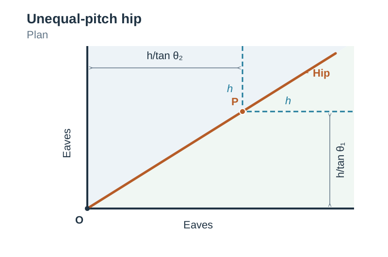
The angle-bisector rule applies only when the two roof surfaces have the same pitch. If the pitches differ, the hip swings towards the steeper slope and must be constructed using level lines (contours):
- Choose a convenient height above the eaves.
- For each roof surface, calculate the horizontal distance back from its eaves to the contour line at height : , where is the pitch angle of that surface.
- In plan, draw each level line parallel to its eaves at its own horizontal distance.
- The two level lines intersect at a point that is at height on both surfaces, placing it on the line of intersection.
- Join this intersection point to the eaves corner to establish the plan direction of the hip or valley, and extend it to intersect the ridge.
Roof True Shapes and Hip Dihedral Angles
To find the true shape of a roof panel, rebate it about its horizontal eaves line using the true pitch length (found from an auxiliary view or end elevation). To find the hip dihedral angle, use the point view method along the hip line.
Surface Developments: Right Solids, Cones, and Hoppers
A surface development unfolds all boundary surfaces of a 3D solid into a single continuous template. Cut boundaries are drawn as firm solid lines, while fold lines are drawn with thin dashed lines.
Development Methods by Surface Type
| Surface Geometry | Development Method | Construction Control |
|---|---|---|
| Right Prisms | Parallel-Line | Stretch-out line = perimeter; edges perpendicular |
| Right Cylinders | Parallel-Line | Stretch-out line = ; generators spaced equally |
| Right Pyramids | Triangulation / True Shapes | True slant edges and base edges form triangles |
| Right Cones | Radial-Line | True slant height ; sector angle |
| Oblique Prisms & Cylinders | Right-Section Method | Stretch-out line = stepped chord perimeter of right section |
| Oblique Cones & Pyramids | Radial Triangulation | Independent true length for every generator/edge |
| Transition Pieces | Triangulation | True lengths of corner elements and boundary chords |
Right Cylinders and Truncated Right Cones
- Right Cylinder: The stretch-out line equals the circumference . Divide the plan circle into 12 equal spaces ( increments). Transfer generator heights from elevation perpendicular to the stretch-out line.
- Right Cone Sector Angle: For a cone with base radius and true slant height , the subtended sector angle is .
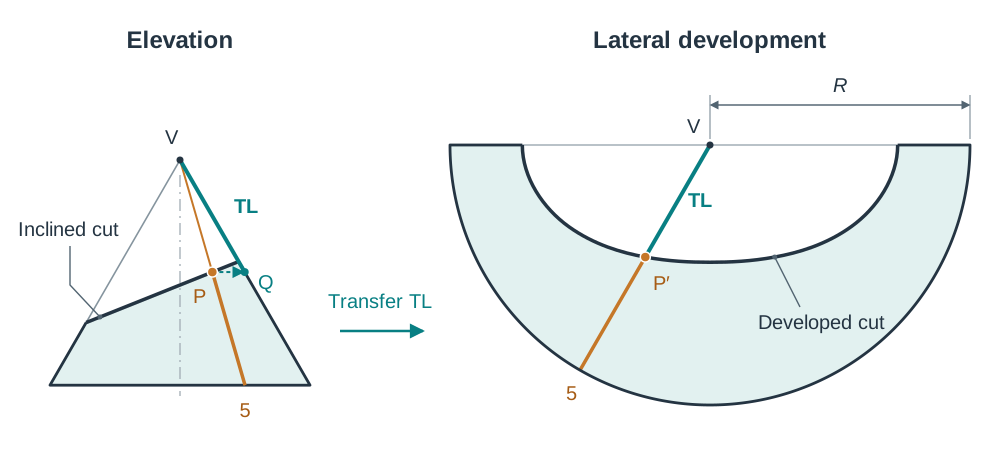
- Truncated Cut Cones: When an inclined plane cuts across a right cone, only the extreme outline generators show true lengths in elevation. For any intermediate generator, project the cut point horizontally across onto an outside outline generator. The reason for projecting horizontally to the outline generator is that swinging a point horizontally about the vertical axis of the cone does not change its height or its distance from the apex, so its true distance from the apex can be read directly off the outline generator. Swing that radius onto the corresponding numbered generator in the development sector.
Oblique Cones and Oblique Pyramids: Radial Triangulation
In an oblique (scalene) cone, every generator has a different length, so you cannot use a single circular sector arc. Instead, build the pattern triangle by triangle:
- In plan, divide the base circle into 12 equal parts and join each point to the apex.
- Construct one true length diagram, placed clear of the views: erect a vertical line equal to the cone height, and along its horizontal base set off each plan generator length. The hypotenuse gives the true length of each generator.
- The chord between adjacent circle points in plan is already a true length because both points lie in the same horizontal base plane.
- Start on the shortest generator (the seam). Draw it to true length. From the apex, strike an arc equal to the true length of the next generator; from the base point, strike an arc equal to the base chord. Their intersection locates the next rim point. Repeat around the solid.
Transferring Features and Shortest Paths
A development is a true-size flat pattern, so any point on it is fixed by two true distances measured on the surface: measure along a fold line or generator, never across open space.
- From views to development: Number every generator 1 to 12 and letter every corner A to D across all views. Measure the true distance of the feature along its generator or from a known corner, then set that distance along the matching generator on the development.
- From development back to views: Mark where the feature crosses fold lines or generators on the development. Measure the true distance of each crossing from a corner, set it off along the corresponding edge in the orthographic views, and project between plan and elevation.
- Shortest Path: The shortest path between two points across adjacent faces of a solid is a single straight line drawn on the surface development. Develop the relevant surfaces joined along their common fold line, connect the start and end points with a straight line, mark where this line crosses the shared fold line, and project the crossover points back into the plan and elevation views.
Intersecting Ductwork: Right and Oblique Solids
Intersecting ductwork requires you to establish the line of intersection before either flat pattern can be unrolled. Every point on a line of intersection must lie on both surfaces simultaneously.
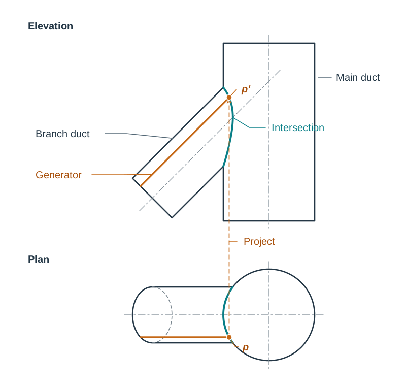
Locating the Line of Intersection
- Generator Line Method: Divide curved surfaces into 12 equal elements in plan or an end view. Trace where each generator pierces the surface of the adjoining duct, and project these points across to the corresponding elevation generators.
- Cutting Plane Method: Pass a series of parallel cutting planes through both solids. Each plane slices lines from prisms or circles/lines from cylinders. The points where the cut profiles intersect identify shared points on the seam.
- Critical Points: Always identify the extreme turning points (maxima, minima, and tangency points) where curves reverse or change visibility from solid to hidden detail.
Developing Oblique Prisms and Oblique Cylinders (Higher Level Only)
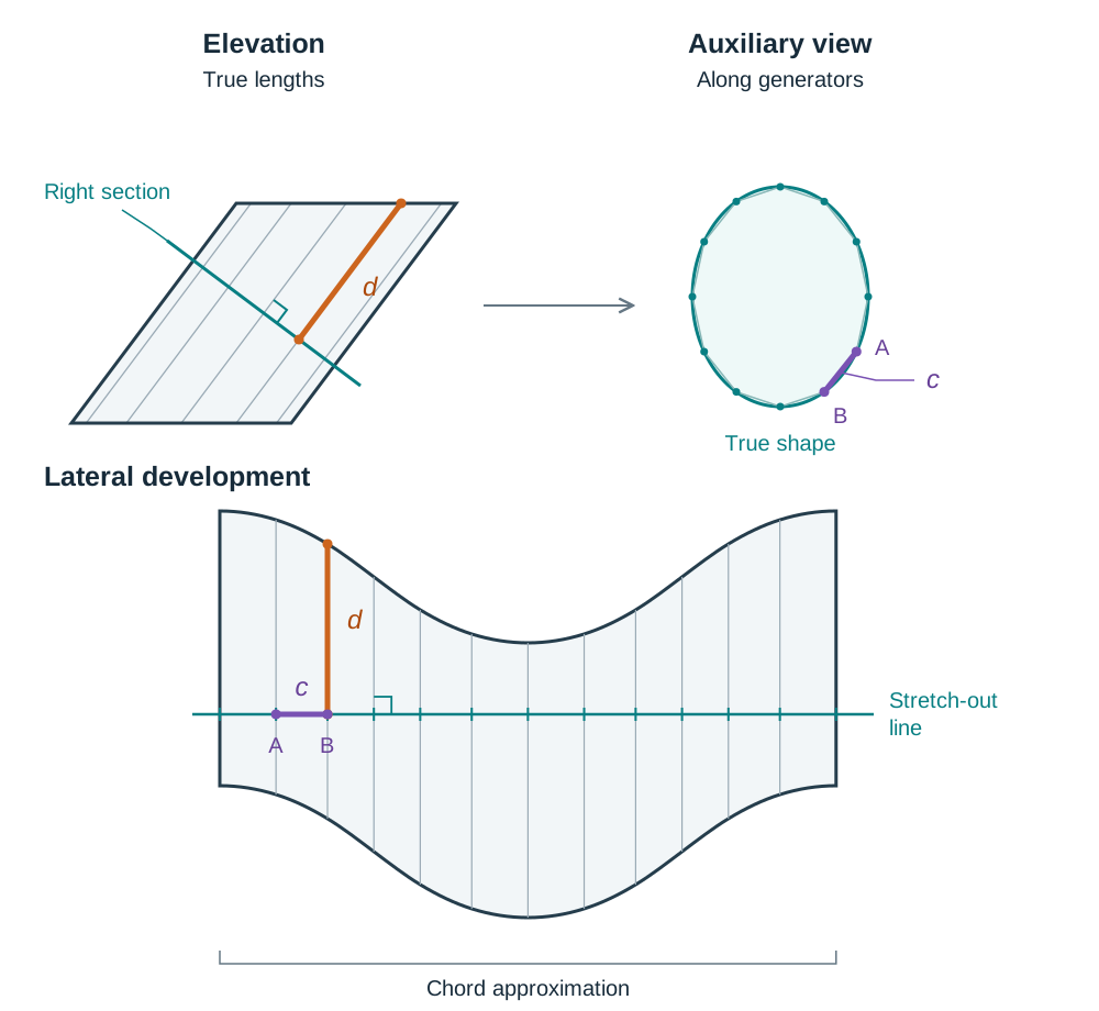
In an oblique prism or cylinder, the generators are parallel to one another but inclined to the base. Because the end profiles do not lie perpendicular to the generators, you cannot unroll the development along the base edge.
Instead, use the right-section method:
- Draw the elevation view such that the generators lie parallel to the vertical plane, displaying their true length.
- Pass a cutting plane perpendicular to the generators across the solid to establish a right section.
- Construct an auxiliary view looking along the generators to determine the true shape of this right section. For an oblique cylinder with circular ends, the right section is an ellipse.
- Divide the true shape of the right section into 12 equal parts. Set out a straight stretch-out line and step off along it, one after another with your compasses, the 12 chord distances taken from that true shape. Do not attempt to calculate the perimeter of the ellipse: its length is the sum of the 12 chords stepped off.
- Project generator lines perpendicular to the stretch-out line.
- From the elevation, transfer the true distances measured along each generator from the right section up to the top rim, down to the base, and to any intersection points.
- Connect the plotted endpoints with a smooth continuous curve for cylinders, or with straight fold lines for prisms.
Transition Pieces and Triangulation
A transition piece is a sheet-metal connector that joins ducts of differing shapes, sizes, or alignments (such as a round duct to a rectangular trunking). Because transition surfaces are compound and non-parallel, they must be unrolled using triangulation.
Triangulation Categories
- Rectilinear to Rectilinear: Both ends are polygons. Connect corresponding corners with diagonal fold lines to divide each four-sided face into two flat triangles. Construct true lengths of edges and diagonals using right-angled triangles, then build the pattern triangle by triangle.
- Circular to Circular: When two circular ducts are parallel and aligned on a common central axis, the transition forms a right conical frustum developed via radial lines. If the circular ends are eccentric (off-centre) or inclined, divide both circles into 12 equal parts, connect corresponding points to create a web of triangles, find all true lengths, and develop sequentially.
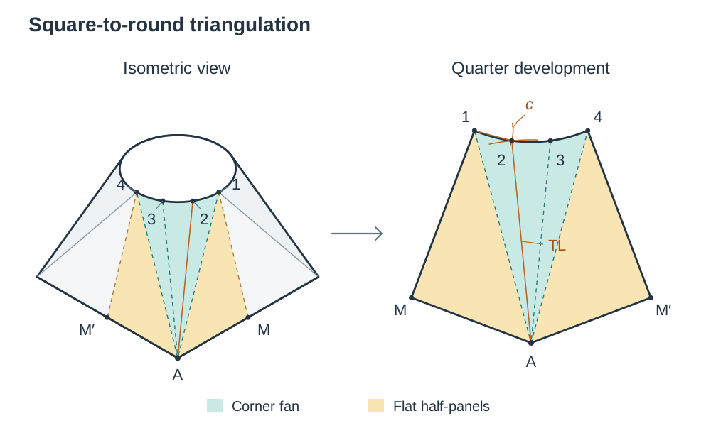
- Circular to Rectilinear (Higher Level Only): A square-to-round or rectangular-to-round connector consists of four flat triangular panels located above the sides of the rectilinear opening, combined with four curved conical corner 'fans' positioned at each corner.
Systematic Triangulation Procedure for Circular-to-Rectilinear Pieces
- Divide the circle into 12 equal sectors ( intervals) in plan, numbered to . Label rectilinear base corners .
- Connect each corner to its adjacent circle points (for example, corner connects to points ).
- Construct one true length diagram, placed clear of the views. Draw a vertical line representing the constant elevation height difference (). Along a perpendicular horizontal baseline, step off each horizontal plan length (). The hypotenuse represents the true length of that surface element.
- Determine the rim spacing: both points lie on the same horizontal circle, so they are at the same height. A line joining them is horizontal, and a horizontal line is already true length in plan, so take the chord straight from the plan with your compasses (). This is standard manual draughting practice.
- Locate the seam along the shortest element (typically the line of symmetry at the centre of a flat side). Construct the first triangle using the known base width and two true lengths.
- Attach subsequent corner fan triangles by swinging arcs using the true element lengths from the corner vertex and the chord lengths () between circle points.
- Finish by drawing a smooth, fair curve through the circular top points and firm, straight lines between the base corners.
Key terms
- Dihedral Angle
- The true internal angle between two intersecting plane surfaces, measured on a plane strictly perpendicular to their common line of intersection.
- Line of Intersection
- The shared straight line or continuous curve where two surfaces meet and penetrate each other.
- True Length
- The actual physical length of a line in space, visible in orthographic projection only when the line of sight is perpendicular to it (the line is parallel to the projection plane).
- True Shape
- The undistorted flat geometry of a plane face, obtained by looking perpendicularly at an edge view of that plane.
- Point View
- A projection obtained by looking directly along the true length of a straight line, causing the line to collapse into a single point.
- Edge View
- A projection in which a planar surface appears as a single straight line because the viewing direction is parallel to the plane.
- Surface Development
- A two-dimensional flat pattern of all exterior faces of a 3D solid that can be cut and folded to form the original object.
- Envelopment
- The reverse operation of development, in which a flat sheet pattern is folded or wrapped to construct the 3D solid.
- Generator
- A straight surface line on a ruled form (such as a cylinder or cone) connecting boundary rims or passing through the apex.
- Right Section
- A cross-section sliced strictly perpendicular to the axis or generators of a prism or cylinder, providing the true transverse spacing for development.
- Stretch-out Line
- The straight baseline of a parallel-line development, equal in length to the true perimeter of the right section or base, along which generator spacings are stepped off.
- Transition Piece
- A ducting connector engineered to join openings of differing cross-sectional shapes, sizes, or orientations.
- Triangulation
- A development method that subdivides complex, non-parallel, or curved surfaces into adjacent planar triangles determined by true edge lengths.
- Rebatment
- The geometric rotation of an inclined plane or section about a hinge line into or parallel to a principal plane of projection to determine its true shape.
- Hip and Valley
- On a roof, a hip is the external sloping line of intersection between adjacent roof slopes, while a valley is the internal sloping intersection gutter.
- Ridge
- The horizontal line of intersection at the highest point of meeting roof slopes.
Check yourself
Two sloping faces of a hopper meet along a corner edge whose plan length is 56.57 mm and which rises 60 mm. You have drawn the first auxiliary view and the edge appears as an 82.46 mm line. What is the next step, and how will you know it has worked?
Draw X₂Y₂ perpendicular to that 82.46 mm line and project a second auxiliary view, transferring each point's perpendicular distance from X₁Y₁ measured in the plan view. It has worked when the two ends of the edge fall on top of each other as a single point view and each face collapses into a single straight edge line.
A sloping hip rafter has a horizontal plan length of 45 mm and rises vertically by 60 mm between eaves and ridge. What is its true length?
TL = √(45² + 60²) = √(2025 + 3600) = √5625 = 75 mm.
Why do the hip lines on an equal-pitch hip roof project at 45° in plan on a rectangular building?
Because equal roof slopes rise at identical rates from eaves meeting at 90°, so the line of intersection bisects the corner angle in plan (90° / 2 = 45°).
What is the development sector angle θ for a right circular cone of base radius r = 40 mm and true slant height R = 160 mm?
θ = 360° × (r / R) = 360° × (40 / 160) = 360° × 0.25 = 90°.
What is the true shape of a right section taken perpendicular to the generators of an oblique cylinder with circular ends?
The true shape of the right section is an ellipse.
A straight line is drawn across the one-piece development of a hopper from point P on face A to point Q on face B. How do you show it in plan and elevation?
Mark where the straight line crosses the fold line between faces A and B on the development. Measure that crossing point's true distance from one end of the fold line, set that same distance off along the fold line in plan and elevation, then connect P to the crossover point and the crossover point to Q in both views.