
Structural Forms investigates how geometric shapes provide strength, stability, and enclosure in architectural and engineering design. At Higher Level, the syllabus bridges traditional compression structures—such as arches, vaults, and domes—with advanced mathematical surfaces, including doubly ruled hyperbolic paraboloids, surfaces of translation, hyperboloids of revolution, and triangulated geodesic networks up to frequency 4. Under the 2027 assessment arrangements, Section C offers five 60-mark questions covering the Applied Graphics options, and candidates answer any one question.
Historical Development and Mechanics of Structural Forms
Every building structure must transfer dead loads (self-weight) and live loads (wind, people, snow) safely to the ground. The evolution of structural design reflects an ongoing search for forms that span wider openings using less material.
Post-and-Lintel to Corbelling
The earliest post-and-lintel systems (such as Stonehenge) place a horizontal beam across vertical uprights. Because gravity induces bending—putting the top of the beam into compression and the bottom into tension—and unreinforced stone possesses poor tensile strength, post-and-lintel spans remain strictly limited. Early builders overcame this using corbelled construction, where successive stone courses project slightly inward until meeting at the apex. The Neolithic passage tomb at Newgrange (c. 3200 BC) and early Christian structures like the Gallarus Oratory in County Kerry demonstrate corbelled roofs. While resembling a vault, corbelling relies entirely on the counterweight of the masonry behind each stone rather than arching action.
The True Arch, Vaults, and Domes
The Romans mastered the true semicircular arch (seen in stone road bridges and aqueducts) by assembling wedge-shaped stones (voussoirs) around temporary timber formwork (centring), locking them with a central keystone. The true arch converts vertical gravity loads into pure compressive stresses along its curved ring. However, an arch also exerts outward horizontal thrust at its springings, which must be resisted by abutments, buttresses, or tie-rods to prevent the supports from spreading apart.
- Barrel Vault: An arch extruded linearly along a horizontal axis, acting like an extended tunnel (typical of Romanesque church naves). Because outward thrust acts continuously along both sidewalls, barrel vaults require massive, solid masonry walls with minimal openings.
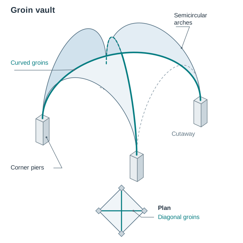
- Groin Vault: Formed by the perpendicular intersection of two identical barrel vaults over a crossing bay. Gravity loads and lateral thrusts concentrate along the diagonal intersection edges (groins), directing forces down to four corner piers and freeing up sidewalls for window openings.
- Rib Vault: First used in late Romanesque building and then developed fully in Gothic architecture, where skeletal arches concentrate the roof loads onto isolated piers. Slender exterior arches called flying buttresses channel the concentrated lateral thrust safely away from high clerestory walls into ground-level buttresses.
- Domes: A dome represents an arch rotated about its central vertical axis. The upper dome acts in compression along its meridional arches, while the lower part of the shell tends to spread outwards, which puts the base in circumferential (hoop) tension. Traditional masonry domes, such as the Pantheon in Rome, control this outward spreading through thick stepped rings at the base; Renaissance domes incorporated embedded iron chains or tension rings to restrain hoop stresses.
Modern Frames and Surface Structures
The introduction of structural steel and reinforced concrete enabled modern frameworks and thin-shell surface structures. While a triangulated steel frame (such as a stadium roof truss) resists distortion because a triangle cannot change shape without altering member lengths, thin-shell surfaces (such as concrete hyperbolic paraboloid canopies, hyperboloid cooling towers, or geodesic domes) derive their stiffness directly from 3D spatial curvature rather than material bulk.
Structural Properties and Graphical Setting-Out of Traditional Forms
At Higher Level, you must explicitly relate internal load paths to practical construction consequences.
| Structural Form | Primary Load Mechanism | Construction and Design Consequence |
|---|---|---|
| Arch | Compressive thrust acting along the line of the arch ring; outward lateral thrust at the springings. | Requires massive abutments, buttresses, or tie-rods; must be supported on temporary centring until the keystone is locked. |
| Barrel Vault | Continuous compressive arching; continuous lateral thrust along both sidewalls. | Sidewalls must be thick and solid; window penetrations must be small to prevent structural spreading. |
| Groin / Rib Vault | Loads channel along diagonal groins or structural ribs to isolated support piers. | Allows large stained-glass window openings in non-load-bearing curtain walls; flying buttresses absorb outward thrust at isolated piers. |
| Dome | Compressive meridional arches near the crown; circumferential tensile hoop stresses near the base. | Base requires a continuous tension ring beam or encircling chains; shell thickness can decrease toward the crown. |
| Triangulated Frame | Axial tension or compression along straight members with pinned joints. | Inherently rigid geometry; high strength-to-weight ratio without internal bending moments. |
| Hyperbolic Paraboloid | Anticlastic double curvature: tensile forces along sagging parabolas, compressive forces along arching parabolas. | Can be cast or assembled using straight timber boards or steel chords because the curved surface is doubly ruled. |
| Hyperboloid of Revolution | Doubly ruled surface resisting wind shear and axial compression through straight diagonal grids. | Fabricated from straight structural columns without steam-bending or curved casting; ideal for cooling towers and tall lattice masts. |
| Geodesic Dome | Loads are shared in every direction through a triangulated network of flat triangles, so no single member carries a large bending load. | Approaches the efficiency of a sphere: it encloses a large volume for a small surface area and a small weight of material, giving large column-free interiors. |
Setting Out Arches
In technical drawings, an arch is drawn as the centre line of the arch ring. The clear opening is the span, the level where the curve begins is the springing line, and the height of the crown above the springing line is the rise. The inner curve is the intrados and the outer curve is the extrados.
- Semicircular arch: Centre sits at the midpoint of the springing line; radius equals half the span; rise equals half the span.
- Segmental arch: The rise is less than half the span, so the centre lies below the springing line. Locate the centre by drawing the perpendicular bisector of the chord joining a springing point to the crown and extending it to intersect the vertical centre line.
- Equilateral (pointed) arch: Two centres, one located at each springing point. Both arcs have a radius equal to the full span and strike upward to meet at the pointed crown.
- Voussoir joints: Every joint line radiates directly from the centre of the arc. Divide the intrados into an odd number of equal parts so that a keystone sits symmetrically on the vertical centre line.
Dome and Vault Views
- Hemispherical dome: The plan is a circle of radius R, and the elevation is a semicircle of radius R. Meridians appear as radial lines in plan and as semicircles or semi-ellipses in elevation. Parallels (lines of latitude) appear as concentric circles in plan and as horizontal straight lines in elevation. Any horizontal cutting plane yields a circular section whose radius is projected directly from the elevation.
- Barrel vault: Elevation shows the true arch profile; plan is a rectangle whose width is the span and length is the axial extrusion.
- Groin vault: The plan of a square bay shows two straight diagonal lines crossing at the centre, representing the groins. The elevation across either axis shows the true semicircular arch profile.
3D Drawings by Ordinate Offsets
In isometric or axonometric views, circular arcs and arches distort into ellipses and cannot be drawn with compasses. Construct a 3D datum box aligned with the isometric axes. Divide the span in the orthographic elevation into equal vertical ordinates, measure the height of the curve at each ordinate, step these exact coordinates along the isometric axes, and trace a smooth, fair curve through the plotted points.
Line Diagrams and Environmental Investigations
A line diagram is a simplified single-line drawing showing the essential members, joints, and supports of a structure. In a line diagram, an arch is drawn as the centre line of its ring, and a framework or truss is drawn as the centre lines of its members, with arrows or labels showing where forces act (compression, tension, or thrust). To investigate and represent a structural form from the environment, follow a four-step routine: first, record a freehand sketch or photograph of the structure; second, construct a line diagram identifying its primary load paths and supports; third, produce orthographic plan and elevation views plus one 3D pictorial view; and finally, write one or two sentences naming the underlying geometry (such as a semicircular arch, hypar canopy, or hyperboloid cooling tower) and explaining how its form carries its loads.
Ruled Surfaces, Plane Directors, and the Ruled Hypar
A ruled surface is generated by the continuous movement of a straight line, known as a generator or element. If only one straight generator passes through each point, the surface is singly ruled—a cylinder and a cone are the familiar examples, and because their consecutive generators are parallel or meet at a point, these two can be developed (unrolled flat without distortion). If two different straight generators pass through every point, the surface is doubly ruled. Doubly ruled surfaces such as the hyperbolic paraboloid and the hyperboloid of revolution are warped: they are made of straight lines, but they cannot be developed flat, which is why they are built from straight members rather than bent sheet.
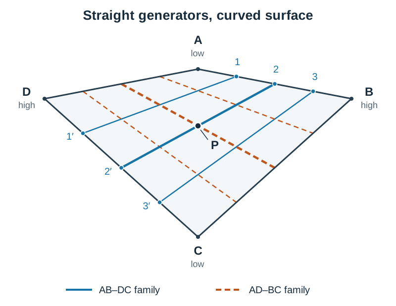
A hyperbolic paraboloid (hypar) is a doubly ruled, anticlastic (saddle-shaped) surface bounded by a skew quadrilateral ABCD whose four vertices do not lie in one plane.
How the Exam Question is Built
Section C questions on structural surfaces follow a consistent sequence:
- Convert all given dimensions using the stated scale before drawing.
- Draw the given view with the boundary quadrilateral ABCD.
- Divide opposite directrices and draw both families of straight elements.
- Project the second view of ABCD and its elements.
- Extend the elements to intersect a curved perimeter or boundary, establishing the curved outline.
- Locate any specified point P on the surface using an element.
- Insert the trace of the cutting plane, project element intersections, and draw the curvature of the cut.
- Construct the true shape of the section or curve using an auxiliary view on a new baseline.
Constructing the Ruled Surface
- Draw skew quadrilateral ABCD in plan and elevation.
- Divide AB and DC into the same number of equal parts using the standard construction: draw a line at any convenient angle from one end, step off the required number of equal units along it, join the last unit to the far end of AB, and draw parallels back to AB. Count divisions starting at A on AB and at D on DC, so that generator 1–1′ is nearest AD, and the boundary generators of this family are AD and BC.
- Join corresponding division points (1–1′, 2–2′, 3–3′) with straight lines in plan, and project them to the corresponding points in elevation.
- Divide AD and BC into the same number of equal parts and join matching points to draw the second family of generators.
Extending the Surface Beyond ABCD
Often ABCD defines the governing geometry, but the actual canopy, seat, or net extends to a curved perimeter (e.g. an ellipse or circle in plan). Because every element is a straight line, simply extend each straight element until it strikes the given boundary:
- In plan, extend each element of a family as a straight line at both ends to intersect the curved perimeter at points E and F.
- In elevation, extend that same straight element line beyond ABCD.
- Project E and F vertically up from plan onto that extended element line in elevation. This establishes the exact elevation heights.
- Repeat for all elements and join the plotted points with a smooth curve to complete the upper and lower edge curves.
Locating a Point on the Surface (Point P)
A point on a hypar must lie on an element of the surface. If P is given in plan and required in elevation:
- In plan, identify or draw the element passing through P. If P does not lie on an existing generator, draw a line through P parallel to neighbouring elements, cutting directrices AB and DC.
- Project the two ends of this line up to AB and DC in elevation, and join them with a straight line.
- Project P vertically from plan onto this line in elevation. The intersection fixes point P.
Plane Directors
A plane director is a reference plane to which all generators of a single family remain parallel. A hypar has two plane directors, one for each family.
- To find the plane director for generators spanning AB and DC, take the two boundary generators AD and BC.
- From corner A, draw a line parallel to BC in both plan and elevation. This line and AD intersect at A, defining the plane director.
- To find its edge view, draw a horizontal line on this plane in elevation, project it to plan (where it is in true length), and project an auxiliary view looking parallel to this true-length line.
Constructing a Ruled Surface Given Plane Director and Directrices
Every generator must touch both directrices and remain parallel to the plane director.
- If the plane director is horizontal, every generator is a level line. Draw horizontal lines at chosen heights across the directrices in elevation, find their intersections, join them, and project down to plan.
- If the plane director is oblique, project an auxiliary view that shows the plane director on edge. Project both directrices into this view. Any straight line drawn parallel to the edge view and intersecting both directrices represents a generator. Project the end intersections back to plan and elevation.
Sections, Curvature, and True Shapes of Ruled Surfaces
Understanding how cutting planes intersect a hyperbolic paraboloid is essential for scoring full marks in Section C.
Sections: Which View Shows the Curve
Vertical sections taken parallel to either axis of the surface are parabolas; horizontal sections are hyperbolas. That is where the name hyperbolic paraboloid comes from.
- Horizontal Cutting Plane: To find the curvature of a section cut by a horizontal plane passing through two points (such as B and D):
- In elevation, join B and D. This horizontal line is the edge view (trace) of the cutting plane.
- Mark every point where this trace crosses an element in elevation: 1, 2, 3...
- Project each point vertically down into plan onto the matching numbered element.
- Join the intersection points with a smooth curve. This curve is the required hyperbolic curvature in plan.
- Vertical Cutting Plane: To find the curvature cut by a vertical plane passing through two points (such as B and D):
- In plan, join B and D. This line is the edge view (trace) of the cutting plane.
- Mark where the trace crosses each element in plan.
- Project these crossings vertically up into elevation onto the corresponding elements.
- Join the plotted points in elevation with a smooth curve, which forms a parabola.
True Shape of a Section
"Show the curvature" means draw the curve as projected in one of the standard orthographic views. "Determine the true shape" requires looking perpendicular to the cut surface, which demands an auxiliary view.
Procedure for the true shape of a vertical section along trace BD in plan:
- In plan, mark where trace BD crosses each element: P1, P2, P3...
- Project each point up to its element in elevation to determine its vertical height above the XY line.
- Set up a new ground line X₁Y₁ parallel to trace BD in plan, positioned clear of the drawings.
- Project points P1, P2, P3... from plan perpendicular to X₁Y₁ (at 90° to the trace).
- Along each projector, measure and step off the corresponding vertical height taken from the elevation.
- Connect the plotted points with a smooth, continuous curve. This reveals the true shape of the section.
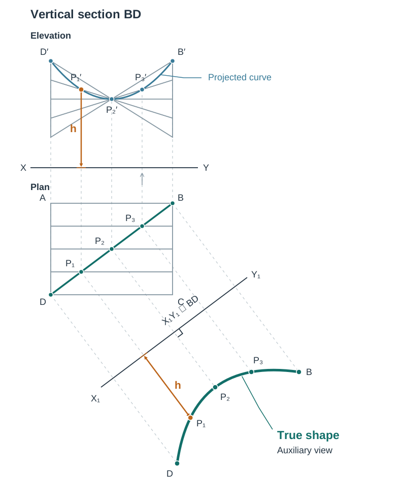
Golden rule: Widths along the new baseline come from the view showing the cutting plane on edge; heights are transferred from the view showing the plane as an area.
The Hyperbolic Paraboloid as a Surface of Translation
A hyperbolic paraboloid is also a surface of translation. A surface of translation is generated when a rigid profile curve (the generator curve) moves parallel to itself along another guiding curve (the director curve), without rotating.
For a hypar, both curves are parabolas in mutually perpendicular vertical planes, curving in opposite directions:
- The director parabola curves upwards (sagging, concave upwards), positioned parallel to the vertical plane and appearing in true shape in elevation (e.g. curve EBD with vertex B).
- The generator parabola curves downwards (arching, concave downwards), positioned parallel to the end vertical plane and appearing in true shape in the end view (e.g. curve ABC with vertex B).
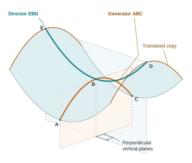
Graphical Projection Steps
Heights on the surface are found by graphical projection, not by algebraic calculation.
- In elevation, construct director parabola EBD using the rectangle method.
- In the end view, construct generator parabola ABC using the rectangle method.
- Divide the span of EBD in elevation into vertical station lines, and project these across the plan.
- In the end view, draw copies of generator parabola ABC with their vertices set to the heights of the director curve at each station.
- Project lateral widths from the end view into plan, and project heights from elevation across to establish the surface boundaries and contour curves.
Arithmetic Check: If you wish to verify a plotted height mathematically, the surface height z simply combines the two parabola offsets relative to central vertex height z₀: .
The Hyperboloid of Revolution and its Sections
A hyperboloid of revolution (of one sheet) is an open, hourglass-shaped, doubly ruled surface generated either by revolving a hyperbola about its conjugate (vertical) axis, or by revolving an inclined straight generator around a vertical axis to which it is skew.
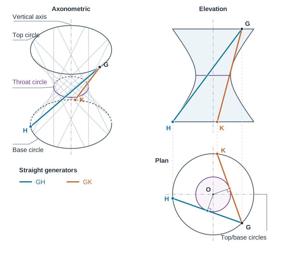
Principal Geometry
- Throat Circle: The horizontal circle of minimum diameter, located at the waist where generators pass closest to the axis. In plan view, every straight generator appears tangent to the throat circle.
- Base and Top Circles: Horizontal circular boundaries capping the ends of the form.
- Asymptotic Cone: A double cone whose apex sits at the centre of the throat circle on the vertical axis. The generators of this cone are parallel to the asymptotes of the hyperbolic elevation profile.
Drawing Projections and Asymptotes
- In plan, draw concentric top, base, and throat circles from centre O.
- Draw a line tangent to the throat circle in plan, extending from base circle point H to top circle point G. Line GH is one straight generator.
- Project G to the top level and H to the base level in elevation. Join G and H with a straight line. It crosses the throat line at the exact point where the plan tangent touches the throat circle.
- Draw the second family generator from G tangent to the opposite side of the throat circle, meeting the base at K.
- Asymptotes: In plan, a generator tangent to the throat circle and parallel to the vertical plane defines the asymptote slope in elevation: , where R is top/base radius and r is throat radius.
- Focus (F): From the throat circle vertex in elevation, draw a vertical line up to intersect the asymptote. Using the centre of the throat circle as centre, swing an arc from this intersection down onto the horizontal throat axis to fix focus F, satisfying .
- Directrix (D): Note that 'directrix' here means the directrix of the hyperbola — the fixed line that, together with the focus, defines the curve — not the boundary curve of a ruled surface. With compass centred at the throat centre, strike an arc of throat radius a to cut the asymptote. Drop a vertical line from this intersection across elevation to define the directrix, located at .
Sectioning the Hyperboloid
- A horizontal cutting plane gives a circle. Read its radius off the elevation outline at that height and draw it directly in plan.
- A cutting plane through the vertical axis reveals the true hyperbolic profile (both branches).
- An inclined cutting plane must be plotted using generators: draw several generators in plan and elevation, mark where the cutting plane crosses each generator in elevation, project those crossing points down to the same generators in plan, and connect them with a smooth curve. For the true shape, take an auxiliary view parallel to the cutting plane in elevation.
Spherical Geometry, Platonic Solids, and Geodesic Domes
A geodesic dome is a spherical space lattice composed of straight structural struts forming rigid planar triangles that approximate the curvature of a sphere.
Great Circles vs Lesser Circles
- Great Circle: A circle formed by passing a cutting plane directly through the centre of a sphere. Its centre and radius are identical to those of the sphere. The shortest path between any two points along a spherical surface lies on a great circle arc (a geodesic). Primary structural ribs follow great circles to transfer loads efficiently.
- Lesser Circle: Any circle on a sphere formed by a plane that does not pass through the centre of the sphere (e.g. horizontal lines of latitude). While useful as horizontal ring cut-offs, lesser circles do not provide the uniform load transfer of great circles.
The Five Platonic Solids
A regular polyhedron has identical regular polygon faces with the same number of faces meeting at every vertex. In three-dimensional space, only five convex regular polyhedra exist because the sum of the interior face angles meeting at any 3D vertex must be strictly less than 360°:
- Equilateral Triangles (60°):
- 3 faces: Tetrahedron (4 faces, 4 vertices, 6 edges).
- 4 faces: Octahedron (8 faces, 6 vertices, 12 edges).
- 5 faces: Icosahedron (20 faces, 12 vertices, 30 edges).
- 6 faces: (flat plane; cannot form a 3D corner).
- Squares (90°):
- 3 faces: Cube / Hexahedron (6 faces, 8 vertices, 12 edges).
- 4 faces: (flat plane).
- Regular Pentagons (108°):
- 3 faces: Dodecahedron (12 faces, 20 vertices, 30 edges).
- Regular Hexagons (120°):
- 3 faces: (flat plane; impossible to enclose volume).
Because the icosahedron has the most faces of the Platonic solids and all 12 vertices touch the circumscribing sphere, it is the usual starting point for subdividing a geodesic dome.
Geodesic Dome Frequency (Up to Frequency 4)
Frequency (n) defines the number of equal segments into which each primary edge of an icosahedron's triangular face is divided. Subdividing each edge into n parts produces n² smaller triangles per primary face:
| Frequency (n) | Edge Divisions | Small Triangles per Face | Typical Characteristics |
|---|---|---|---|
| 1V | 1 | Unsubdivided icosahedron; faceted and angular. | |
| 2V | 2 | Edges bisected; requires 2 distinct strut lengths (A and B). | |
| 3V | 3 | Edges trisected; requires 3 distinct strut lengths. | |
| 4V | 4 | Edges divided into 4 parts; highly spherical, multi-hub geometry. |
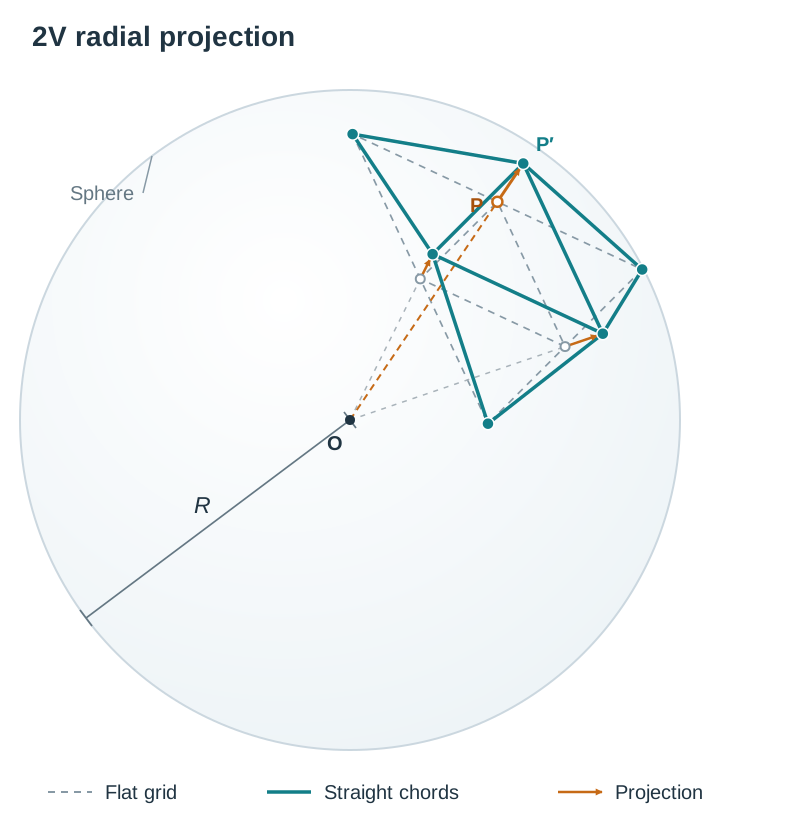
Radial Projection of Dome Nodes (Rotation Method)
Subdividing a flat icosahedral face creates grid points that sit inside the sphere. To position the dome hubs on the spherical surface, each point must be projected radially outward from sphere centre O to radius R:
- In plan, identify subdivision node P at distance r from vertical centre axis O.
- Rotate radius OP in plan around centre O until it lies horizontal (parallel to the XY line).
- Project this rotated point vertically into elevation to intersect the horizontal height line of point P.
- From centre O in elevation, draw a ray through that plotted point and extend it until it meets the circle of radius R (the circumscribing outline of the sphere).
- From that intersection, read off two values: the new horizontal distance from the axis, r′, and the new height, z′.
- In plan, swing r′ back along the original radial line OP (the direction of P is unchanged by radial projection) to fix the plan of the node.
- Project that plan position up into elevation and bring the height z′ across to meet it. Repeat for every subdivision point and join neighbouring nodes with straight chords.
Key terms
- Voussoir
- A wedge-shaped masonry stone used in constructing an arch ring, held in compression with the central block termed the keystone.
- Centring
- Temporary timber framework used to support voussoirs during the construction of an arch or vault until the keystone is locked into place.
- Springing
- The level line or support surface where an arch, vault, or dome curve begins its upward rise from a wall or pier.
- Thrust
- The outward horizontal force exerted at the springings or base of an arch, vault, or dome, requiring resistance from abutments, buttresses, or tie-rods.
- Buttress
- A massive exterior masonry support built against a wall to counteract the lateral outward thrust of an arch or vault.
- Groin
- The curved diagonal ridge line created by the perpendicular intersection of two identical barrel vaults.
- Ruled Surface
- A curved 3D surface generated by sweeping a continuous straight line (generator) along designated boundary directrices.
- Generator
- A straight line that moves along directrices to sweep out and form a ruled surface; also called an element.
- Directrix
- A fixed boundary line or curve along which the straight generators of a ruled surface travel during generation. (In conic sections the same word has a different meaning: the fixed line used with the focus to define the curve.)
- Singly Ruled
- A surface through which only one straight generator line passes through each surface point (e.g. cylinder, cone, conoid).
- Doubly Ruled
- A surface containing two independent families of straight generators passing through every single surface point (e.g. hyperbolic paraboloid, hyperboloid of revolution).
- Warped
- A ruled surface in which consecutive generators are neither parallel nor intersecting, preventing it from being developed flat.
- Developable
- A curved surface that can be unrolled or unfolded flat onto a single plane without stretching, tearing, or distortion (e.g. cylinder, cone).
- Hyperbolic Paraboloid
- A doubly ruled, anticlastic surface whose vertical sections parallel to the axes are parabolas and horizontal sections are hyperbolas.
- Anticlastic
- A saddle-shaped surface possessing opposite signs of curvature at every point: curving upwards in one direction and downwards in the transverse direction.
- Plane Director
- A geometric reference plane to which all straight-line generators belonging to a single family in a ruled surface remain strictly parallel.
- Surface of Translation
- A curved 3D surface produced by translating a rigid generator curve along a director curve while maintaining parallel orientation.
- Hyperboloid of Revolution
- A doubly ruled, hourglass-shaped surface generated by revolving a hyperbola or a skew straight line around a vertical axis.
- Throat Circle
- The horizontal circle of minimum diameter on a hyperboloid of revolution, to which every straight generator is tangent in plan view.
- Asymptote
- A straight line through the centre of a hyperbola that the hyperbolic profile curve approaches infinitely closely but never touches.
- Great Circle
- A circle inscribed on a sphere whose centre and radius coincide exactly with the centre and radius of the sphere itself.
- Lesser Circle
- Any circle formed on a sphere's surface by a cutting plane that does not pass through the centre of the sphere.
- Geodesic Dome
- A spherical space frame composed of straight structural struts forming rigid planar triangles based on great circle arcs.
- True Shape
- The undistorted view of an inclined or curved section obtained on an auxiliary plane viewed perpendicular to the cutting plane.
Check yourself
A vertical cutting plane cuts a hypar along the diagonal BD. In which view do you mark the trace, and in which view do you draw the resulting curve?
Mark the trace as a straight line in the view where the plane appears on edge (plan), then project each crossing point up onto its matching element in elevation and draw the curve there.
What is the difference between showing the curvature of a section and determining its true shape?
Curvature is the curve as projected in one of the given orthographic views; true shape requires an auxiliary view with the ground line parallel to the trace, with widths along the trace and heights taken from the other view.
Why does an arch require massive abutments or buttresses at its springings?
An arch converts vertical gravity loads into compressive forces along its curve, which generates an outward horizontal thrust at the springings that must be physically resisted to prevent spreading.
In plan view, what is the geometric relationship between any straight generator of a hyperboloid of revolution and its throat circle?
In plan view, every straight generator is tangent to the throat circle.
Why is it mathematically impossible to form a Platonic solid using regular hexagons?
Each interior angle of a regular hexagon is 120 degrees. Three hexagons meeting at a vertex sum to exactly 360 degrees, which forms a flat plane rather than a 3D vertex.
How many small triangles are created on each primary face of a 4-frequency (4V) geodesic dome?
Subdividing each edge into 4 segments creates 4 squared = 16 small triangles per primary face.