
Solids in contact deals with representing three-dimensional geometric bodies that touch tangentially without interpenetrating, and locating their exact points of contact (POC). In Leaving Certificate Design and Communication Graphics at Higher Level, questions require you to construct orthographic views of spheres, cones, cylinders, and plane-faced solids in mutual contact, establish precise contact points across all views, reconstruct solids backwards from a given point of contact, and set up auxiliary projection planes or rotation paths to solve spatial arrangements.
The Governing Geometric Principle: Tangent Planes and Surface Normals
Every contact problem in descriptive geometry rests on a single governing rule: at the point of contact (POC), both touching surfaces share a common tangent plane. The straight line perpendicular to this shared tangent plane at the POC is the surface normal. Because the normal is at right angles to the tangent plane, it provides the direct geometric link between the shapes:
- For a sphere, every surface normal passes directly through the centre of the sphere. The distance along the normal from the centre to the POC equals the sphere's radius r.
- For a cylinder, every surface normal passes through the central longitudinal axis and is perpendicular to it.
- For a cone, the surface normal passes through the central axis and is perpendicular to the specific straight-line generator (generatrix) passing through the POC. It never points towards the cone apex.
- For a planar face, the surface normal is perpendicular to the flat face or plane.
In standard orthographic views, this normal line is usually foreshortened because it slopes relative to both the horizontal plane (HP) and vertical plane (VP). Your central task is to identify or construct a view where the surface normal appears at its true length. Once the normal is shown in true length, the POC is found by drawing a simple perpendicular line, which can then be projected back to the primary views.
solids in contact versus interpenetration
Always check the command words on the exam paper. If the question asks you to 'show the point of contact' or mentions solids 'resting on' or 'in contact with' each other, the surfaces touch and stop. There is no curve of intersection. If the question asks for 'lines of interpenetration', the solids pass through each other and you must plot an intersection curve using cutting planes. Never draw an interpenetration curve on a contact question.
Setting Up Auxiliary Views: Projection Mechanics and True Length
Every contact solution involving inclined axes or sloping faces depends on setting up an auxiliary view correctly. A candidate who knows where to look can convert an awkward 3D problem into a simple 2D drawing.
Auxiliary elevation (projected from plan)
Draw the new ground line X1Y1 in the plan view. Project every point from the plan perpendicular to X1Y1. Measure the height of each point above the XY line in the original elevation, and transfer that exact height above X1Y1 into the auxiliary elevation. Heights never change between an elevation and an auxiliary elevation.
Auxiliary plan (projected from elevation)
Draw the new ground line X1Y1 in the elevation view. Project every point from the elevation perpendicular to X1Y1. Measure the distance of each point from the XY line in the original plan, and transfer that distance from X1Y1 into the auxiliary plan. Plan distances never change between a plan and an auxiliary plan.
Choosing the view direction
Align X1Y1 to put the critical line or plane into its most useful orientation:
- To see an inclined plane face as an edge view, look along a horizontal line on that plane: set X1Y1 perpendicular to that line in plan.
- To see the curved surface of a cylinder as a true circle, look along its axis: when the cylinder axis is parallel to the HP (horizontal), set X1Y1 perpendicular to the plan of the axis. (If the axis is inclined to both principal planes, first project an auxiliary view in which the axis appears in true length, then project a second auxiliary view perpendicular to it—looking along the axis—in which the cylinder appears as a true circle).
- To see a line of centres in true length, set X1Y1 parallel to the plan of that line.
A sphere projects as a circle of its true radius in every orthographic view, including auxiliary views. You never need an auxiliary view to draw a sphere, only to locate its centre.
Spheres in Contact: Reference Planes, Plan Distance, and the Ratio Rule
When a sphere of radius r touches the horizontal plane, its centre sits at a vertical height of exactly r above the ground line (XY). When it touches the vertical plane, its plan centre lies at a perpendicular distance of r from XY.
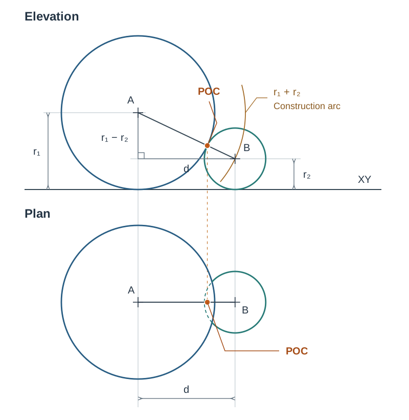
When two spheres of radii r1 and r2 touch externally, their centres in space are separated by a true distance of r1 + r2. The line of centres connects the two sphere centres, and the POC lies directly on this line at a distance r1 from the first centre.
Unequal spheres on the HP
Because their centres sit at different heights (r1 and r2), the line of centres slopes in space. In plan, this line is foreshortened, meaning the plan distance between centres is shorter than r1 + r2. As a result, their circular outlines overlap in plan even though the spheres touch externally without penetrating.
Always construct the plan distance graphically: draw a horizontal centre-height line at height r2 in elevation. From the centre of the first sphere at height r1, strike an arc of radius r1 + r2 down to cut this height line. The horizontal distance between the two centres is the true plan distance. Transfer this span directly to plan with your compass or dividers.
You can verify the plan distance mathematically using Pythagoras: d(plan) = √((r1 + r2)² − (r1 − r2)²) = 2√(r1 × r2). On an exam sheet, however, marks are awarded for the visible construction arc, not an unconstructed numerical measurement.
The ratio rule for the point of contact
Because orthographic projection preserves the ratio of lengths along any straight line, the POC divides the projected line of centres in both plan and elevation in the exact ratio of the radii, r1 : r2. For spheres of radii 30 mm and 20 mm, the POC lies precisely 3/5 of the way from centre A to centre B in plan, and 3/5 of the way from centre A to centre B in elevation. This allows you to mark the POC directly on the line of centres in both views without needing a separate true-length view.
Sphere in Contact with an Inclined Plane Face
A sphere touching a flat surface is one of the most common setups in Section A. The surface normal is perpendicular to the plane face. Therefore, in any view where the face appears as an edge view (a single straight line), the normal appears in true length as a simple perpendicular line.
Simply inclined face (edge view in elevation)
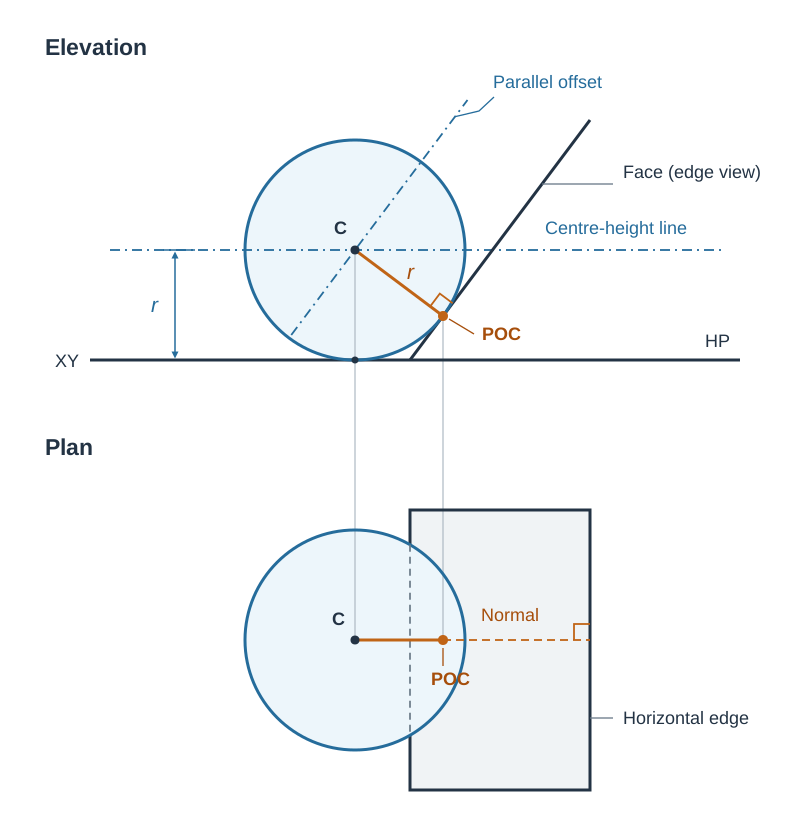
When a face slopes up from the HP but is perpendicular to the VP, it appears as an edge view in elevation. To position a sphere of radius r touching this face and resting on the HP:
- In elevation, draw the edge view of the sloping face.
- Draw a line parallel to the edge view, offset from it by a perpendicular distance equal to the sphere radius r on the side where the sphere rests. Every sphere of radius r touching that face has its centre on this line.
- Draw the centre-height line horizontally at height r above XY.
- Where the parallel offset line cuts the centre-height line is the sphere centre C in elevation.
- From C, drop a perpendicular onto the edge view of the face. The foot of that perpendicular is the point of contact in elevation.
- In plan, the normal line lies along the line of greatest slope of the face (perpendicular to the horizontal edges of the face in plan). Draw that direction through the plan position, then project C and the POC down from elevation to fix their positions in plan.
- Draw the sphere as a circle of radius r in both views and label POC in both.
If the face is obliquely inclined, it does not appear as an edge view in either primary view. Project an auxiliary view that shows the face as an edge view, apply the steps above, and project the centre and POC back to the primary views.
Sphere and Cylinder Contact: Auxiliary Views Along the Axis
When an upright vertical cylinder touches a sphere on the HP, the line connecting their centres is horizontal. The POC in elevation sits at the exact vertical height of the sphere centre, and in plan both solids project as circles touching on the line of centres.
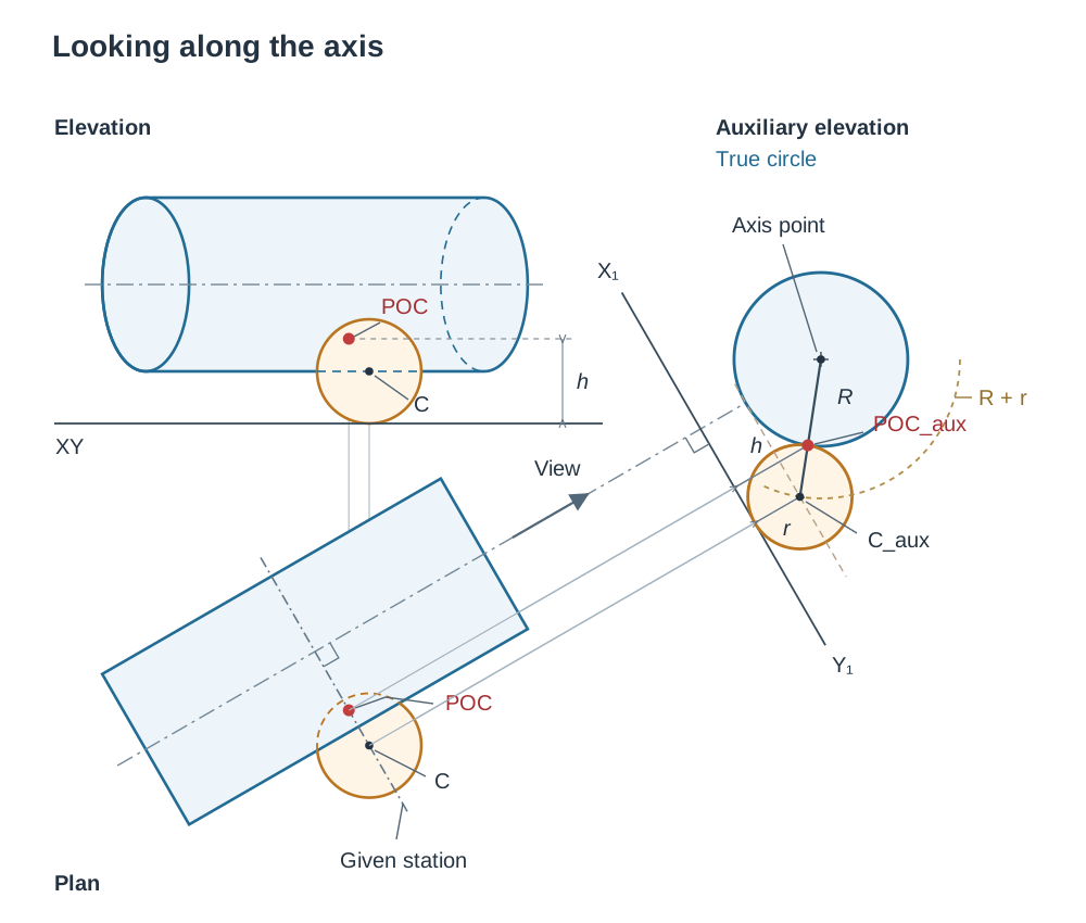
When the cylinder axis is horizontal but inclined to the VP in plan, its circular end faces project as ellipses in elevation and its curved surface projects as two straight outlines parallel to the axis, so neither primary view shows the cylinder as a true circle. A single auxiliary elevation works when the cylinder axis is parallel to the HP (horizontal), because looking perpendicular to X1Y1 in plan is looking directly along the axis. (If the axis is inclined to both principal planes, first project an auxiliary view in which the axis appears in true length, then project a second auxiliary view perpendicular to it—looking along the axis—in which the cylinder appears as a true circle). For a cylinder with its axis parallel to the HP, proceed as follows:
- In plan, draw a new ground line X1Y1 perpendicular to the plan of the cylinder axis.
- Project the cylinder along its axis into the auxiliary view. Transfer heights from the original elevation. Because the axis is horizontal, it projects as a single point and the cylinder projects as a true circle of radius R.
- Draw a horizontal line at height r above X1Y1 to represent the height of the sphere centre resting on the HP.
- From the point where the cylinder axis appears as a point in the auxiliary view, strike an arc of radius R + r to cut the sphere centre-height line. This works because the line from the sphere centre perpendicular to the cylinder axis appears in true length in this view. This intersection fixes the sphere centre in the auxiliary view, C_aux.
- Join the cylinder axis point to C_aux with a straight line. Where this line crosses the cylinder circle is the auxiliary contact point, POC_aux.
- Project C_aux and POC_aux back perpendicular to X1Y1 into plan along projector lines parallel to the axis. Use the given station or distance along the axis to locate them precisely, then project vertically into elevation, taking heights directly from the auxiliary view.
Sphere in Contact with an Upright Cone: The Rotation Method
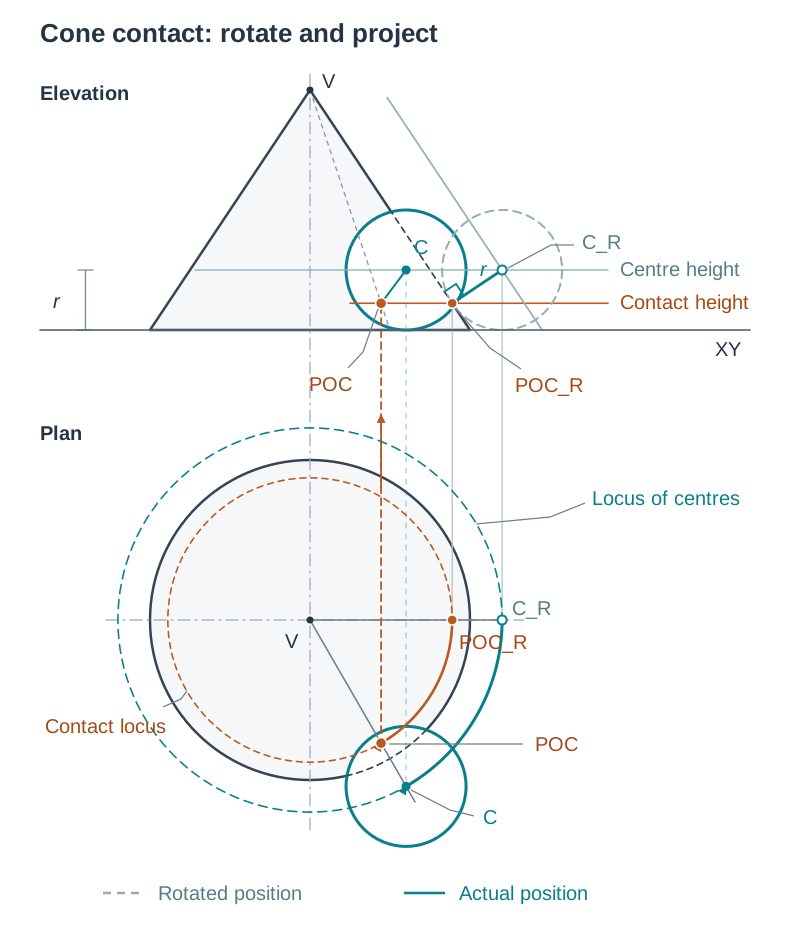
When a sphere touches the curved lateral surface of an upright right cone, the contact occurs along a straight-line generator. In plan, the cone apex, the sphere centre, and the POC are always collinear. If the sphere touches the cone anywhere other than the extreme left or right outline in elevation, the contact generator is inclined to the VP and foreshortened, meaning you cannot construct a 90° normal directly in elevation.
To solve this, use the rotation method:
- In elevation, draw an offset line parallel to the cone's extreme generator at a perpendicular distance equal to the sphere radius r.
- Draw a horizontal line at the sphere centre height (height r above XY if resting on the HP). The intersection of this offset line with the centre-height line locates the sphere centre in its rotated elevation, C_R.
- From C_R, drop a line perpendicular to the extreme generator. The point where this perpendicular meets the generator is the rotated point of contact, POC_R. Carry a faint horizontal height line across from POC_R.
- In plan, measure the horizontal distance from the cone axis to C_R in elevation. Using this distance as a radius, swing a circle centred on the cone apex V. This circle is the locus of centres.
- Position the plan centre C on this circular locus according to the problem constraints (such as a given angle, an offset, or contact with another solid). In plan, join V to C with a straight line.
- In elevation, measure the horizontal distance from the cone axis to POC_R. In plan, draw a circle about V with that distance as radius. This is the horizontal circle on the cone surface containing the contact point. Where this circle cuts the plan line VC is the true plan of the POC.
- Project the plan POC vertically into elevation to meet the horizontal height line carried across from POC_R. Label POC in both views.
Reversing the Construction: Locating Solids from a Given Point of Contact
You will also be asked to work the construction backwards: 'Construct the views of a sphere of radius r which touches the surface at the given point of contact P.' This directly addresses the syllabus outcome 'construct views of solids given the point of contact'.
To reconstruct any solid backwards from a POC, establish the surface normal at P, find a view where that normal appears in true length, and measure the sphere radius r along that normal away from the surface.
| Surface Touched at Point P | Orientation of the Surface Normal | Construction to Locate Unknown Sphere Centre |
|---|---|---|
| Existing sphere (centre C1) | Passes through C1 and P. | Connect C1 to P and extend outward by radius r in a view showing C1P in true length. |
| Flat inclined face | Perpendicular to the flat face. | Project an auxiliary view showing the face as an edge view. At P, erect a perpendicular and step off radius r. |
| Cylinder curved surface | Perpendicular to the cylinder axis. | View along the axis so the cylinder appears as a true circle. Draw a radial line from the axis through P and step off radius r outward. |
| Cone curved surface | Perpendicular to the generator through P. | Rotate the generator containing P parallel to the VP in elevation. Erect a perpendicular to that generator at P and step off radius r. |
Plane-Faced Solids, Mutual Contact of Three Solids, and 3D Visualisation
Contact is not limited to curved surfaces. The syllabus requires solving right solids with plane and curved surfaces in mutual contact.
Right solids with flat faces
Contact between plane-faced solids occurs in three forms: face on face (contact is a shared area), edge on face (contact is a straight line), or vertex on face (contact is a single point). To solve these, project an auxiliary view where the supporting face appears as an edge view. The resting solid sits directly on this line. If its base needs to be positioned accurately, project a second auxiliary view perpendicular to the edge view to show the supporting face in true shape, draw the resting solid's base at true size, and project back.
Mutual contact of three solids
When an unknown sphere touches two fixed solids while resting on the HP, its centre lies at the intersection of two loci in plan. Resting on the HP fixes its centre height at r. Touching a fixed sphere A gives a circular plan locus centred at A with radius d_A = √((r_A + r)² − (h_A − r)²), where h_A is the height of sphere A's centre. Touching a second solid gives a second plan locus (another circle from a sphere, or a concentric circle from a cone). The intersection of these two plan loci fixes the plan centre of the third sphere. Two intersections are usually possible; inspect the given drawing or pictorial view to choose the correct side.
Visibility and 3D sketching
Before drafting your orthographic solution, make a quick freehand 3D sketch of the solids, the ground plane, and the normal. This makes it immediately clear which view will show the normal in true length. In CAD modeling software, solids in contact are positioned using tangent or mate constraints rather than guessed coordinates.
To decide hidden detail:
- In plan, at any place where two outlines overlap, the surface that is higher in the elevation is drawn as a continuous outline and what lies beneath it is dashed.
- In elevation, at any place where two outlines overlap, the surface that is further from XY in plan (nearer the front) is continuous and what lies behind it is dashed.
Key terms
- Point of Contact (POC)
- The exact geometric point where two surfaces touch tangentially without intersecting. It must be clearly identified and labelled across plan, elevation, and auxiliary views.
- Surface Normal
- A straight line perpendicular to the common tangent plane at the point of contact. For a sphere, it passes through the centre; for a cylinder, it is perpendicular to the axis; for a cone, it is perpendicular to the contact generator.
- Line of Centres
- The straight line joining the centres of two touching spheres, along which the point of contact lies. For a sphere touching a cylinder, the corresponding line is the perpendicular from the sphere centre to the cylinder axis; for a cone, it is the perpendicular to the contact generator.
- Common Tangent Plane
- The single flat plane that touches both solids tangentially at their point of contact, separating their interiors without penetrating either solid.
- Generator (Generatrix)
- A straight line lying entirely on the curved surface of a cone or cylinder that connects the base to the apex or runs parallel to the axis.
- Extreme Generator
- The outermost visible outline of a cone or cylinder in an orthographic view, representing a generator oriented parallel to the projection plane and displaying true slope.
- Edge View
- An orthographic projection in which a flat plane or face appears as a single straight line, allowing true perpendicular offsets and normal lines to be drawn directly.
- Locus of Centres
- The line, circle, or surface containing every possible spatial position of a solid's centre while satisfying a specific contact constraint.
- Auxiliary Elevation
- A projection onto a plane perpendicular to the horizontal plane, projected from the plan with an X1Y1 line, where heights above XY are transferred directly from the front elevation.
- Hidden Detail
- Evenly spaced dashed lines representing edges and surface contours obscured by other solid geometry closer to the viewer.
Check yourself
Two spheres of radii 36 mm and 16 mm rest on the HP in mutual contact. What is their true spatial distance between centres, and what is their plan distance between centres?
The true spatial distance between centres is r1 + r2 = 36 + 16 = 52 mm. The plan distance is 2√(r1 × r2) = 2√(36 × 16) = 2√(576) = 2 × 24 = 48 mm.
A sphere of radius 18 mm rests on the HP and touches a face that appears in elevation as an edge view inclined at 50° to XY. How do you find the sphere centre and the point of contact in elevation?
Draw a line parallel to the 50° edge view, offset 18 mm perpendicular to it into the open space. The intersection of this offset line with a horizontal line 18 mm above XY is the centre C. Drop a perpendicular from C onto the edge view; the foot of this perpendicular is the point of contact.
Where does the point of contact lie in plan when a sphere touches an upright right cone?
It lies directly on the straight line connecting the plan apex V of the cone to the plan centre C of the sphere.
When projecting an auxiliary elevation from a plan view, what measurement is transferred from the existing drawing?
Vertical heights above the XY line in the elevation are transferred directly as heights above the X1Y1 line in the auxiliary elevation. Heights never change.
In plan, two solids overlap in outline. How do you determine which lines should be drawn as continuous firm lines and which as dashed hidden lines?
Inspect the elevation at the overlapping position and determine which surface is higher there. The surface that is higher in elevation at that position is drawn with a continuous firm outline, while the surface lying beneath it is drawn with dashed hidden lines.