
Skew lines are straight lines in three-dimensional space that are neither parallel nor intersecting. Because they do not lie in a common plane, they are non-coplanar. You cannot read the true clearance between them, or the true angle between them, straight off the given plan and elevation — both views foreshorten the lines, so every measurement has to be taken in a specially constructed auxiliary view. Nearly all skew-line problems are solved by putting the two lines into an auxiliary view where their true relationship can be seen. There are two standard routes: the containing plane method (building a plane through one line, parallel to the other), which is required whenever the connector must be horizontal or at a stated slope; and the point view method (finding the true length of one line, then looking along it), which is quicker when the question simply asks for the shortest distance.
Recognising Skew Lines and Orthographic Conventions
In two dimensions, any two straight lines either meet at an intersection point or run parallel. In three-dimensional space, a third condition exists: skew lines.
Two spatial lines are skew when they satisfy three conditions:
- They are not parallel to each other.
- They do not intersect at any point in space, even when extended indefinitely.
- They do not lie in a common plane (they are non-coplanar).
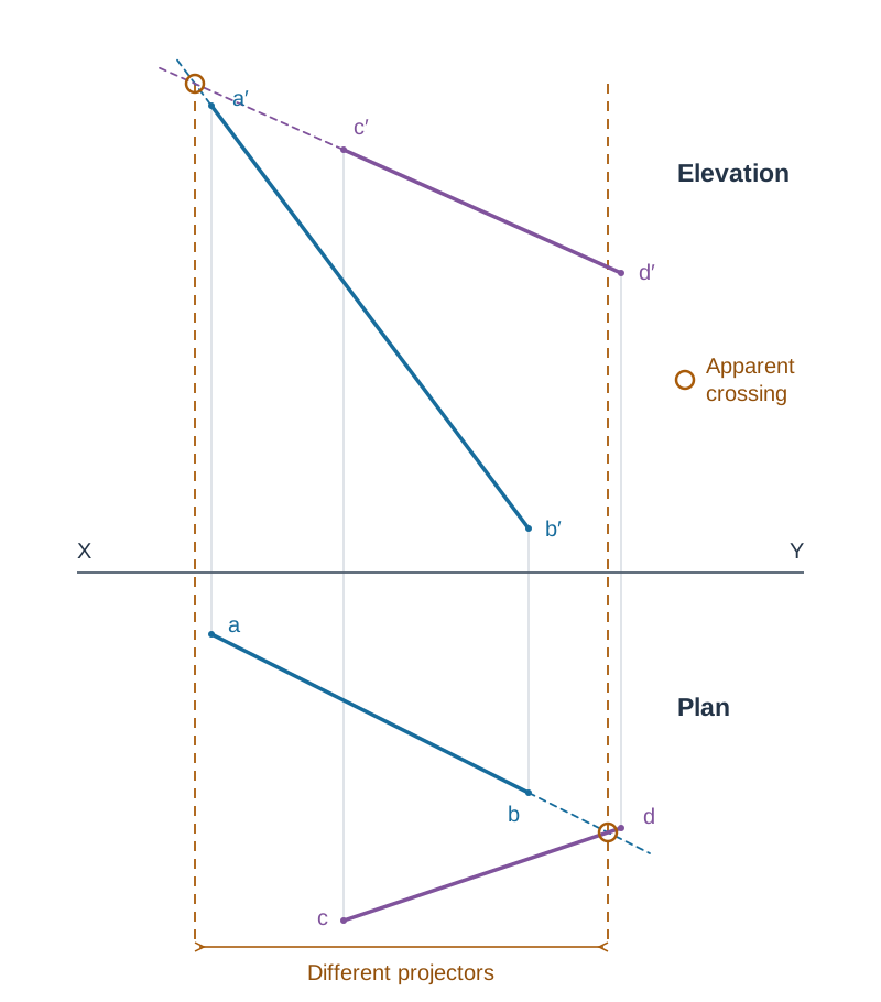
In orthographic drawings, two lines often appear to cross over each other in plan or elevation. An apparent crossing is not proof of an intersection. It only means that one line passes in front of, behind, above or below the other along that direction of sight. The crossing is a real intersection only when the crossing point in the plan and the crossing point in the elevation lie on the same vertical projector.
| Relationship in Space | What You See in Plan and Elevation |
|---|---|
| Parallel lines | Lines are parallel in plan and parallel in elevation. |
| Intersecting lines | The crossing point in elevation and the crossing point in plan lie on the same vertical projector. |
| Skew lines | The lines are not parallel in both views at once (they may look parallel in one view only), and any apparent crossing points in plan and elevation do not lie on the same vertical projector. |
Parallel in space means parallel in plan and in elevation. Parallel in only one view means the lines are not parallel at all.
Standard Labelling Conventions
Keeping your labelling consistent prevents confusion when transferring dimensions across multiple projection planes:
- Plan points are labelled with lower-case letters: .
- Elevation points carry a prime: .
- First auxiliary points carry a subscript 1: .
- Second auxiliary points carry a subscript 2: .
The Containing Plane Principle and Method Selection
To control the direction of a connecting line between two skew lines, you establish a containing plane.
Given two skew lines, and :
- Pick an endpoint on one line, such as point on line .
- Through , draw a construction line parallel to line in the plan and in the elevation (, and ). Point can be placed at any convenient distance along this line so that it stays neatly on the drawing sheet. A line is only parallel to another in space when it is parallel in both views.
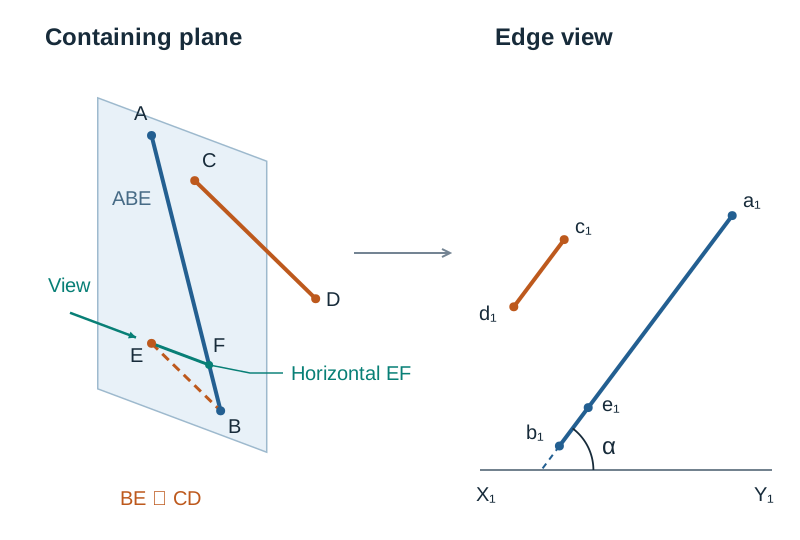
- Because and meet at , they form plane .
Because line is parallel to line on this plane, is parallel to the entire plane , maintaining a constant clearance from it.
Projecting the Edge View of Plane ABE
To view plane as a single line (an edge view), you must look directly along a true length line lying on that plane. The standard choice is a horizontal line (strike line):
- In elevation, draw a horizontal line across plane parallel to the line. For example, draw a level line through to cut line at .
- Project vertically down to line in plan to locate . Join to . Because line is horizontal in space, its plan view shows its true length.
- Draw the first auxiliary ground line perpendicular to in plan. Choose a position for that directs the projected views into clear space on your sheet.
- Project all points (, and check point ) perpendicular to . Transfer vertical heights directly from the elevation, measuring from the line.
In this first auxiliary view:
- Points and align into a single line, forming the edge view of plane .
- Line projects parallel to line .
- The angle between and is the true inclination () of the plane to the Horizontal Plane (HP).
Choosing Your Second Auxiliary Ground Line ()
The orientation of determines what the second auxiliary view reveals:
| Problem Requirement | Required Method | Orientation of |
|---|---|---|
| Shortest perpendicular distance | Containing plane method | Draw parallel to the edge view (). |
| Shortest horizontal distance | Containing plane method | Draw perpendicular to . |
| Connector inclined at to HP | Containing plane method | Draw the connector at to in the first auxiliary; draw perpendicular to that connector. |
The Point View Method for Shortest Perpendicular Distance
If a question asks only for the shortest perpendicular distance (with no requirement for a horizontal or sloping connector), the point view method is faster because it does not require constructing a containing plane.
- First auxiliary (true length of AB): Draw parallel to line in plan. Project points and perpendicular to . Transfer heights from the elevation, measured vertically from . Line now appears at its true length.
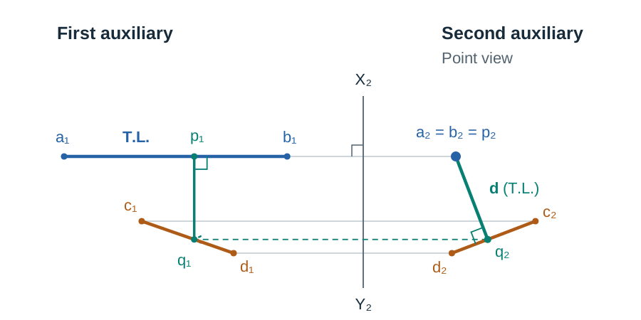
- Second auxiliary (point view of AB): Draw perpendicular to . Project all four points perpendicular to . Transfer distances from as measured in the plan view (the view two steps back). Line collapses into a single point: .
- Measure the distance: From the point , drop a perpendicular line onto line . Because you are looking directly along , this line is the common perpendicular and appears at true length. Measure it directly in millimetres.
- Project back to primary views: Project the contact point on back to the first auxiliary view (perpendicular to ) to locate it on . From that point, draw a line perpendicular to to locate the contact point on . Project both endpoints back perpendicular to into plan to land on and , and then vertically up to elevation to land on and . Firm in the connector.
Constructing the Shortest Horizontal Distance
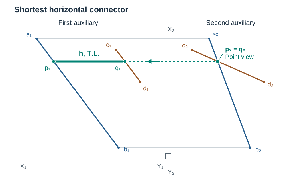
A level connector between skew lines must remain parallel to the Horizontal Plane. In the first auxiliary view projected from plan, the line represents the Horizontal Plane; therefore, every horizontal line in space appears parallel to .
- In the first auxiliary view, lines and run parallel. Draw a line parallel to between them. Its length is the true length of the shortest horizontal distance.
- To locate its exact position, set up perpendicular to . This directs your line of sight straight along the level direction.
- Project the lines across , transferring distances from back to the plan view.
- Lines and intersect. This crossing is the point view of the horizontal connector.
- Project this intersection point back to the first auxiliary view. It defines the horizontal segment running parallel to between and .
- Project both contact points back to plan (perpendicular to ) and then vertically up to elevation.
Self-Checks for Drafting Accuracy
Before firming in your solution, verify these two geometric checks:
- In elevation, the connector must be parallel to the line.
- In plan, the connector must be perpendicular to the strike line .
Trigonometric Check
In the first auxiliary view, the shortest perpendicular distance , the shortest horizontal distance , and the plane inclination angle form a right-angled triangle:
Because can never be greater than 1, the shortest horizontal distance is always at least as long as the shortest distance measured along the common perpendicular. They are equal only when the containing plane is vertical (). Use this formula strictly to check your measured drawing values, never as a replacement for graphical construction.
True Angle Between Lines (Skew vs Intersecting)
True Angle Between Skew Lines
Although skew lines never intersect, their directions form a spatial angle. In the second auxiliary view of the containing plane method (where is drawn parallel to the edge view ):
- Plane is viewed square-on, so both lines and appear at their true length.
- The angle between and is the true angle between the skew lines.
- Unless the question says otherwise, give the acute angle between the two lines.
True Angle Between Lines That Meet
If two lines share a common vertex (such as and meeting at ), they are coplanar. You do not construct an external containing plane; you find the true shape of the triangle they form.
Method 1 (Auxiliary view):
- Connect the endpoints to form triangle in plan and elevation.
- Draw a horizontal line across the triangle in elevation and project it down to plan to get its true length.
- Draw perpendicular to this true-length line in plan to project the triangle as an edge view.
- Draw parallel to the edge view to reveal the triangle in true shape. Measure the angle at with a protractor.
Method 2 (Rotation / True lengths):
- Find the true length of each of the three sides () by rotating each line in plan until it is parallel to , then measuring its length in elevation.
- Construct the triangle full size using compasses from these three true lengths.
- Measure the included angle at the shared vertex.
Key terms
- Skew Lines
- Straight lines in three-dimensional space that are non-parallel, non-intersecting, and non-coplanar.
- Containing Plane
- A construction plane drawn through one skew line parallel to the second skew line, causing both lines to appear parallel in an auxiliary edge view.
- Common Perpendicular
- The unique line segment in space that meets two skew lines simultaneously at right angles; its length is the absolute shortest distance between them.
- Shortest Perpendicular Distance
- The absolute minimum spatial distance between two skew lines, measured along their common perpendicular.
- Shortest Horizontal Distance
- The shortest connecting segment between two skew lines that lies completely parallel to the horizontal plane of reference.
- Strike Line
- A horizontal line constructed on an inclined plane; it runs parallel to XY in elevation and displays its true length in plan.
- Edge View
- A projection where a plane appears as a single straight line, produced by looking directly along a true length line lying on that plane.
- Point View
- A projection where a line appears as a single point, produced by looking directly along its true length.
- True Angle
- The angle between the spatial directions of two lines, measured in a view where both lines appear at their true length.
- Lines Produced
- The extension of line segments beyond their given endpoints to locate a point of intersection or common connector.
Check yourself
What three conditions prove that two lines in space are skew?
They are not parallel, they do not intersect at any point (even if extended), and they do not lie in a common plane.
In elevation, two lines cross at X = 45 mm; in plan, they cross at X = 70 mm. Are they intersecting or skew?
They are skew. A true intersection point must share the same vertical projector in both plan and elevation.
Why do lines AB and CD appear parallel in the first auxiliary view of the containing plane method?
Because line CD is parallel to plane ABE, any view that shows plane ABE as an edge view will also show CD running parallel to that edge.
How must the X2Y2 ground line be positioned to locate (a) the shortest perpendicular distance, and (b) the shortest horizontal distance using the plane method?
(a) Parallel to the parallel lines in the first auxiliary view. (b) Perpendicular to the X1Y1 ground line.
Two checks confirm that a shortest horizontal connector has been projected back correctly. What are they?
In elevation, the connector must be parallel to the XY line. In plan, the connector must be perpendicular to the plan of the strike line.
Try this construction: Line AB has coordinates A(20, 12, 100) and B(95, 48, 16); Line CD has coordinates C(50, 80, 92) and D(110, 60, 64). What are the steps to find the shortest horizontal distance?
Draw BE parallel to CD in plan and elevation. Draw a level strike line through E in elevation to cut AB at F, project F to plan, and set X1Y1 perpendicular to ef in plan. In the auxiliary view, measure the horizontal distance parallel to X1Y1 between the parallel lines. Set X2Y2 perpendicular to X1Y1 to locate the point view of the connector, then project back to plan and elevation.