
Perspective projection produces a pictorial drawing of a three-dimensional object showing how it appears to human vision from a fixed viewpoint. Unlike orthographic or axonometric systems where projection lines remain parallel, perspective uses visual rays that converge towards the observer's eye at a station point. Receding parallel lines converge towards vanishing points, and objects diminish in size as their distance from the viewer increases. In Leaving Certificate Design and Communication Graphics (DCG), perspective sits within the core under Projection Systems; perspective is a frequent Section B topic, where each question carries 60 marks and may be wholly or partly a perspective problem. While parallel (one-point) and angular (two-point) perspective for horizontal lines are common to both Ordinary and Higher Level, finding vanishing points for sets of inclined lines using auxiliary vanishing points (AVPs) is strictly Higher Level only. Mastering perspective geometry also underpins the high-quality 3D freehand sketching required in the Student Assignment.
Principles, Setup, and Sheet Layout
A perspective drawing coordinates a plan view and an elevation to generate a realistic pictorial projection. Understanding how the sheet is arranged prevents running vanishing points off the edge or misaligning projectors.
What your sheet should look like
- Upper zone: The picture plane is drawn as a horizontal line across the upper half of the sheet. The plan of the object sits behind this line (on the far side from the viewer). The spectator point sits in front of the picture plane (on the near side), positioned along the central line of vision.
- Lower zone: Directly beneath the plan, draw two horizontal baselines: the ground line at the bottom, and the horizon line positioned above it at a distance equal to the spectator's eye level. All perspective construction lines drop vertically from the picture plane line into this lower zone.
Converting scale data before drawing
Exam questions provide dimensions in metres along with a specified scale (such as 1:100 or 1:200). Always convert these dimensions to millimetres on your page before touching your instruments, and write them in the margin beside the question.
- At 1:100, 1 mm drawn represents 100 mm (0.1 m). A spectator distance of 16 m becomes . An eye level of 7 m becomes .
- At 1:200, 1 mm drawn represents 200 mm (0.2 m). A chimney 20 m high becomes .
The plan of the object is worth standalone marks in the marking scheme (often 8 marks or more). Draw it accurately and position it high and centrally on your sheet so that both vanishing points remain comfortably on the paper.
Angular (Two-Point) Perspective
In angular (two-point) perspective, the object is positioned so that its vertical faces are inclined to the picture plane. Vertical edges remain strictly vertical on the page, while receding horizontal edges converge towards two vanishing points on the horizon line.
Setting up the vanishing points
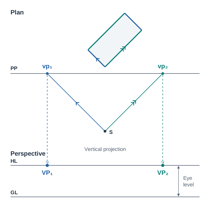
- In plan, draw a line from the spectator point parallel to the principal receding edges on one side of the object until it pierces the picture plane line at .
- From , draw a second line parallel to the receding edges on the other side of the object until it pierces the picture plane line at .
- Project and vertically downwards into the elevation until they cross the horizon line, establishing the vanishing point locations and .
It helps to keep the two apart when labelling: use and for the points where the parallel sightlines cut the picture plane in plan, and and for the points you project down onto the horizon line. Examiners look for both sets to be present and clearly labelled.
Projecting points to the perspective view
From spectator in plan, draw a visual ray to every corner and feature of the object. Where each visual ray cuts the picture plane line, drop a vertical projector straight down into the perspective view. The perspective position of that point lies along this vertical projector.
Parallel (One-Point) Perspective
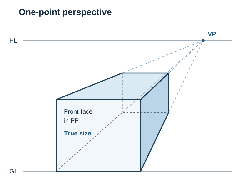
In parallel (one-point) perspective, one face of the object is parallel to the picture plane, and the depth edges run perpendicular to it.
Step-by-step setup
- In plan, draw a line from the spectator point perpendicular to the picture plane line. The point where this line pierces the picture plane is projected vertically down onto the horizon line. This single point is the centre of vision, which acts as the sole vanishing point ().
- Any face lying directly in the picture plane is drawn at its true shape and true size. Draw it directly from the elevation dimensions, taking heights straight up from the ground line.
- Connect every corner of this front face back to .
- To find depth, draw visual rays from to the rear corners of the object in plan. Where these rays cross the picture plane line, drop vertical projectors. Where each projector crosses the line receding to , mark the rear corner.
- Front and rear horizontal edges remain horizontal; vertical edges remain vertical. Only edges running parallel to the line of sight converge.
True Height Lines and Isolated Elements
Because perspective creates diminishing scale with distance, any feature behind the picture plane appears smaller than true size — the further behind it sits, the smaller it appears. Heights can only be marked at true scale on a true height line lying directly in the picture plane.
Corner touching the picture plane
When a front corner touches the picture plane in plan, drop that point vertically to the ground line. This line is a true height line. Measure true vertical heights directly up from the ground line along this vertical line, and vanish the height marks towards and .
Wall face sitting behind the picture plane
When an entire wall plane sits behind the picture plane, extend the line of that wall in plan forward until it intersects the picture plane line at a contact point . Drop vertically down to the ground line to create a true height line for that entire wall plane. Measure the true height up from the ground line at , and vanish it back towards the vanishing point for that wall. Where this receding vanishing line meets the vertical corner projectors dropped from the plan visual rays, it defines the correct perspective height.
Adding an isolated vertical element (pole, mast, chimney)
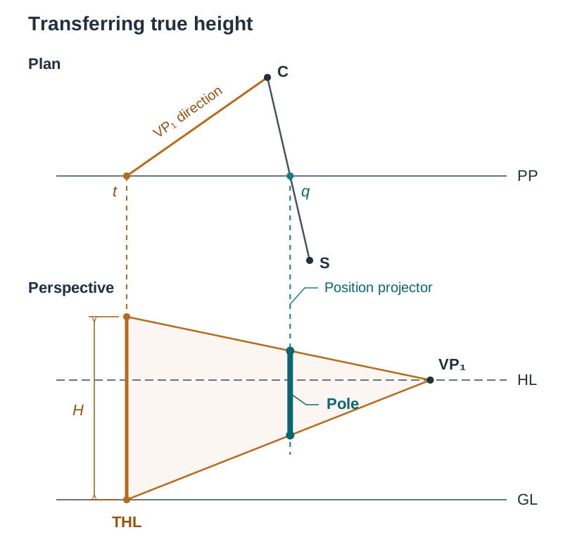
A vertical pole or chimney standing at a point behind the picture plane does not touch the picture plane, so it has no true height line of its own. You borrow one:
- In plan, draw the visual ray from to . Where it cuts the picture plane line, drop a vertical projector. The entire vertical element lies on this single line.
- Through point in plan, draw a line parallel to one of the object's principal directions — for example, the direction vanishing to — and extend it forward until it cuts the picture plane line at .
- Drop vertically to the ground line. This vertical line is your temporary true height line. Measure the full height of the element up from the ground line along this line.
- Connect both the base mark on the ground line and the top height mark at back to . Where these two vanishing lines cross the vertical projector from step 1, you find the perspective base and top of the pole.
Auxiliary Vanishing Points (Higher Level Only)
Sets of parallel lines that slope relative to the horizontal plane (such as mono-pitch or gabled roofs, canopies, ramps, and solar panels) do not converge on the horizon line. They vanish to an auxiliary vanishing point (AVP).
Why the construction works
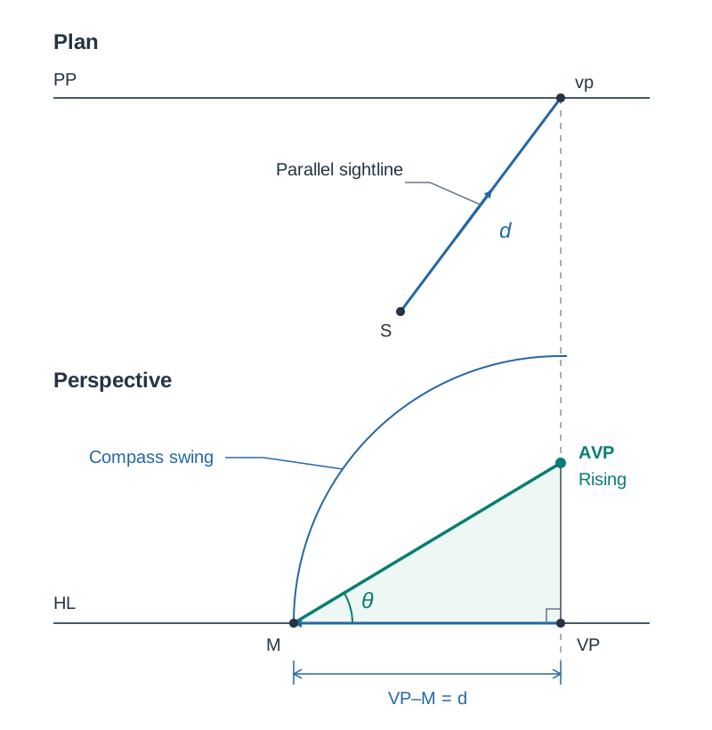
A vanishing point is the point where a sightline drawn through the spectator's eye, parallel to the set of lines in space, pierces the picture plane. For an inclined line, that sightline rises or falls at the true slope angle while travelling in the same plan direction. Therefore, it pierces the picture plane directly above or directly below the horizontal vanishing point of that direction. Point in the construction is simply the spectator's eye rotated (rebated) into the picture plane so that the true angle can be drawn on the flat sheet.
Direction rule
- Upward slopes: Lines that rise as they recede away from the spectator vanish to an AVP positioned above the horizon line.
- Downward slopes: Lines that fall as they recede away from the spectator vanish to an AVP positioned below the horizon line.
Finding the AVP — step by step
- Identify the horizontal vanishing point () for the plan direction of the sloping edges, and erect a vertical construction line through it.
- In plan, measure the true distance from spectator to the piercing point on the picture plane line ().
- In the perspective view, place your compass on and swing the measured distance onto the horizon line to locate rebatement point . (Swinging to either side of works).
- From point , draw a line at the true angle of inclination (taken directly from the orthographic elevation). Draw the line upwards if the roof rises as it recedes, or downwards if it falls. Where this line intersects the vertical construction line passing through , label the .
Checking your AVP by calculation
You can verify the position of the AVP using simple trigonometry:
where is the plan distance from to along the parallel sightline, and is the true angle of inclination. Marks in DCG are awarded for the visible compass swing and geometric construction; use this formula only as a quick check.
Curves and the Ordinate Method
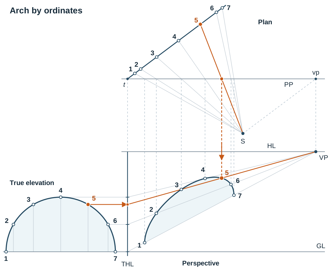
Circular profiles and curved surfaces viewed at an angle in perspective project as ellipses. Because visual rays converge towards the spectator, the closer half of a horizontal circle appears larger than the farther half. As a result, the geometric centre of the circle does not project to the centre of the perspective ellipse, meaning curves cannot be drawn with templates or compasses; they must be plotted point by point using ordinates.
Dividing the curve
Divide the curve in whichever orthographic view displays its true shape:
- Horizontal curves (circular bases, circular rims, curved ground walls): Divide the curve in plan into numbered intervals (for example, at or intervals using a set square). Take the vertical height of each point from the elevation.
- Vertical curves (arched doorways, semi-circular windows): Divide the curve in the elevation into numbered vertical ordinates, and project these positions down onto the plan.
Plotting the perspective points
- In plan, cast a visual ray from spectator to each numbered point on the curve, marking where each ray cuts the picture plane line.
- Establish a true height line by extending the plane containing the curve to touch the picture plane, or use an existing height line.
- Measure the true vertical height of each numbered point on the true height line, and vanish each height line back to the appropriate vanishing point.
- Drop vertical projectors from the picture plane piercing points to cross their corresponding receding height lines in the perspective view.
- Sketch a light, smooth curve through the plotted points, and darken the final visible profile. (Circles that lie directly parallel to the picture plane in one-point perspective do not distort into ellipses and can be drawn directly with a compass).
Finding the Angle of Elevation from the Spectator
Exam questions frequently conclude with a specific sub-question: "Determine the angle of elevation of the top of the mast/chimney from the spectator point S."
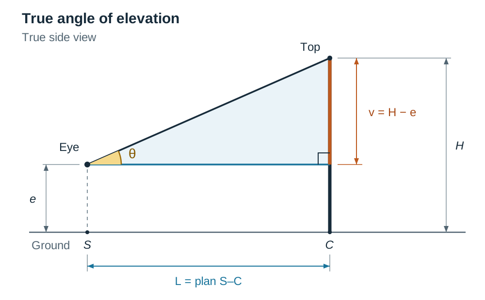
This angle is never measured directly off the perspective drawing. Because the perspective view is foreshortened, no vertical angle in it is true. Instead, you construct a true-length right-angled triangle representing the spectator's eye, the target point, and the ground.
Step-by-step graphical method
- In plan, draw a straight line connecting spectator point to the plan position of the point (such as the base of the mast at ). Measure this line with your scale rule. Because both and lie on the horizontal ground plane, this plan measurement gives the true horizontal distance () from spectator to element.
- Determine the vertical rise () from the spectator's eye level to the target point: subtract the height of the horizon line above the ground line from the true height of the point above the ground plane (). The horizon line represents the spectator's eye level, so subtracting it gives the vertical distance the viewer must look up.
- On a clear area of the drawing sheet, construct a right-angled triangle: draw horizontal base , erect vertical rise at one end at , and connect the hypotenuse back to .
- Measure the angle between the hypotenuse and the base line using a protractor. Label this angle clearly as the angle of elevation.
Mathematical calculation
You can verify your protractor reading with the formula:
If the target point sits below the horizon line, is negative, which gives an angle of depression.
Exam Strategy and 2027 Coursework Connection
Under the Leaving Certificate Assessment Arrangements, Section B of the written examination presents three core questions, from which candidates answer two (carrying 60 marks each). These three questions are chosen from four core syllabus topics: projection systems, conic sections, intersection and development of surfaces, and descriptive geometry of lines and planes. Because perspective is a regular projection systems question, a student who is secure on perspective has a strong candidate for one of the two Section B answers whenever a perspective question appears.
Perspective principles also link directly to the 2027 Higher Level Student Assignment brief, which focuses on a kettle design investigation and modification or concept design (160 marks total). Output 2 (freehand graphical representation of an existing kettle) and Output 6 (presentation of modification or concept design) each require high-quality rendered 3D presentation drawings. Applying accurate perspective principles — converging receding edges to consistent vanishing points and maintaining correct vertical foreshortening — ensures your freehand concept sketches look spatially convincing and professional.
Key terms
- Picture Plane (PP)
- The imaginary vertical plane positioned between the spectator and the object onto which the perspective view is projected; appears as a straight line in plan.
- Spectator Point (S)
- The exact position of the observer's eye in plan view looking towards the object.
- Horizon Line (HL)
- A horizontal reference line drawn in the perspective elevation at the spectator's eye level, containing all vanishing points for horizontal lines.
- Ground Line (GL)
- The horizontal baseline in the perspective elevation where the ground plane intersects the picture plane; all true vertical heights originate here.
- Vanishing Point (VP)
- A point on the horizon line where a set of parallel horizontal receding lines appears to converge in perspective.
- Auxiliary Vanishing Point (AVP)
- A vanishing point positioned on a vertical line directly above or below a primary horizontal vanishing point, used for sets of parallel inclined lines.
- True Height Line (THL)
- A vertical line on the picture plane where true elevations from the orthographic drawing can be measured directly at scale from the ground line.
- Visual Ray
- A straight sightline drawn from the spectator point S to a specific point on the object in plan, whose intersection with the picture plane locates that feature horizontally in the perspective elevation.
- Central Line of Vision
- The sightline from the spectator point S to the centre of the object in plan, perpendicular to which the picture plane is normally aligned to minimise visual distortion.
- Angular (Two-Point) Perspective
- A perspective projection system where the object's principal vertical faces are inclined to the picture plane, producing two vanishing points on the horizon line.
- Parallel (One-Point) Perspective
- A perspective projection system where one principal face is parallel to the picture plane, causing depth lines to converge to a single vanishing point (the centre of vision).
- Angle of Elevation
- The true angle between the horizontal line of sight from the spectator's eye and a line directed up to a specific elevated point on the object.
Check yourself
Where do all horizontal lines that are parallel to each other converge in an angular perspective drawing?
They converge at a single vanishing point located on the horizon line (HL).
How do you find the vanishing point in plan for any set of horizontal parallel edges?
Draw a line from the spectator point S parallel to those edges in plan until it intersects the picture plane line.
Under what condition can a vertical height from an orthographic elevation be marked directly at full scale in the perspective view?
Only when measured along a True Height Line on the picture plane where a surface or corner touches the picture plane at the ground line.
A ramp surface descends at an angle of 18° as it recedes away from the spectator. Where is its auxiliary vanishing point positioned?
On the vertical line passing directly through the horizontal vanishing point of its plan direction, positioned below the horizon line.
The horizon line is 3.0 m above the ground line and a flagpole top is 7.5 m above ground. The plan distance from spectator S to the pole measures 160 mm at a scale of 1:100. Find the angle of elevation of the top of the pole from S.
True distance L = 160 mm * 100 = 16 000 mm = 16 m. Vertical rise above eye level v = 7.5 m - 3.0 m = 4.5 m. tan(theta) = 4.5 / 16 = 0.281, giving theta = tan^-1(0.281) = 15.7°.
A chimney stands 5 m behind the front wall of a house and does not touch the picture plane. How do you establish its true height in perspective?
In plan, draw a line through the chimney parallel to one of the house's principal directions forward to the picture plane; drop that contact point to the ground line to create a height line; measure the true height there and vanish both the base and top marks back to that direction's vanishing point to cross the chimney's vertical projector.
Why does a horizontal circle project as an ellipse whose centre does not coincide with the perspective centre of the circle?
Because the circle is not parallel to the picture plane, its perspective image is an ellipse. The near half of the circle is closer to the spectator and so appears larger than the far half, which means the centre of the circle does not project to the centre of the ellipse — the curve must be plotted point by point with ordinates rather than drawn with a template.