
Orthographic and auxiliary projection forms the core graphic language of Leaving Certificate Design & Communication Graphics. At Higher Level, students must move fluently between three-dimensional spatial concepts and two-dimensional orthographic drawings: establishing principal planes of reference, projecting first and subsequent auxiliary views, determining true lengths of lines and true shapes of surfaces, resolving dihedral angles, handling oblique solids, cutting solids with inclined and oblique section planes, calculating solids in mutual contact, and constructing the geometry and spherical centres of the regular cube and tetrahedron. Under the 2027 examination arrangements, the 3-hour written examination (60%, 240 marks) requires answering three questions from Section A (20 marks each), two from Section B (60 marks each), and one option question from Section C (60 marks). The accompanying 160-mark Student Assignment brief investigates a household kettle, requiring precise orthographic, sectional, and detail views across portfolio outputs.
Reference Planes, Projection Systems, and Technical Conventions
Orthographic projection maps 3D forms onto flat surfaces using parallel projectors that hit the projection planes at right angles (). Space is bounded by three mutually perpendicular surfaces known as the principal planes of reference: the Horizontal Plane (HP), the Vertical Plane (VP), and the End Vertical Plane (EVP).
The ground line, labelled the XY line, marks where the VP intersects the HP. Where a question is built from the principal planes, or where you set up any auxiliary view, show and label the reference lines: XY, , . Marks are awarded for the correct set-up of reference lines and for measurements transferred from them, so an unlabelled auxiliary line costs you the points that depend on it. If an examination question provides two views without a ground line and no auxiliary projection is required, you do not need to invent one.
The XY line performs four roles:
- It represents the physical intersection of the VP and the HP.
- It acts as the hinge axis around which the HP rotates downwards into coincidence with the VP.
- Looking straight down in plan, the XY line is the edge view of the VP.
- Looking horizontally in front elevation, the XY line is the edge view of the HP.
First-Angle versus Third-Angle Conventions
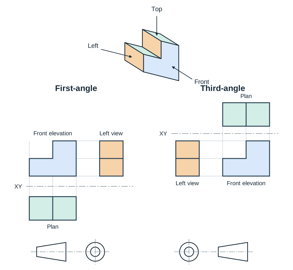
In first-angle projection (the standard European convention used across the Leaving Certificate core), the object sits in the first quadrant, between the observer and the plane of projection:
- The elevation (front view) projects onto the VP and sits above the XY line.
- The plan (top view) projects onto the HP and rotates down directly beneath the elevation, below the XY line.
- An end view viewed from the left of the object is drawn on the right-hand side of the front elevation.
In third-angle projection (standard in CAD software such as SolidWorks and examinable at Higher Level), the projection plane sits between the observer and the object:
- The plan sits directly above the elevation, above the XY line.
- The elevation sits below the plan, beneath the XY line.
- An end view viewed from the left is drawn on the left-hand side of the elevation.
The projection symbol is a truncated cone: in first angle, the trapezium (front view of the cone) is on the left and the concentric circles (its end view) are on the right; in third angle, the concentric circles are on the left and the trapezium is on the right.
Conventions to Apply on Every Drawing
- Visible outlines: thick continuous lines.
- Hidden edges: thin dashed lines.
- Centre lines and axes: thin chain lines (long dash, short dash).
- Construction and projection lines: thin continuous lines, left on the sheet lightly so the examiner can follow your method.
- Reference lines: labelled thin chain lines (XY, , ).
- Cutting planes: thin chain lines with thick short terminations and changes of direction, with arrows indicating the viewing direction and letters at each end (e.g. A–A).
- Hatching: thin continuous lines, evenly spaced, at to the main outline. Where two cut components touch, reverse the hatching angle or change the spacing. Never hatch empty space.
- Scale: if a scale is specified (e.g. 1:2 or 1:200), write the scale on your sheet and convert every given linear dimension before drawing. Angles are never scaled.
First and Subsequent Auxiliary Projections and the Visibility Rule
When an edge or surface slopes relative to the principal planes, its dimensions appear foreshortened in standard views. An auxiliary view projects the object onto an auxiliary plane set at a chosen angle, established by a new reference line ().
- Auxiliary elevation: Projected from the plan across an line. Projectors run strictly perpendicular to . Heights are transferred from the front elevation, measured vertically from the original XY line.
- Auxiliary plan: Projected from the front elevation across an line. Projectors run strictly perpendicular to . Depths are transferred from the plan, measured perpendicularly from the original XY line.
The Two-View Rule
When projecting into any auxiliary view, skip the adjacent view you are projecting from, and transfer measurements from the view immediately preceding it. For a first auxiliary elevation projected from plan, take heights from the elevation. For a second auxiliary view () projected from that auxiliary elevation, measure the perpendicular distances from each point in the plan view back to the line, and step off these exact distances along the projectors from .
The Visibility Rule
In any projected view, the observer looks perpendicular to the ground line from the side the object is on:
- In plan, the observer looks from above: the point with the greatest height in elevation is nearest, so edges meeting it are visible.
- In elevation, the observer looks from the front, with the object between the observer and the VP: the point with the greatest distance from XY in plan (that is, furthest in front of the VP) is nearest the observer, so edges meeting it are visible; the point closest to XY in plan is furthest away and its edges are hidden.
- In an auxiliary view, look back at the view you projected from: points lying furthest from on the object's side are nearest to the observer and are visible (thick continuous lines); points closest to are furthest away and their edges are hidden (thin dashed lines). Where visible and hidden lines coincide, draw the visible line.
Lines and Planes in Space: True Lengths, Inclinations, Edge Views, and True Shapes
A line only appears in true length in a view where the line is parallel to the plane of that view:
- If the plan of a line is parallel to XY, the line is parallel to the VP and its elevation is a true length; the angle it makes with XY is its true inclination to the HP ().
- If the elevation is parallel to XY, the line is parallel to the HP and its plan is a true length; the angle it makes with XY is its true inclination to the VP ().
- If neither view is parallel to XY, the line is inclined to both planes and neither standard view shows its true length.
Finding True Length and Inclination from Given Views
- Method 1 – Auxiliary Projection: Draw parallel to the plan of the line. Project perpendicular to and take heights from the elevation. The auxiliary elevation reveals the true length of the line, and the angle it forms with is (inclination to HP). Alternatively, drawing parallel to the elevation and taking depths from plan produces an auxiliary plan showing true length and (inclination to VP).
- Method 2 – Rotation: Rotate the plan of the line about one end until it is parallel to XY. The rotating point swings in an arc while its distance from the VP equalises. Project this rotated end vertically up to its own height locus in elevation and connect to the pivot. The resulting line in elevation is the true length, and its angle to XY is .
Determining Projections Given Angles of Inclination (Higher Level Only)
When a line of true length is given with its inclination to the HP and to the VP:
- In elevation, draw a line from at angle to the XY line and mark true length along it. Its horizontal length gives the plan length () and its vertical rise gives the height difference (). Draw a horizontal height locus at above .
- In plan, draw a line from at angle to the XY line and mark true length along it. Its perpendicular distance from XY gives the depth difference () and its horizontal extent parallel to XY gives the elevation length (). Draw a horizontal depth locus at distance from .
- Swing an arc of radius equal to the plan length () about in plan to intersect the depth locus at distance : this establishes .
- Swing an arc of radius equal to the elevation length () about in elevation to intersect the height locus at : this establishes .
- Verify that and align vertically on the exact same projector.
Example: For , , and :
- Plan length ; height difference .
- Elevation length ; depth difference .
What Fixes a Plane in Space
A plane is a flat surface of unlimited extent, fixed by any one of the following:
- Three points not in a straight line (non-collinear).
- A line and a point not on that line.
- Two intersecting lines.
- Two parallel lines.
In examination questions, a plane is typically presented as a polygonal figure (e.g. triangle ABC given by coordinates), by its traces (horizontal trace (HT) and vertical trace (VT), written as plane VTH), or by a line on the plane combined with an inclination angle. The HT and VT meet at a point on the XY line, unless the plane is parallel to the XY line, in which case both traces run parallel to XY.
Edge View and True Shape of an Oblique Surface
A plane surface only displays its true shape when viewed square-on. To achieve this, you must first construct an edge view, where the plane collapses into a single straight line. A plane appears as an edge when viewed along any line that lies on the plane and appears in true length. The most reliable line to use is a horizontal line on the plane, often called a strike line.
Steps for a surface ABC given in plan and elevation:
- In elevation, draw a horizontal line at a convenient height crossing two edges of the surface, say cutting at and at .
- Project and down to the corresponding edges in plan to locate and . Because this line is horizontal in space, in plan is in true length.
- Set up a first auxiliary ground line perpendicular to in plan. Project all vertices perpendicular to and transfer their vertical heights from elevation (measured from XY). In this auxiliary elevation, the surface collapses into a single straight line: the edge view.
- The angle this edge view makes with is the true inclination of the plane to the HP.
- Draw a second auxiliary ground line parallel to the edge view. Project all points perpendicular to , and transfer the perpendicular distances of each point from in the plan view. Joining these points gives the true shape of ABC.
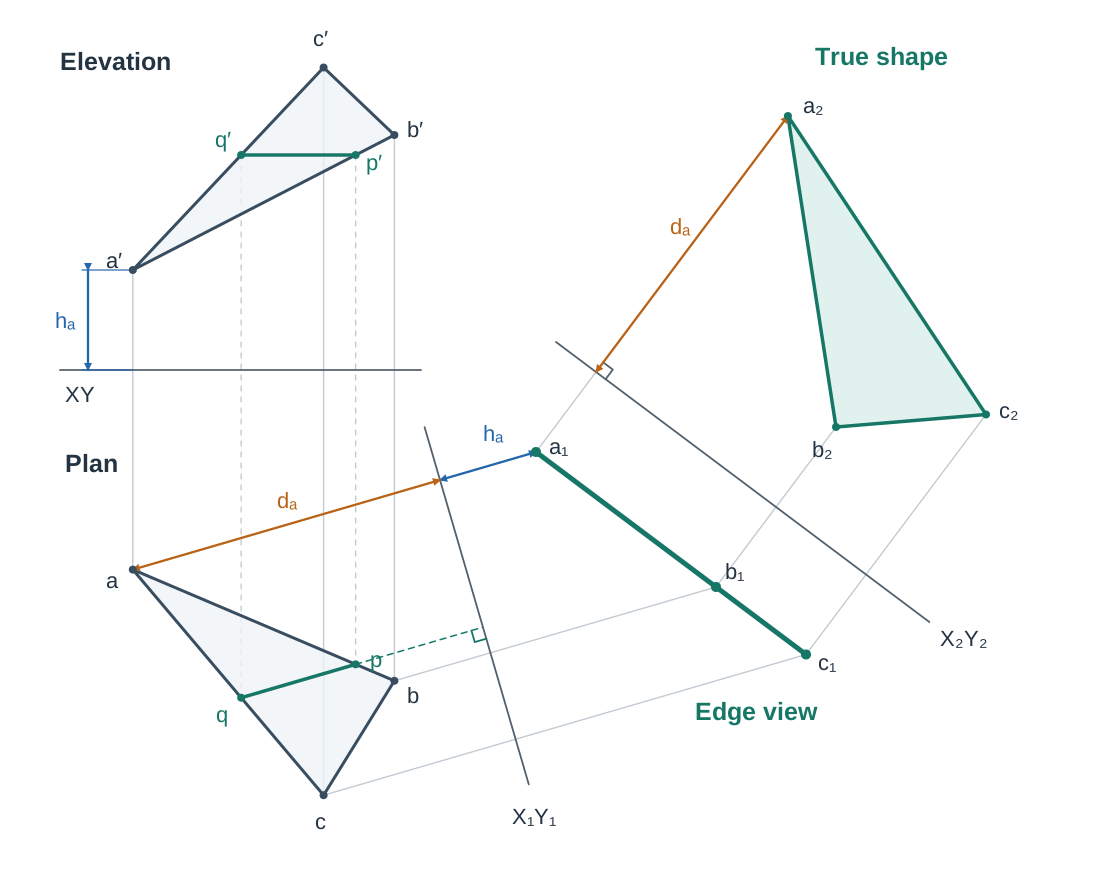
If the surface is given by traces VTH, an auxiliary elevation looking along the HT (with perpendicular to HT) gives the edge view directly. Alternatively, you may rebate (swing) the plane around HT into the HP; the rebated figure is the true shape.
Dihedral Angles and Slicing Solids with Section Planes
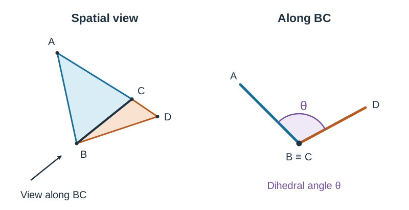
The true angle between two intersecting planar surfaces is their dihedral angle. To see it, you must look directly along their shared line of intersection so that the line appears as a point and both planes appear as edges.
The Two-Auxiliary Dihedral Sequence
- First Auxiliary (): Draw parallel to the plan of the intersection line. Project perpendicular to and take heights from the elevation. The line of intersection now shows in true length.
- Second Auxiliary (): Draw perpendicular to that true-length line. Project along the line (perpendicular to ). Transfer distances measured from back to the plan points. In this second auxiliary view, the shared edge appears as a point, the two surfaces appear as straight lines, and the measured angle between them is the dihedral angle.
Section Planes
A section plane cuts through a solid to expose internal detail:
- Simply inclined plane: Inclined to one principal reference plane and perpendicular to the other. When perpendicular to the VP and inclined to the HP, it appears as a straight inclined edge line in elevation. Cut points on solid edges are projected vertically down to plan.
- Oblique plane: Inclined to both HP and VP, showing as an edge in neither standard view. To cut a solid with an oblique plane given by traces VTH, set perpendicular to HT in plan to produce an auxiliary elevation where the plane appears as an edge. Project the solid into this view, mark the cut points on the edges, and project them back to plan and elevation.
- Horizontal helping planes: Slice horizontally across elevation at height . This cutting plane intersects the VT at point . Project down to the XY line in plan, and draw a line parallel to HT. Where this line intersects the solid's cross-section at height gives points on the cut surface.
Tilting Right Solids and Projecting Oblique Solids
'Right' describes the internal geometry between the central axis and the base of a solid (the axis is perpendicular to the base), not its position on the page. A right cylinder or right cone remains a right solid even when tilted.
The Tilt-and-Turn Method for Right Solids
To position a right solid so that a face or edge rests on a principal plane:
- Simple position: Draw the solid resting flat on the HP, orienting it so the target face or edge appears as an edge line in elevation (e.g. keeping its base edge perpendicular to the VP).
- Tilt: Redraw the elevation as an exact copy of itself, rotated about the base pivot until the chosen face or edge lies along the XY line. The elevation keeps its shape and all its internal dimensions, but every point's height above XY and its horizontal position on the page change with the rotation. Nothing is copied across from the old elevation except the shape itself; the depths for the new plan come from the original plan (step 3).
- Project new plan: Drop vertical projectors from the tilted elevation and carry across depths from the original plan.
- Turn (if required): If the solid's axis must also lie at an angle to the VP, rotate the new plan to that angle and project a third elevation, taking heights from the tilted elevation.
Oblique Solids (Higher Level Limitation)
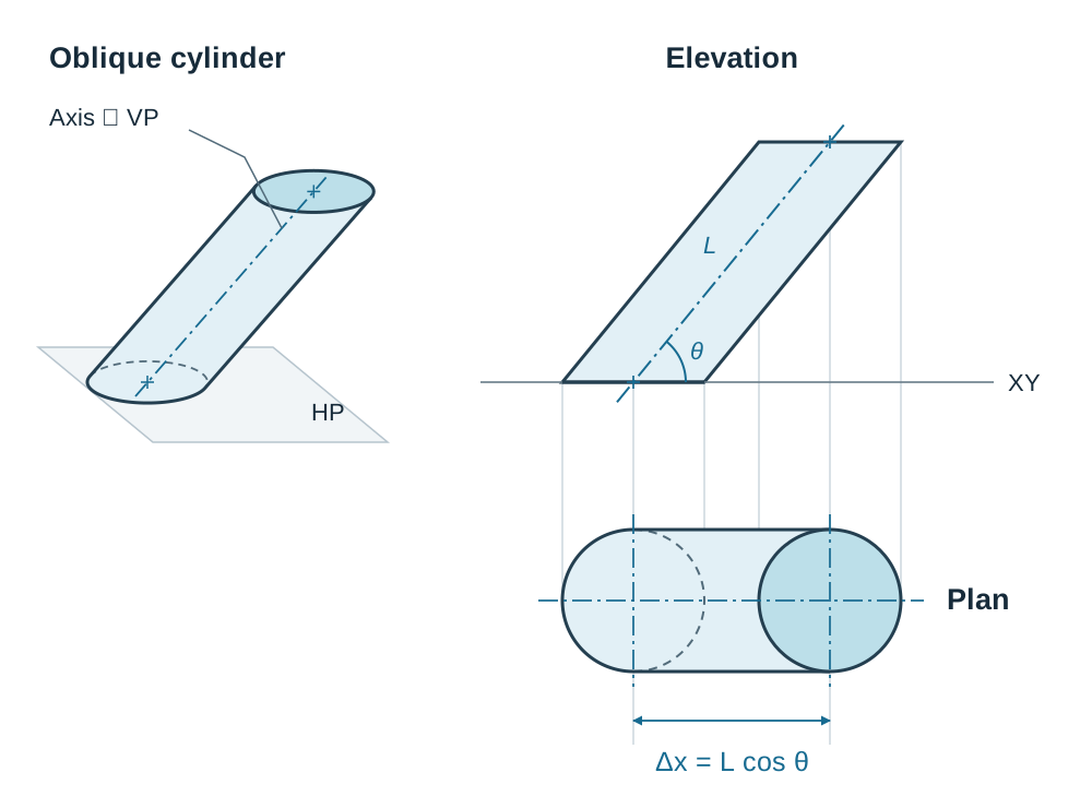
An oblique solid has its central axis inclined to its base, like a stack of coins slid sideways. The Leaving Certificate Higher Level syllabus strictly restricts oblique solids to those whose axis is inclined to one principal reference plane only.
- Oblique cylinder (base on HP, axis inclined to HP and parallel to VP): The circular base and top both lie in horizontal planes, meaning they project as true circles in plan. In elevation, the axis slopes at its true angle to XY, and top and bottom appear as horizontal lines. In plan, draw the base circle and offset the top circle horizontally by the axis run (, where is the true length of the axis and is its inclination to the HP). Connect the circles with common exterior tangents to complete the plan.
- Oblique cone: In plan, the base is a true circle and the apex is offset sideways. The plan outline is completed by drawing tangent lines from the apex plan to the base circle.
Solids in Mutual Contact
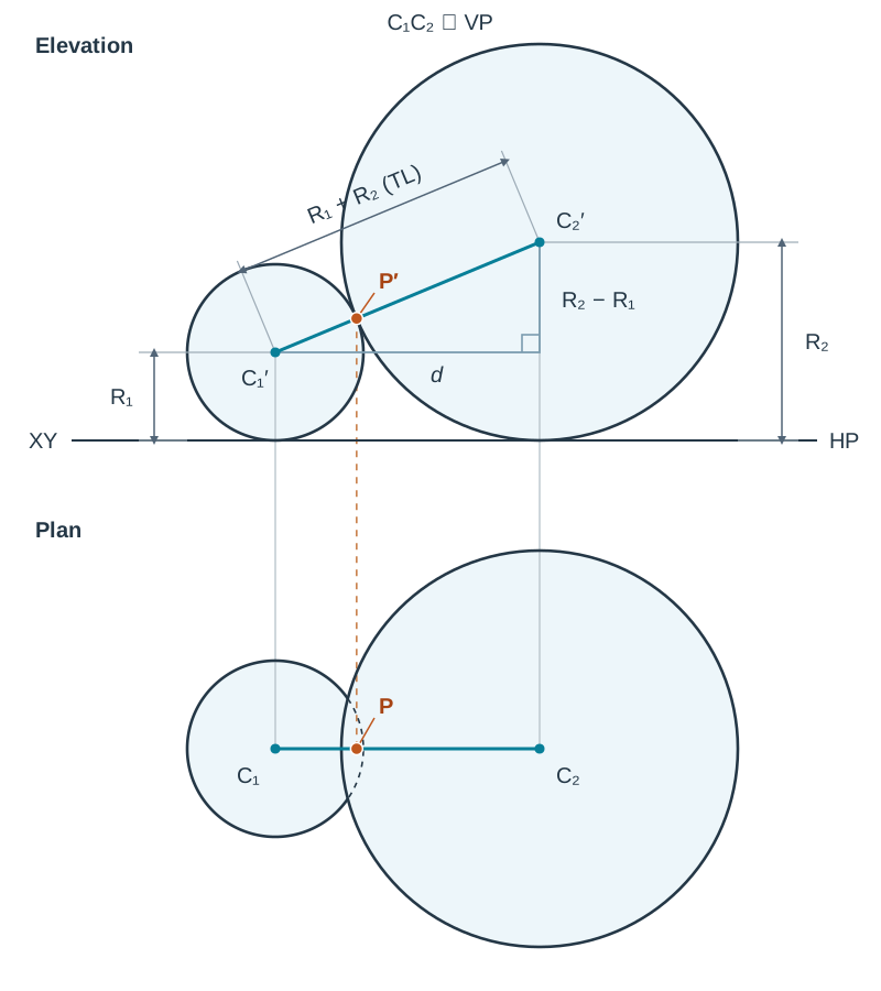
When spheres, cones, and planes touch without penetrating, their positions must be determined through exact contact geometry. Marking schemes credit the point of contact separately from the position of the solid, and expect to see it shown in both plan and elevation.
The Principle of Contact Geometry
For two touching spheres, the distance between their centres in 3D space is , which is a true length. This distance only appears at full size in a view where the line of centres is parallel to the projection plane:
- If both spheres rest on the HP, their centres sit at heights and above XY. The line of centres is not horizontal unless . The horizontal plan distance between centres must be calculated using Pythagoras' theorem or constructed graphically:
- The point of contact lies on the line of centres in both views, dividing the line in the ratio .
Three Solids in Contact
To position a third sphere touching two known spheres that already rest on the HP:
- Calculate the plan distance from each known sphere centre to the new centre: and .
- In plan, swing arcs of radius and from the respective sphere centres; their intersection fixes the plan of the third centre.
- Project vertically to elevation at height above the XY line.
Sphere Touching a Right Cone
In an elevation showing the true triangular profile of a right cone on the HP, a touching sphere appears as a circle tangent to the cone's extreme generator. Construct a line parallel to the generator, offset outward by perpendicular distance . The intersection of this offset line with the sphere's height locus fixes the sphere centre in elevation. A normal drawn from the sphere centre perpendicular to the generator locates the point of contact in elevation.
If the sphere touches at an arbitrary position around the cone, its centre in plan traces a circle centred on the plan of the cone's axis (for a right cone on the HP, this is the plan of the apex), with radius equal to the horizontal distance from the axis to the sphere centre. Rotate the point of contact back to plan using a concentric arc.
Geometry of the Regular Cube and Tetrahedron
The regular cube and regular tetrahedron are Platonic solids with fixed geometric relationships.
The Regular Cube
- Edge length , face diagonal , long body diagonal .
- Incentre and circumcentre coincide at the midpoint of the body diagonals.
- Inscribed sphere touches all 6 face centres: radius .
- Circumscribed sphere passes through all 8 vertices: radius .
The Regular Tetrahedron
- Composed of 4 congruent equilateral triangular faces of edge length .
- A regular tetrahedron can be inscribed in a cube by joining alternating vertices; each edge of the tetrahedron is a face diagonal of the cube ().
- Vertical altitude (): In a right triangle formed by an edge as hypotenuse and the distance from a base vertex to the base centroid () as base:
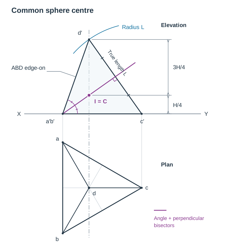
- Incentre and Circumcentre: Both centres coincide at a single point on the central vertical axis at height above the base ( below the apex):
SEC Graphical Construction for Tetrahedron Sphere Centres
- Draw the plan of the tetrahedron resting on the HP as an equilateral triangle with edge perpendicular to XY. Apex projects to the centroid.
- In elevation, and coincide on XY, and lies on XY. Face ABD appears as an edge line . Edge DC is parallel to the VP, so shows in true length (). Find apex by swinging an arc of radius from to intersect the vertical axis line drawn through .
- Incentre: Bisect the angle between the ground line (XY) and the edge view line . Where this bisector crosses the vertical axis is the incentre.
- Circumcentre: Construct the perpendicular bisector of the true-length edge . It intersects the vertical axis at the exact same point as the incentre, confirming the construction.
Examination Strategy, Timing, and 2027 Coursework Integration
Leaving Certificate Higher Level DCG is assessed through a 3-hour terminal examination (60%, 240 marks) and a Student Assignment (40%, 160 marks).
Time Management in the 3-Hour Exam
- Section A (Core): Answer 3 of 4 questions (20 marks each). Spend 45 minutes total (15 minutes per question).
- Section B (Core): Answer 2 of 3 questions (60 marks each). Spend 90 minutes total (45 minutes per question).
- Section C (Options): Answer 1 of 5 questions (60 marks). Spend 40 minutes.
- Final Check: 5 minutes to verify linework weight, ensure every reference line is labelled (XY, , ), and confirm all requested true lengths, angles, and points of contact are clearly annotated.
Strategic note on options: Although the adjusted 2027 examination paper requires answering only one Section C question, the syllabus framework specifies that two option areas must be studied. Maintaining both options gives you a valuable choice on exam day if one question presents an awkward setup.
2027 Student Assignment Integration (Kettle Brief)
The Higher Level coursework requires a design investigation and modification or concept design of a household kettle (maximum 10 A3 pages, 5 to 10 SolidWorks parts, submission deadline: Friday 15 January 2027):
- Original Sketches: You must submit your original freehand sketches for Outputs 2 and 6. Scanned copies will not be accepted.
- USB Filing Structure: Marks are allocated for correct file naming. The USB drive must contain one main folder named
DCG SA 2027(Exam number). Inside, include one sub-folder containing the complete portfolio in PDF format, and a second sub-folder containing two separate sub-folders for the Part A and Part B SolidWorks files. - Output 4 (Hardcopies of Existing Artefact): Requires orthographic views, an exploded view, a rendered pictorial view, and section/detail views.
- Output 7 (Hardcopies of Concept/Modified Design): Requires orthographic views, a rendered pictorial view, a section/detail view, and a photorealistic view, plus the electronic CAD files. (Note: the stand-alone photorealistic output was removed under the adjustments, but a photorealistic view is still required within Output 7).
Key terms
- XY line
- The ground line formed by the intersection of the Vertical Plane and Horizontal Plane, acting as the hinge line between elevation and plan views.
- principal planes of reference
- The three mutually perpendicular surfaces (Horizontal Plane, Vertical Plane, and End Vertical Plane) onto which orthographic views are projected.
- first-angle projection
- An orthographic arrangement where the object sits between the observer and the projection planes, placing the plan view directly beneath the front elevation.
- third-angle projection
- An orthographic arrangement where the projection plane sits between the observer and the object, placing the plan view directly above the front elevation.
- auxiliary elevation
- A view projected from the plan onto a vertical plane set at an angle to the VP, using an X1Y1 ground line and heights transferred from the front elevation.
- auxiliary plan
- A view projected from the front elevation onto an inclined plane, using an X1Y1 ground line and depths transferred from the plan view.
- true length
- The actual full-scale length of a line in space, seen only when viewing perpendicular to the line or when the line is parallel to the plane of projection.
- edge view
- A projection in which a flat surface collapses into a single straight line, obtained by viewing parallel to a true-length line lying on that surface.
- true shape
- The actual undistorted shape of a planar surface, obtained by viewing strictly perpendicular to its edge view.
- dihedral angle
- The true internal angle between two intersecting planar faces, visible only in a view where their shared line of intersection appears as a point.
- simply inclined plane
- A cutting plane that is inclined to one principal reference plane and perpendicular to the other, appearing as an edge line in one standard view.
- oblique plane
- A plane inclined to both the Horizontal Plane and the Vertical Plane, showing no edge view in standard plan or elevation.
- horizontal trace
- The line along which an inclined or oblique plane intersects the Horizontal Plane (abbreviated HT).
- vertical trace
- The line along which an inclined or oblique plane intersects the Vertical Plane (abbreviated VT).
- oblique solid
- A solid whose central axis is inclined to its base. In Leaving Certificate DCG, projection is limited to axes inclined to one principal reference plane only.
- generator
- A straight line lying on the curved surface of a cone or cylinder connecting its base boundary to its apex or opposite rim.
- point of contact
- The precise geometric point at which two curved surfaces, or a curved surface and a plane, touch without intersecting.
- incentre
- The centre of an inscribed sphere that touches all faces of a polyhedron from the inside, equidistant from each face.
- circumcentre
- The centre of a circumscribed sphere that passes through every vertex of a polyhedron, equidistant from each vertex.
Check yourself
What four distinct geometric functions does the XY line perform in orthographic projection?
It marks the intersection of the HP and VP, acts as the hinge line around which the HP rotates, represents the edge view of the VP in plan, and represents the edge view of the HP in front elevation.
In third-angle projection, where are the plan and the left end view positioned relative to the front elevation?
The plan is positioned directly above the front elevation, and the left end view is drawn on the left-hand side of the front elevation.
A triangle ABC is given in plan and elevation, sloping to both principal planes. State the two auxiliary views needed to find its true shape and what each one achieves.
First auxiliary (X1Y1 perpendicular to the plan of a horizontal strike line on ABC) produces an edge view of the triangle. Second auxiliary (X2Y2 parallel to that edge view) reveals the true shape of ABC.
The plan of a line is 80 mm long and its ends differ in height by 60 mm in elevation. Calculate its true length and inclination to the HP.
True length = sqrt(80² + 60²) = sqrt(6400 + 3600) = sqrt(10000) = 100 mm. Inclination to HP: tan θ = 60/80 = 0.75, so θ = 36.87° (approx. 37°).
What are the two auxiliary view stages required to determine the true dihedral angle between two intersecting planes?
Stage 1: Project an auxiliary view parallel to the line of intersection to see it in true length. Stage 2: Project a second auxiliary view perpendicular to that true-length line to see the intersection line as a point and both planes as edge lines.
How do the circular top and base of an oblique cylinder (axis inclined to HP, parallel to VP) project in the plan view?
They project as two identical true circles, offset horizontally by the run of the axis and connected by two common exterior tangent lines.
For a regular tetrahedron of vertical altitude H, where along its vertical axis do the incentre and circumcentre lie?
Both centres coincide at a single point located at a height of 1/4 H above the base (or 3/4 H below the apex).
Two spheres with radii 25 mm and 15 mm rest on the HP in mutual contact. What is the true spatial distance between their centres, and what is the horizontal distance between their centres in plan?
True spatial distance = R1 + R2 = 25 + 15 = 40 mm. Height difference = 25 - 15 = 10 mm. Horizontal plan distance = sqrt(40² - 10²) = sqrt(1600 - 100) = sqrt(1500) ≈ 38.73 mm.