
In descriptive geometry, laminar plane problems examine how thin, flat surfaces are oriented, positioned, and intersect in three-dimensional space. A lamina is a flat surface with negligible thickness, bounded by straight edges, typically defined by spatial coordinates [x, y, z] of its vertices. When two non-parallel laminae meet, their planes intersect along a straight line of intersection (LOI) and form an opening known as the dihedral angle. Solving these problems relies on two geometric building blocks: viewing a true length line end-on turns it into a point view, and viewing any line lying on a plane as a point view turns the entire plane into an edge view.
1. Laminar Surfaces, Coordinates, and Plane Classification
A lamina is a flat surface with negligible thickness, bounded by straight edges, like a thin sheet of metal or a pane of glass. In Leaving Certificate DCG questions, laminae are usually triangular or quadrilateral, with vertices defined by Cartesian coordinates in the format :
- -coordinate: Horizontal distance from the left-hand datum along the ground line (). It is identical in plan and elevation.
- -coordinate: Distance in front of the Vertical Plane (VP). In first-angle projection, measure this downward from the line to locate the plan view.
- -coordinate: Height above the Horizontal Plane (HP). Measure this upward from the line to locate the elevation view.
Always plot and label every vertex slowly in both views ( in plan and in elevation). A plotting error of even 1 mm propagates into every auxiliary projection.
Simply Inclined or Obliquely Inclined?
Before projecting anything, inspect the given views:
- A simply inclined plane is perpendicular to one principal plane of reference and inclined to the other. It already appears as a single straight line—an edge view—in either plan or elevation. Its inclination can be measured directly in that view with a protractor, and its true shape requires only one auxiliary view, projected parallel to the existing edge view.
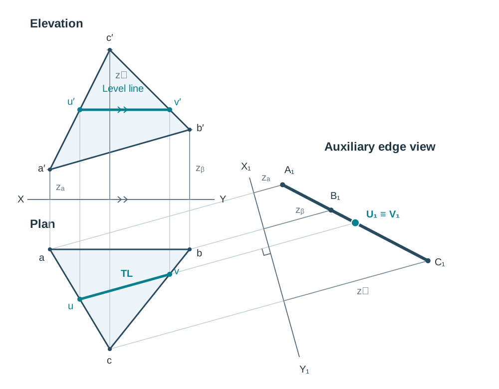
- An obliquely inclined plane is inclined to both the HP and the VP. It appears foreshortened as an area in both plan and elevation. To find its edge view, you must first construct a line of true length lying on the plane, look along it to get a point view, and then project a second auxiliary view to find its true shape.
2. True Length, True Inclination of Lines, and Edge Views
A line only shows its true length () in an orthographic view if your line of sight is perpendicular to it, meaning the line must be parallel to the plane of projection.
True Inclination of a Line
When you project a line to find its true length, you also find its true inclination:
- Inclination to the HP (): Draw parallel to the plan of the line. Project both ends perpendicular to and transfer their vertical heights () from elevation. The angle between the true length line and is .
- Inclination to the VP (): Draw parallel to the elevation of the line. Project both ends and transfer their plan depths () from the line. The angle between the true length line and is .
- Rotation Method: Alternatively, rotate the line in plan about one end until it is parallel to , then project the rotated end vertically to elevation at its original height. The angle between this new elevation and is . Rotating in elevation until parallel to and projecting to plan gives .
Sanity check: For any straight line, . If your measured angles sum to more than , check your projections.
Level Lines and Frontal Lines on a Plane
To find an edge view of an oblique plane, you must introduce a line on the plane that is already in true length:
- Horizontal line on the plane (level line): In elevation, draw a horizontal line across the plane parallel to . Where this line crosses the edges of the lamina, project vertically down to the matching edges in plan. This line in plan is in true length (often called a strike line in mining geometry).
- Frontal line: In plan, draw a line across the lamina parallel to . Project the cut points vertically up to elevation. In elevation, this line appears in true length.
(Note on examination practice: All points along edges must be located graphically by projection between views. The linear fraction is only a calculation check for your plotted positions; Leaving Certificate examiners award marks for construction lines, not arithmetic formulas.)
3. Determining the Line of Intersection (LOI)
The planes of two non-parallel laminae always meet in a straight line. The laminae themselves only touch along the part of that line that lies inside both of them, so the line you draw is a segment, not an endless line. Only the part of the line lying inside both laminae actually exists—draw that portion as a continuous line and stop it at the boundary of the smaller overlap.
Case 1: Shared Named Vertices
When two laminae share two lettered vertices (such as and ), the edge joining them () is already the line of intersection. No cutting planes are needed; line in plan and in elevation is the complete LOI.
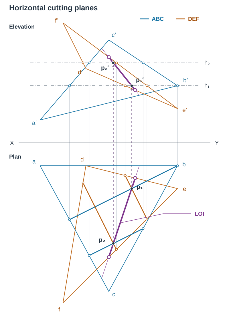
Case 2: Crossing Laminae (Horizontal Cutting Plane Method)
When two separate planes cross each other without shared vertices (such as and ):
- In elevation, draw a horizontal cutting line across both laminae at a convenient height (often through an existing vertex). Where this line cuts the edges of , project vertically down to the matching edges in plan and join them. Do the same for .
- In plan, find where these two cut lines intersect. This crossing point lies on both planes at height . Project vertically back to the cutting line in elevation to locate .
- Repeat the exact process with a second cutting plane at a different height to find the second common point ( in plan, in elevation).
- Connect and in plan and elevation, stopping the segment where it exits either lamina.
Lines of Intersection from Traces
When planes are defined by traces, where the two horizontal traces () cross is a point on the LOI that lies on the HP (its plan is the crossing, its elevation is on ). Where the two vertical traces () cross is a second point lying on the VP (its elevation is the crossing, its plan is on ). Connect the two points in both views.
Visibility
Where two laminae interpenetrate, surface visibility swaps on either side of the line of intersection—test one apparent crossing by projecting to the adjacent view, and the rest follow. Where two laminae only share a common edge (as in and ), there is no interpenetration: decide visibility once by comparing the heights of the outer vertices in elevation, or their depths in plan.
4. Constructing the Dihedral Angle
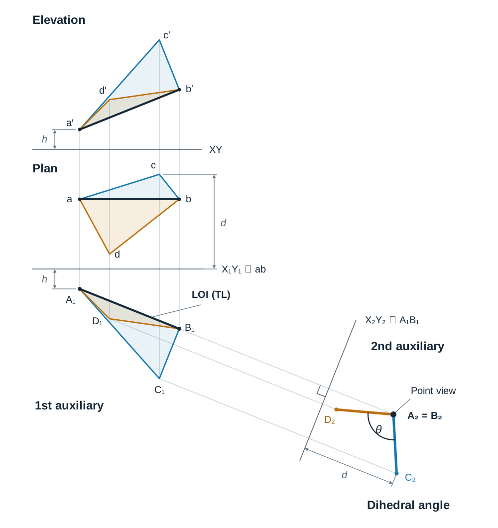
The dihedral angle between two planes is the angle between them measured in a plane perpendicular to their line of intersection. Visualise looking straight down the spine of an open book: only when the spine is viewed end-on as a point do both covers appear as clean edges, revealing the true opening angle.
Step-by-Step Construction
- First Auxiliary View (): Draw parallel to the plan of the line of intersection. Project all vertices of both laminae perpendicular to . Measure the vertical height () of each point from in elevation, and transfer these heights from . The line of intersection is now shown in true length.
- Second Auxiliary View (): Draw datum line perpendicular to the true length line. Project all points parallel to the true length line across .
- Transfer Measurements: Measure distances from two views back: take the perpendicular distance from the line back to each vertex in the plan view, and step that distance from along the corresponding projector.
- Point View and Edge Views: Both ends of the line of intersection will land on the exact same location, forming a point view. The outer vertices project as single points. Join each outer point to the point view to form two straight lines (edge views). Measure the included angle with a protractor, draw an arc, and state the value in degrees.
Always make a quick freehand 3D sketch before starting. It takes twenty seconds and clarifies whether the acute or obtuse opening represents the true physical dihedral angle.
Try-It Construction Check
Planes and share edge . Coordinates (mm): , , , . Spine of solution: Draw plan and elevation. True length of . Set parallel to , transfer heights from elevation (). Set perpendicular to , transfer perpendicular distances from back to plan. Vertices and merge into a single point view . Joining and to the point view produces a dihedral angle of (supplementary angle ).
5. True Angle Between Lines, True Shape, and Rebatement
True Angle Between Two Intersecting Lines
Two lines that meet define a plane, and the angle between them is only seen in the true shape of that plane. If asked for the angle between lines and :
- Join the free ends and in plan and elevation to complete triangle .
- Draw a horizontal line on in elevation, project to plan to get its true length, and set perpendicular to that line in plan to obtain the edge view.
- Draw parallel to the edge view and project the true shape of , transferring distances from plan measured perpendicular to .
- Measure the angle at directly with a protractor. (Do not confuse this with a dihedral angle: a dihedral angle requires a point view of an edge, whereas the angle between two lines requires a true shape of their containing surface.)
True Shape: Rebatement Method
An inclined plane can also be revolved flat onto the HP about its horizontal trace () or about a level line:
- Each vertex rotates in a plane perpendicular to the axis of rotation, so in plan it travels along a line perpendicular to the .
- Drop a perpendicular from the vertex in plan to the , meeting it at foot .
- The radius of rotation is the true distance from the vertex to the axis: construct a right-angled triangle whose base is the plan distance from the vertex to and whose height is the vertex's height above the HP. The hypotenuse is the true distance.
- Centring your compass at , swing that hypotenuse along the perpendicular to locate the rebatted vertex. Repeat for all vertices and join them to obtain the true shape.
Locating a Point at a Given True Distance Along an Edge
When a point lies at a specified true distance along an inclined edge :
- Project an auxiliary view parallel to in plan to show in true length.
- Measure the true distance along the line from to fix point .
- Project perpendicularly back to edge in plan to locate , and vertically up to edge in elevation to locate . Check that and lie on the same vertical projector.
6. Summary Decision Table and Drawing Discipline
Every problem in descriptive geometry comes down to identifying which line must be seen in true length, where to place the reference axis, and where to measure from.
| Desired Quantity | Line Needed in True Length | Position of | Subsequent Step |
|---|---|---|---|
| Dihedral angle | Line of intersection | Parallel to plan of LOI | perpendicular to line point view and edge views |
| Inclination to HP () | Level line on plane | Perpendicular to plan of level line | Measure angle between edge view and |
| Inclination to VP () | Frontal line on plane | Perpendicular to elevation of frontal line | Measure angle between edge view and |
| True shape of plane | Level line on plane | Perpendicular to plan of level line (gives edge view) | parallel to edge view true shape |
| & inclination of line | The line itself | Parallel to plan (for ) or elevation (for ) | Measure length and angle to datum |
| Angle between two lines | – | – | Join ends to form triangle; project to edge view then true shape |
Drawing Discipline for the Leaving Certificate
Descriptive geometry is tested on drafting precision, not mathematical calculation. A numerical value calculated with trigonometry or coordinate formulas earns zero marks without the required graphic constructions. Leave all construction lines, projectors, and auxiliary reference axes clearly visible on your sheet. Use a sharp pencil for construction lines and an or pencil for finished outlines, lines of intersection, and measured angle arcs.
Key terms
- Lamina / Laminar Plane
- A flat surface with negligible thickness, bounded by straight edges.
- Line of Intersection (LOI)
- The common straight line along which two non-parallel planes cross, containing all points common to both surfaces.
- Dihedral Angle
- The angle between two planes measured in a plane perpendicular to their line of intersection.
- Simply Inclined Plane
- A plane perpendicular to one principal plane of reference and inclined to the other, appearing as an edge view in one standard orthographic view.
- Obliquely Inclined Plane
- A plane inclined to both principal reference planes, appearing foreshortened in both plan and elevation.
- Point View
- An orthographic view obtained by looking directly along the true length axis of a line, causing it to appear as a single dot.
- Edge View
- A view in which an entire plane projects as a single continuous line, obtained by looking along a true length line that lies on that plane.
- Level Line
- A line constructed on an inclined plane parallel to the XY line in elevation, showing its true length in plan.
- Frontal Line
- A line constructed on an inclined plane parallel to the XY line in plan, showing its true length in elevation.
- True Shape
- The actual, undistorted geometry of a plane surface, visible only when the line of sight is perpendicular to that surface.
- Rebatement
- The geometric process of revolving an inclined plane about a trace or level line until it lies flat against a reference plane.
- Horizontal Trace (HT)
- The line where an extended plane intersects the Horizontal Plane.
- Vertical Trace (VT)
- The line where an extended plane intersects the Vertical Plane.
Check yourself
What two conditions must be satisfied before a dihedral angle can be measured directly?
The line of intersection must project as a single point view, which causes both adjacent planes to appear simultaneously as edge views.
How can you tell from the given plan and elevation whether a lamina is simply inclined or obliquely inclined?
If either the plan or the elevation appears as a single straight line, the plane is simply inclined; if both views show a foreshortened area, it is obliquely inclined.
Where do you place X1Y1 and X2Y2 to obtain a dihedral angle, and where are the measurements taken from for each view?
X1Y1 is placed parallel to the plan of the line of intersection (heights taken from elevation); X2Y2 is placed perpendicular to the true length line (distances taken from plan, measured perpendicular to X1Y1).
Why does a horizontal line drawn across a lamina in elevation show its true length in plan?
Because its elevation is parallel to the XY line, the line is parallel to the Horizontal Plane; any line parallel to a projection plane projects in its true length on that plane.
How do you find the line of intersection of two planes defined by traces if their traces cross on the page?
The point where the horizontal traces cross lies on the HP (plan on crossing, elevation on XY); the point where the vertical traces cross lies on the VP (elevation on crossing, plan on XY). Join the two points in both views.
How is the true angle between two intersecting lines obtained graphically?
Join the ends of the two lines to form a triangular plane, construct a level line to project that plane as an edge view, and project a second auxiliary view parallel to the edge view to reveal the true shape, where the angle is measured.