
Interpenetration occurs when two 3D solids intersect or join, creating a shared boundary called the line of interpenetration. In Leaving Certificate Design & Communication Graphics (Higher Level), this topic forms a cornerstone of Section 5 in Core Descriptive Geometry and Option 4 (Surface Geometry) in Applied Graphics. The syllabus covers right and oblique prisms, pyramids, cylinders, cones, spheres, their frusta, and composite solids whose axes are parallel to at least one principal plane of reference. Solving an interpenetration problem means locating points that lie simultaneously on the surfaces of both solids, projecting them between orthographic views, identifying turning points, handling auxiliary projections or true shapes, and developing the resulting surfaces accurately (using parallel-line, radial-line, normal-section, and triangulation methods).
Surface Classification and Quick Decision Guide
Before starting any drawing, inspect the mating surfaces to predict the geometry of the junction:
- Plane Surface meets Plane Surface: Flat faces meet along straight lines. The intersection consists of connected straight-line segments that bend only at sharp edges.
- Curved Surface meets Any Surface: When one or both solids are curved (cylinders, cones, spheres), the line of intersection is a smooth space curve plotted point by point.
- Special Generator Cuts: A cutting plane parallel to a cylinder's axis, or passing through a cone's apex, cuts along straight surface generators.
Which Method Should You Use?
- Flat faces only: Use the edge-view method. Find piercing points and turning points directly on edges.
- One or both solids curved: Use horizontal cutting planes (or vertical cutting planes parallel to an axis).
- Cone or pyramid penetrated: Use radial elements drawn through the apex.
- Axis inclined to a principal plane: Set up an auxiliary view looking perpendicular to that axis first.
Every solution requires locating three types of points:
- Piercing (penetration) points: Where the corner edges of a prism, or extreme outline generators of a curved solid, pass through a face of the other solid.
- Turning points: Critical junctions where the line changes direction across an edge, reaches a silhouette tangent, or switches between visible outline and hidden detail.
- Intermediate points: Extra points plotted between limits and turning points to map a smooth curve without kinks.
The Edge-View Method for Plane Surfaces
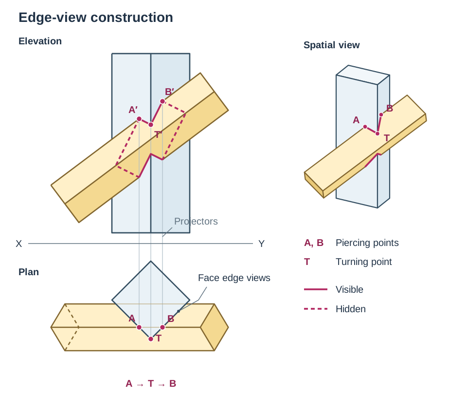
For solids with flat faces, all intersections are straight lines. You do not need arbitrary intermediate points. Instead, you find where the edges of one solid pierce the faces of the other by working in the view where those faces show as an edge view (a single line).
Step-by-Step Procedure
- Locate piercing points: In a view where a face appears as an edge (such as the plan of a vertical prism), mark where each longitudinal edge of the penetrating solid enters and exits the perimeter.
- Locate turning points: Check the vertical corner edges of the primary solid. If a corner edge falls within the width of the entering body, it cuts through that body's faces. These crossings are the turning points where the path bends.
- Project between views: Project all piercing and turning points onto their matching edges in the adjacent view (e.g. from plan up to elevation).
- Join in sequence: Connect points face by face in rotational order around the perimeter with ruled straight lines. The path must bend at every turning point located on a fold edge.
- Determine visibility: A line of interpenetration is visible only if it lies on a visible surface of both solids in that view. Obscured segments must be drawn as dashed lines. Trim the edges of each solid at their piercing points so no solid edge passes uninterrupted through the interior of the other.
Curved Surfaces: Generators, Cutting Planes, and Spheres
Curved surfaces lack planar corners. You resolve them by slicing the solids into simple 2D shapes.
The Generator Method (Cylinders)
A cylinder's surface consists of parallel straight lines called generators:
- Divide the circle into twelve equal 30° divisions and number them 1 to 12. Include extreme silhouette points.
- Draw these generators across the other orthographic views.
- Where a generator strikes the surface or edge view of the mating solid, mark the penetration point and project it to the corresponding generator line in the companion view.
Horizontal Cutting Planes
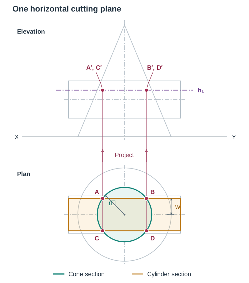
A level plane sliced through both solids at height produces simple geometric sections:
- A right cone gives a concentric circle of radius , where is base radius and is total height.
- A sphere of radius sliced at distance from its centre gives a circle of radius .
- A vertical cylinder reproduces its circular base.
- A horizontal cylinder gives a straight rectangular strip of half-width , where is cylinder axis height.
Where the section outlines cross in plan gives the piercing points at height . Project them vertically to cutting plane line in elevation. Repeat for 4 to 6 levels.
Sphere Intersections
Horizontal cutting planes are the standard choice because every level plane cuts a sphere in a true circle in plan. Find where the sphere's circle and the other solid's section cross in plan, then project to elevation.
Special Case: When the axis of an intersecting cylinder passes directly through the centre of a sphere, the intersection line is a true circle perpendicular to that axis. In the view where the cylinder axis is parallel to the plane of projection, the intersection appears as a straight line.
The Radial Elements Method and Line Piercing
When a cone or pyramid is penetrated, cutting planes passed through the apex cut straight surface lines rather than curved conic sections.
Radial Elements on Cones and Pyramids
- Locate the apex in plan and elevation. For a truncated cone or pyramid, extend the sloping sides to recover the original apex before drawing elements.
- In the view showing the end profile of the penetrating body, draw straight lines from through each corner or edge, extending them to the base line.
- Project the base crossing points to the adjacent view and connect them back to , establishing the matching element on the surface.
- Find where each penetrating edge intersects its specific radial element. Project these piercing points to the companion view.
- Draw a smooth curve through the points. Use a flexi-curve or French curve and keep the line even.
Where a Line Pierces a Curved Surface
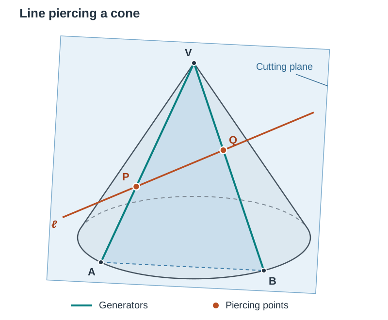
To find where an isolated line pierces a curved surface, place the line into a plane that cuts the solid along straight lines:
- Cone: Use the plane containing the line and the apex. It cuts the base circle at two points; draw the two generators to the apex. The points where the line crosses those generators are the piercing points.
- Cylinder: Use the plane containing the line and parallel to the cylinder axis. It cuts the cylinder along two straight generators that cross the line at the piercing points.
- Sphere: Use a vertical plane containing the line. The plane cuts the sphere in a circle of radius , where is the perpendicular distance from the sphere centre to the plane. Rebate that circle, mark the crossings with the line, and project back.
Auxiliary Views, True Shapes, and Dihedral Angles
Auxiliary Views: The Transfer Rule
An auxiliary elevation is projected from the plan looking in a new direction. All heights come from the existing elevation:
- Project every corner of both solids from the plan perpendicular to the new ground line .
- For each corner, measure its height above in the given elevation and step that height from along its projector.
- Complete the outline and transfer interpenetration points using the same heights.
For an auxiliary plan, project from the elevation perpendicular to , and transfer distances measured from in plan. Memory hook: project from the view next to the new ground line, measure from the other view.
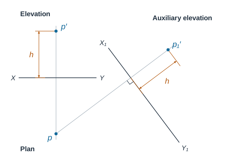
Finding the True Shape of a Surface
A sloping face appears foreshortened in standard views. To find its true shape:
- Find the view where the surface appears as an edge view (a single straight line).
- Draw parallel to that edge view.
- Project every vertex from that edge view perpendicular to .
- Measure the distance of each vertex from the ground line in the other view, and step that distance from .
- Join the points in order and label the view "True shape of surface S".
Dihedral Angle (Higher and Ordinary Level)
The dihedral angle is the true angle between two plane surfaces, measured perpendicular to their common edge:
- Obtain a view showing the common edge in true length (use an auxiliary view with parallel to the edge if needed).
- Draw a second ground line perpendicular to that true-length edge.
- Project both surfaces into this new view. The common edge collapses to a point, and each surface collapses to an edge view.
- Measure the angle between the two straight lines at that point with a protractor.
Surface Developments, Hole Openings, and Triangulation
A development is the complete unfolding of a solid's surface onto a flat plane.
Parallel-Line Development (Cylinders and Prisms)
The stretch-out line equals the perimeter for a right prism, or the calculated circumference for a right cylinder:
Calculate this value directly. Dividing the calculated circumference avoids cumulative chord errors from divider stepping. Erect perpendicular generators at equal intervals and step off true generator lengths.
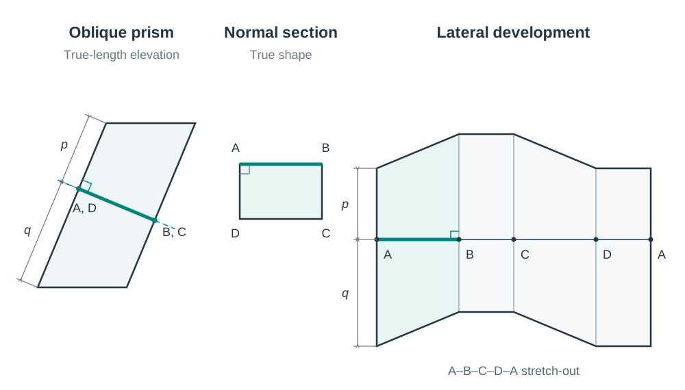
For an oblique prism or cylinder, cut a normal section perpendicular to the parallel edges or generators and obtain its true shape. Set the true distances between successive edges or generators off along a straight stretch-out line drawn at right angles to the generators. Then erect each generator's true length above and below that line, taking the lengths from the view in which the generators appear in true length, and join the ends. An oblique pyramid is developed by triangulating its faces from the true lengths of every corner edge on a single true-length diagram.
Developing the Opening (Hole) in the Main Pipe
- Lay out the main pipe's stretch-out line () and divide it into matching generator positions.
- In plan, measure the arc distance from the seam to each penetration point.
- Mark that distance along the stretch-out line and erect the corresponding height taken from the elevation.
- Connect the plotted points with a smooth curve. Because symmetrical branches produce symmetrical openings, construct one half and mirror it.
Radial-Line Development (Cones and Pyramids)
- Right cone: Develops as a sector of radius equal to the true slant height and included sector angle:
Project all intermediate curve points horizontally onto the extreme outer silhouette generator in elevation to read their true radial distance from the apex before swinging them onto the pattern.
- Right pyramid: Find the true length of one corner edge. Swing that radius from the apex, then step the true base edge length as a straight chord along the arc for each face. Join each chord to the apex. Never use the sector angle formula for a pyramid.
Triangulation for Transition Pieces (Option 4)
Used for transition pieces connecting different profiles (e.g. square-to-round ductwork):
- A square-to-round piece divides into four flat plane triangles (base side to a point on the circle) and four conical corner portions subdivided into smaller triangles.
- Build all edge true lengths on a single true-length diagram using a common vertical height line ().
- Lay out triangles side by side using compass arcs, starting from the seam and mirroring across the axis of symmetry.
Shortest Distance Measured Over a Surface
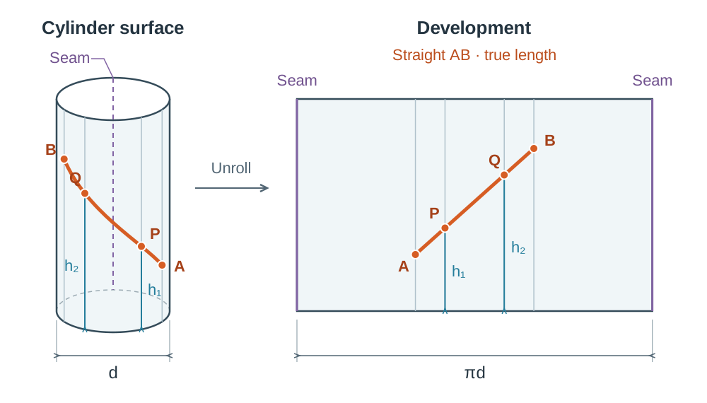
The shortest route between two points across a curved surface is not straight in plan or elevation. It is a straight line on the development, because the development represents the surface flattened without distortion.
- Develop the surface using parallel-line or radial-line development.
- Plot both points on the development:
- On a cone, project each point horizontally in elevation onto the outer outline generator to find its true distance from the apex, then mark that radius on the matching generator on the development.
- On a pyramid, draw a line from the apex through the point in plan and extend it to the base edge; find that line's true length by rotation or from a true-length diagram, mark the point along it in the same proportion as it divides the line in plan, and transfer that true distance to the matching face on the development.
- On a cylinder or prism, set off the point's generator position along the stretch-out line and step up its true height.
- Connect the two plotted points with a straight line. Measure this line to obtain the true length of the shortest path.
- To project the route back onto the solid, mark where the straight path crosses each generator on the development, transfer those heights back to the corresponding generators in elevation and plan, and connect them with a smooth curve.
Key terms
- Line of Interpenetration
- The common boundary line or space curve formed where the surfaces of two intersecting solid bodies meet.
- Piercing Point
- A discrete point where an edge or surface generator of one solid passes through a face or curved surface of another solid.
- Turning Point
- A point on an intersection line where the path changes direction across an edge, reaches an outline tangent, or transitions between visible and hidden detail.
- Edge View
- A projection in which a planar surface (or a cylinder viewed along its axis) appears as a single straight line.
- Generator
- A straight line lying on a surface, running parallel to the axis on a cylinder or connecting apex to base on a cone or pyramid.
- Cutting Plane
- An imaginary slicing plane passed through intersecting solids to produce simple cross-sections whose crossings locate intersection points.
- Normal Section
- A cross-section taken perpendicular to the parallel edges or generators of an oblique solid, whose true shape establishes the true stretch-out baseline.
- Development
- The complete unrolling or unfolding of a 3D solid's surface onto a flat 2D plane without stretching.
- Stretch-Out Line
- The baseline of a development whose length equals the full unfolded perimeter or circumference of the solid.
- True Length
- The actual unforeshortened measurement of a line, seen only when viewing perpendicular to that line.
- True Shape
- The actual unforeshortened outline of a planar surface, obtained by viewing perpendicular to its edge view.
- Dihedral Angle
- The true angle between two intersecting plane surfaces, measured in a view where their common line of intersection appears as a point.
- Triangulation
- A development method for transition pieces where curved or irregular surfaces are divided into adjoining triangles whose true lengths are plotted.
- Transition Piece
- A ductwork connector that transitions smoothly between ducts of different cross-sections, such as square-to-round.
- Frustum
- The portion of a cone or pyramid remaining after its top is removed by a cutting plane parallel to the base. If the cut is inclined, the solid is truncated.
Check yourself
What geometric shape is formed by the intersection of two plane polyhedra?
A closed series of connected straight-line segments that bend only at turning points located on corner edges.
A sloping surface appears as a 70 mm straight line in plan; its two ends are 15 mm and 55 mm above XY in elevation. How do you find its true shape?
Draw X1Y1 parallel to the 70 mm edge view in plan. Project every vertex perpendicular to X1Y1, and step off the heights 15 mm and 55 mm measured from XY in elevation.
A vertical cone of base radius 45 mm and height 90 mm is cut by a horizontal plane 30 mm above its base. What is the radius of the circular cut?
r = R (H - h) / H = 45 (90 - 30) / 90 = 45 * (60 / 90) = 30 mm.
What two views are required to determine the dihedral angle between two intersecting planes?
First, an auxiliary view showing their common line of intersection in true length. Second, an auxiliary view looking along that true-length line so it collapses to a point, showing both planes as edge views.
Why is the shortest route between two points on a curved surface drawn as a straight line on the development rather than on the plan or elevation?
The development represents the surface flattened out without stretching or distortion, so the shortest distance between two points is a straight line on the flat pattern.
Under the 2027 Leaving Certificate DCG exam arrangements, what is the structure of the written examination?
Section A (Core): answer 3 of 4 questions (20 marks each). Section B (Core): answer 2 of 3 questions (60 marks each). Section C (Options): answer 1 of 5 questions (60 marks). Total = 240 marks (60% of the subject).