

Timber is a versatile, renewable structural material, but because it is hygroscopic, it absorbs moisture from the air around it and releases it as conditions change. If damp is allowed to build up, wood will decay. In Irish domestic construction, keeping structural timber safe requires maintaining its moisture content below 20% through proper seasoning, careful detailing at junctions, and effective ventilation. Uncontrolled moisture leads to both surface and interstitial condensation, creating ideal conditions for destructive wood-rotting fungi like wet rot and dry rot. This topic connects building physics—humidity, dew point, psychrometric chart analysis, and ventilation rates—with practical construction detailing for suspended timber ground floors, open fireplace hearths, timber-frame walls, and cold versus warm roofs.
Timber Structure, Moisture Dynamics, and Seasoning
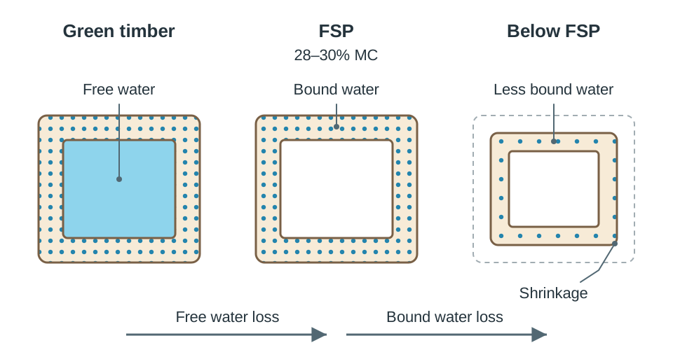
Wood is composed of elongated, hollow cellular fibres running along the trunk of the tree. When felled, timber holds moisture in two forms: free water held within open cell cavities, and bound water absorbed inside the cell walls.
As green timber dries, free water evaporates first. Once all the free water has left the cavities while the cell walls remain fully saturated, the wood reaches its fibre saturation point (FSP), which occurs between 28% and 30% moisture content. Shrinkage, distortion, and strength gains only begin below the FSP, because removing bound water draws the cell walls closer together.
Moisture content is measured on an oven-dry mass basis:
Timber eventually reaches an equilibrium moisture content (EMC), where its internal moisture balances the temperature and relative humidity of the surrounding air. Structural timber must be seasoned to match its working environment before it is closed in:
- External woodwork: 16% to 18% moisture content.
- Structural carcassing (roof rafters, floor joists, stud framing): 12% to 16% moisture content (maximum 18% prior to enclosure).
- Internal joinery, floorboards, and heated rooms: 8% to 12% moisture content.
Seasoning Methods
- Air seasoning: Timber is stacked on level concrete piers at least 300 mm above ground to prevent splash-back. Clean timber spacers called stickers (roughly 25 mm thick) separate each layer at 600 mm centres to allow cross-ventilation. Stacks have an overhanging roof to shed rain, and board ends are painted or waxed because water escapes fastest through the end grain. In Ireland, air seasoning cannot bring timber below roughly 17% to 20% moisture content.
- Kiln seasoning: Timber is stacked inside an insulated chamber where temperature, humidity, and airflow are mechanically controlled. Live steam is injected early on to keep the outer surfaces supple while core moisture moves outward; temperature is then raised and humidity lowered. Kilning takes days or weeks, achieves 8% to 12% moisture content, and sterilises the wood by killing insect pests and fungal spores.
Conversion and the Direction of Shrinkage
Timber shrinks very little along its length. It shrinks about twice as much tangentially (along the growth rings) as it does radially (across the rings). This unequal shrinkage causes distortion.
- Through-and-through (plain/slab) sawing cuts the log in parallel slices. It is fast, cheap, and produces little waste. However, boards away from the centre have growth rings curving across their width, so they shrink more on the bark face and cup away from the heart.
- Quarter sawing cuts logs so growth rings run roughly perpendicular to the board face. Shrinkage across the width is mainly radial, so the boards stay flat, wear evenly, and show attractive grain figure. It is slower and more wasteful, making quarter-sawn timber more expensive and reserved for joinery, stair treads, and flooring.
Lay plain-sawn floorboards heart side down (growth rings curving downwards). Because the board cups away from the heart, the edges will tend to lift rather than the middle humping up, so nailing near each edge holds the board flat.
Strength Grading, Board Materials, and Preservation
Softwoods from coniferous trees (such as spruce, Scots pine, and Douglas fir) provide the main structural carcassing for domestic buildings due to straight growth, rapid replenishment, and easy conversion. Hardwoods from broadleaf deciduous trees (such as oak, ash, and beech) are denser, slower growing, and more expensive, making them suitable for high-wear internal joinery like stairs, handrails, and flooring.
Appearance alone does not establish load-bearing capacity; timber must be stress graded:
- Visual grading: An inspector checks for knots, slope of grain, wane (bark on the edge), splits, and growth ring width.
- Machine stress grading: An automated machine bends each piece under a set mechanical load, measuring its modulus of elasticity (stiffness).
- Strength classes: Graded softwoods carry an EN 338 stamp. C16 is standard for general joists, stud partitions, and ceiling ties, while C24 provides higher bending and shear strength for longer spans and heavier loads.
Manufactured Boards in Wet and Structural Environments
- Plywood: Made of an odd number of wood veneers bonded with adhesive, with adjacent plies laid at 90° grain orientation. It offers uniform cross-grain strength and high dimensional stability for structural sheathing and flat roof decks.
- Oriented Strand Board (OSB): Made of compressed wood strands bonded with resin in perpendicular layers. OSB/3 is a moisture-resistant structural board widely used for timber-frame wall sheathing and sub-flooring.
- Particleboard (chipboard): Made from bonded wood chips. Moisture-resistant flooring grade (P5) is used for domestic floor decks, but unprotected cut edges swell permanently if exposed to persistent leaks.
- Medium Density Fibreboard (MDF): Made of broken-down wood fibres bonded under heat and pressure. It provides a smooth surface for painted skirtings and architraves, but standard MDF has poor moisture resistance and swells rapidly if damp.
Preserving Structural Timber
Preservatives protect timber against biological attack when moisture cannot be avoided:
- Water-borne copper salts: The standard industrial treatment for structural carcassing, soleplates, and roof timbers. The salts fix chemically in the wood cells, leaving a greenish tint, and can be painted over once dry.
- Organic-solvent preservatives: Carried in spirit, which allows deep penetration without swelling the wood; widely used for external joinery like window frames and doors.
- Tar oils (such as creosote): Inexpensive and durable for exterior fencing, utility poles, and railway sleepers, but unsuited to domestic buildings because they smell, stain, and bleed through paint.
Application methods range from surface painting to industrial processing:
- Brushing or spraying provides surface-level protection; used on site to re-treat cuts, notches, and drilled holes.
- Dipping or steeping timber in open tanks gives deeper penetration for factory joinery.
- Double vacuum (vac-vac) cycles extract air, flood timber with solvent, and pull a second vacuum to reclaim excess liquid.
- Vacuum-pressure impregnation forces chemical salts deep into the sapwood under high cylinder pressure. This is required for soleplates, wall plates, and roof timbers. Any cutting, notching, or drilling on site exposes untreated timber, so brush two liberal coats of preservative onto every cut surface before fixing.
Insect Attack
The common furniture beetle (woodworm) attacks softwoods and hardwoods. Adult beetles lay eggs in cracks and unsealed end grain. The larvae burrow through the wood for two to three years, causing structural weakness. Attacks show up as circular flight holes 1.5 mm to 2.0 mm wide, with fine powdery dust called frass underneath. To treat an active attack, improve ventilation, bring the timber moisture content down, cut out structurally weakened members, apply an insecticidal treatment by spray or pressure injection, and rebuild using pre-treated timber.
Fungal Decay: Wet Rot and Dry Rot
Fungi feed on the cellulose and lignin in wood, destroying its structural strength. Spores exist everywhere in the air, but they need four simultaneous conditions to grow: a timber food source, oxygen, suitable temperature (10 °C to 30 °C), and water. Keep the moisture content of timber below 20% and fungi cannot germinate. Surface moulds can grow on damp wall finishes at high relative humidity, but structural wood decay requires wet timber.
Dry Rot (Serpula lacrymans)
Despite its name, dry rot cannot start on dry timber; it requires an initial moisture content of 20% to 22%. Once established, it is destructive because it can spread across dry materials:
- Hyphae and rhizomorphs: The fungus develops root-like water-carrying strands called rhizomorphs. These travel through and across brickwork, mortar joints, and stone, transporting water from a damp spot to wet previously sound timber.
- Visual appearance: Infected timber shows deep, distinct cuboidal cracking across and along the grain, leaving the wood dry, brittle, and crumbly. In dark, damp conditions, white cotton-like mycelium forms with yellow or lilac patches. When mature, it produces a fleshy pancake-shaped fruiting body (sporophore) that scatters millions of rust-red spores as fine brown dust.
Wet Rot (Coniophora puteana)
Wet rot needs much higher, sustained moisture levels, typically 30% to 50%, caused by leaking pipes, defective gutters, or bridged damp proof courses:
- Confinement: Wet rot cannot travel across masonry and cannot transport moisture. Its decay stays strictly confined to the timber that is directly wet.
- Visual appearance: Wood darkens (brown rot) and develops thin longitudinal cracks along the grain, often covered with delicate, dark brown or black fern-like strands. The wood softens and collapses beneath the surface.
| Diagnostic Feature | Dry Rot (Serpula lacrymans) | Wet Rot (Coniophora puteana) |
|---|---|---|
| Moisture required to start | 20% to 22% moisture content | 30% to 50% moisture content (constant water source) |
| Spread through brickwork/masonry | Yes, conducts moisture via rhizomorph strands | No, strictly confined to wet timber |
| Timber decay pattern | Deep cuboidal cracking, brown and crumbly | Longitudinal cracking, dark/black, soft core |
| Fruiting body and spores | Fleshy plate with rusty red-brown spore dust | Thin sheet rarely seen indoors; olive-brown spores |
| Scent | Distinct musty mushroom odour | Damp, earthy cellar odour |
Wet rot stops once the water leak is cured and the timber dries out. In contrast, dry rot carries its own water supply through masonry into dry rooms, which is why repairing dry rot requires sterilising the surrounding masonry as well as cutting back the affected timber.
Remediation of Fungal Decay
Eradicating fungal attacks requires an ordered sequence of corrective measures:
- Eliminate the moisture source: Repair roof leaks, unblock gutters, rectify bridged DPCs, and restore sub-floor air vents. Deprived of water, fungi cannot continue metabolising wood.
- Expose the full outbreak: Lift floorboards, strip wet plaster, and follow the fungal hyphae and rhizomorph strands along joists and into wall cavities.
- Cut back decayed timber: Cut infected timber back well beyond the last visible sign of decay—at least 450 mm to 500 mm into clean, sound timber—because microscopic hyphae travel ahead of visible cracking. Remove and burn the cut timber off site to avoid spreading spores.
- Sterilise masonry: In dry rot attacks, strip plaster back 500 mm past the furthest trace of fungus. Rake out loose mortar joints, heat-sterilise the masonry face with a gas torch where safe, and apply or pressure-inject a deep-penetrating masonry biocide.
- Rebuild with treated timber: Replace removed joists and plates using timber that has undergone vacuum-pressure impregnation. Brush-apply two coats of preservative to every cut end or notch made on site.
- Isolate and ventilate: Bed all joist ends and wall plates on a damp proof course so that no timber touches masonry directly, or carry joists in galvanised steel joist hangers. Clear the sub-floor or roof void to re-establish continuous cross-ventilation.
Psychrometrics, Humidity, and Condensation Physics
Air holds water vapour, but its holding capacity depends on temperature. Warmer air holds significantly more water vapour than cold air.
- Dry-bulb temperature: The actual air temperature measured by a standard thermometer shielded from radiant heat.
- Wet-bulb temperature: The temperature measured by a thermometer whose bulb is covered by a damp wick in moving air. Evaporation cools the bulb. In drier air, water evaporates faster, lowering the wet-bulb reading. The gap between dry-bulb and wet-bulb temperatures is the wet-bulb depression; a larger depression indicates drier air.
- Saturated vapour pressure (SVP): The maximum pressure water vapour can exert in air at a given temperature before the air is saturated.
- Relative humidity (RH): The percentage ratio of actual vapour pressure to the saturated vapour pressure at the same dry-bulb temperature:
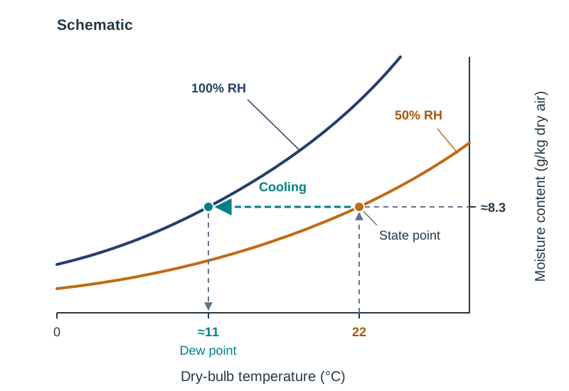
- Dew point: The temperature to which air must be cooled at constant moisture content to reach 100% relative humidity. When air touches a surface colder than its dew point, water vapour condenses into liquid water.
Saturated Vapour Pressure Reference Values
| Temperature (°C) | 0 | 5 | 6 | 8 | 10 | 12 | 14 | 16 | 18 | 20 | 22 |
|---|---|---|---|---|---|---|---|---|---|---|---|
| SVP (kPa) | 0.61 | 0.87 | 0.94 | 1.07 | 1.23 | 1.40 | 1.60 | 1.82 | 2.06 | 2.34 | 2.64 |
Reading a Psychrometric Chart
- Find dry-bulb temperature along the horizontal bottom axis and trace vertically upward.
- Locate the intersection with the curved relative humidity line (or the diagonal wet-bulb line) to pinpoint the state point.
- From that state point, read straight across to the right-hand vertical axis to find the moisture content in grams of moisture per kilogram of dry air ().
- Travel horizontally left from the state point to the 100% saturation curve, then look straight down to the temperature axis: that reading is the dew point.
For example, take air at 22 °C and 50% relative humidity. Read up from 22 °C to the 50% curve, then across to the right-hand axis to find a moisture content of roughly 8.3 g/kg. Moving horizontally left to the saturation line and dropping down gives a dew point of about 11 °C. Any cold surface in that room below 11 °C will run with water.
The Four Ways to Prevent Condensation
- Reduce moisture production at source: Use saucepan lids, dry clothes outdoors or in vented dryers, and run extract fans over hobs and showers.
- Increase ventilation: Provide background ventilation plus rapid mechanical extract in wet rooms (or an MVHR unit) to purge humid air before moisture accumulates.
- Raise internal surface temperatures: Add insulation, maintain insulation continuity at corners to eliminate thermal bridges, fit double or triple glazing, and run background space heating.
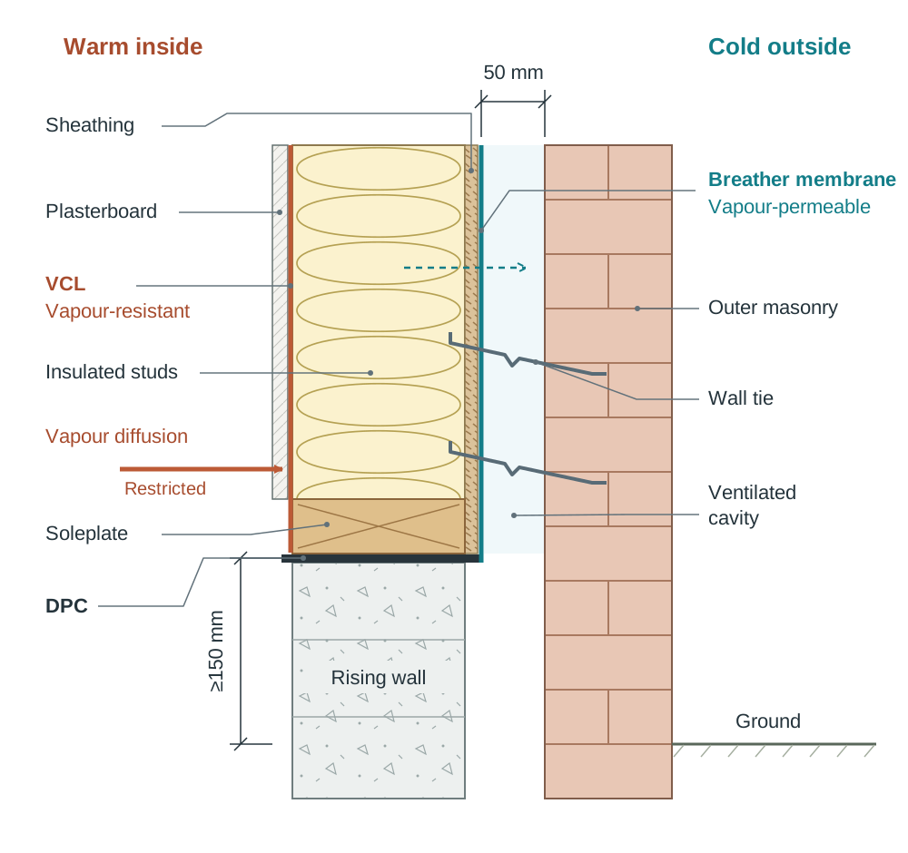
- Control vapour movement into building elements: Fit an airtight, sealed vapour control layer (VCL) on the warm room side of the insulation, and use a vapour-permeable breather membrane on the cold external side so moisture can escape outwards.
Moisture Barriers and Timber-Frame Wall Detailing
Condensation inside buildings happens in two ways:
- Surface condensation forms on exposed indoor surfaces (cold lintels, uninsulated corners, single glazing) when room air hits a surface colder than its dew point. This promotes black spot mould growth once surface relative humidity stays high.
- Interstitial condensation forms hidden inside wall, roof, or floor assemblies. Warm, moist air diffuses through plasterboard into the structure. As it hits cold outer layers, it drops below its dew point, dropping liquid water directly into the insulation and timber studs.
The rule to learn is: airtight and vapour-resistant on the warm side, vapour-permeable and weathertight on the cold side.
Timber-Frame Wall Layer Sequence (Inside to Outside)
- Internal finish: 12.5 mm plasterboard, skimmed or taped.
- Vapour control layer (VCL): 500 to 1000 gauge polythene sheet on the warm side of the insulation, with all laps and cable penetrations sealed with airtight tape.
- Timber stud frame: 140 mm × 44 mm structural softwoods (C16 or C24) fully packed between studs with mineral wool or rigid insulation.
- Sheathing board: 9 mm to 12 mm OSB/3 or plywood nailed to the exterior face of the studs to provide racking resistance against wind loads.
- Breather membrane: Water-repellent, vapour-permeable membrane fixed over the sheathing on the cold side. It keeps wind-driven rain out while letting trapped vapour escape.
- Ventilated cavity: Clear 50 mm air gap fitted with stainless steel wall ties sloping down toward the outer leaf to prevent water tracking across.
- Outer protective leaf: 102.5 mm brick or concrete blockwork with open weep periscope vents at the base.
In Question 1 drawings, show this build-up as a horizontal or vertical section at 1:5 or 1:10. Clearly annotate each layer, show the 50 mm cavity dimension, draw the wall ties falling toward the masonry, show the soleplate sitting on an internal rising wall at least 150 mm above finished ground level bedded on a continuous damp proof course, and add an arrow marked 'vapour diffusion' pointing from the room outward toward the cavity.
Suspended Timber Ground Floors and Hearth Details
A suspended timber ground floor isolates living areas from ground cold, but structural joists span over damp earth. Keeping the joists below 20% moisture content requires sub-floor cross-ventilation.
Sub-Floor Detailing (Building Regulations TGD Part C)
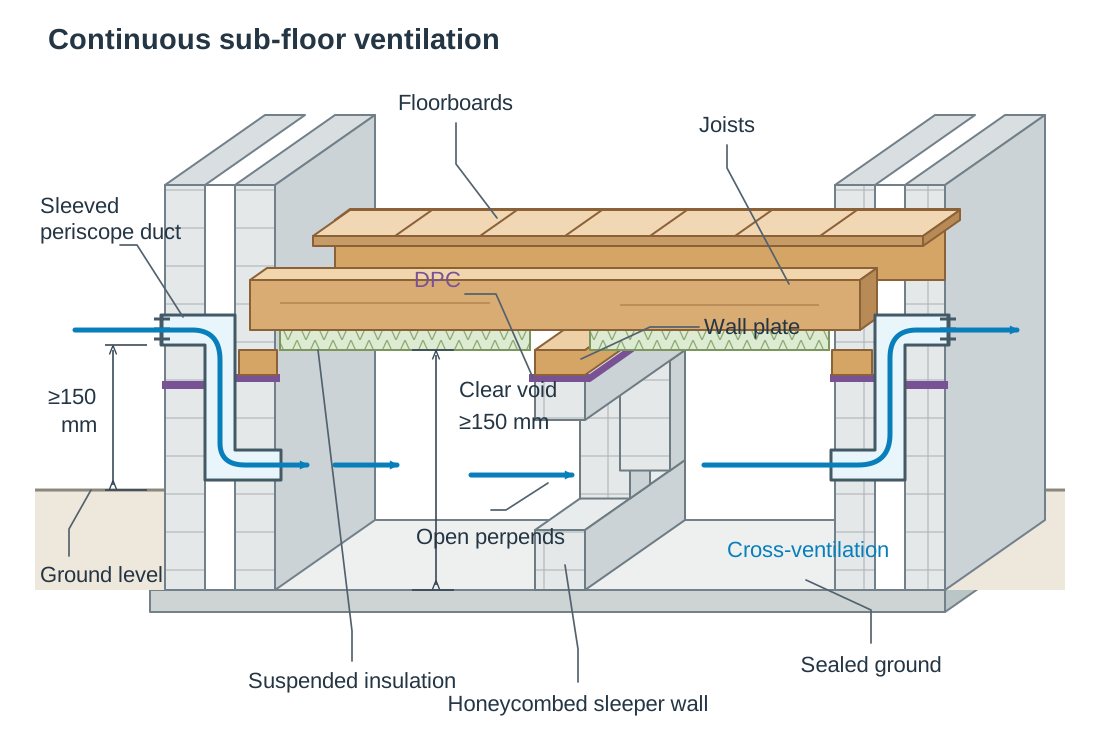
Under the Building Regulations (TGD Part C, Site Preparation and Resistance to Moisture), the void under a suspended timber floor must have openings on opposite sides giving at least 1,500 mm² per metre run of external wall, or 500 mm² per m² of floor area, whichever gives the larger area. (Always check current TGD figures for your exam year.)
- Ground sealing: Strip vegetable topsoil and lay 100 mm compacted hardcore blinded with sand, covered by a 1200 gauge DPM or 100 mm concrete oversite slab to stop moisture evaporating from the subsoil.
- Clear void: Maintain an unobstructed air space of at least 150 mm between the underside of joists (including any suspended insulation) and the oversite slab.
- Honeycombed sleeper walls: Build dwarf sleeper walls supporting intermediate joists with open vertical perpends (a honeycomb pattern) so cross-ventilation moves freely throughout the void without dead air pockets.
- DPC isolation: Bed every wall plate and joist bearing on a damp proof course so no timber touches masonry directly, or carry joists in galvanised steel hangers.
- Air vents: Connect external louvred air vents through the wall using telescopic (periscope) vent ducts, sleeved across the cavity so damp void air cannot enter the wall cavity. External vent grilles should sit at least 150 mm above finished ground level (and above the external DPC) so they cannot be blocked by soil, gravel, or surface splash.
Ground Floor Open Fireplace Hearth Junction
Where a timber floor meets an open fireplace and chimney breast, structural wood must be protected from heat:
- Constructional hearth: A solid concrete slab at least 125 mm thick, projecting at least 500 mm in front of the fireplace opening and at least 150 mm beyond each side. It is supported off foundation sleeper walls or the chimney breast, never off the timber floor.
- Timber clearance below hearth: Combustible materials beneath the hearth must be separated by an air space of at least 50 mm, or sit at least 250 mm below the top surface of the hearth.
- Clearance to flues: No combustible material may be placed within 200 mm of the inside face of the flue, or nearer than 40 mm to the outside face of the masonry chimney.
- Floor trimming: Joists running toward the fireplace are cut short and carried by a trimmer joist. The trimmer is supported by thicker trimming joists on either side, which are typically 25 mm thicker than common joists. Trimming members are hung using galvanised steel joist hangers.
- Permanent air supply: An open fireplace requires a permanent, non-closable air vent (commonly sized around 550 mm² free area per kW of appliance output above 5 kW under TGD Part J) to provide combustion air and stop smoke spilling into the room.
Roof Ventilation: Cold Pitched, Rafter-Level, and Flat Roofs
Warm, moist air leaking into roof spaces condenses against cold roofing membranes, felt underlays, and structural timbers unless the roof space is ventilated.
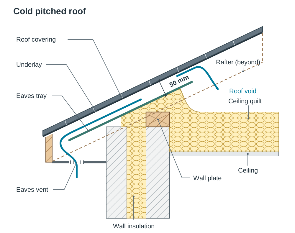
Process: Detailing a Cold Pitched Roof for Ventilation
- Fit a fascia vent and soffit strip giving the equivalent of a continuous 10 mm slot along both eaves—reason: creates a low-level inlet for cross-ventilation.
- Fix rigid eaves trays (rafter baffles) between the rafters at the wall plate—reason: prevents quilt insulation from expanding against the roofing felt and choking the air path.
- Maintain a 50 mm clear air gap between the top of the insulation and the underside of the sarking felt—reason: provides a guaranteed passage for air moving up the slope.
- Extend ceiling quilt insulation over the wall plate to meet the external wall insulation—reason: stops thermal bridging at the wall head without closing the 50 mm air path.
- Where the pitch exceeds 35° or the roof span exceeds 10 m, install ridge vents or tile ventilators giving the equivalent of a continuous 5 mm slot—reason: provides a high-level outlet so natural warm-air stack effect draws air through the roof.
- Seal the ceiling plane using taped plasterboard, sealed downlight hoods, and a draught-stripped attic hatch—reason: stops warm humid room air entering the roof void in the first place.
Pitched Roof with Insulation at Rafter Level (Attic Conversion)
When an attic is converted into living space, insulation moves up to the rafters, turning the roof slope into part of the heated envelope:
- Ventilated rafter construction (used with non-breathable felt): Fit insulation between and below rafters, maintaining a 50 mm clear ventilated air space between the top of the insulation and the underlay. This void must be ventilated at the eaves and ridge. A sealed vapour control layer sits directly behind the internal plasterboard on the warm side.
- Fully filled construction (used with a vapour-permeable breathable underlay): The full depth of the rafters is filled with insulation, with continuous insulated plasterboard added beneath the rafters to cut the thermal bridge through the wood. No 50 mm ventilation void is needed, because water vapour diffuses safely through the breathable underlay into the batten space below the slates. This requires a continuous, sealed airtightness/VCL membrane behind the plasterboard.
Getting Water off a Flat Roof: Falls and Firrings
A flat roof must never be dead flat. To prevent standing water, a design fall of at least 1:40 is specified to ensure a finished fall of at least 1:60 after structural deflection and timber tolerances. Standing water ponds on the roof, freezes and thaws, degrades the covering, and eventually finds joints to rot the deck.
The fall is formed using firring pieces: tapered timber strips fixed along the tops of the joists. The minimum firring depth is usually 25 mm at the low drainage end.
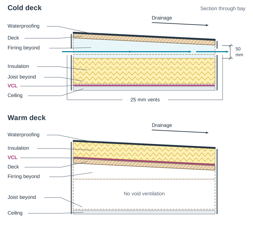
Flat Roof Types: Cold Deck vs Warm Deck
- Cold deck flat roof: Insulation sits between the timber joists below the roof deck. A continuous 50 mm clear ventilated air space must be kept between the insulation and the underside of the deck, ventilated at opposite ends with openings equal to a continuous 25 mm slot. A sealed VCL is installed on the warm room side. Cold decks are difficult to detail reliably in damp climates.
- Warm deck flat roof: Rigid insulation is fixed entirely above the structural timber deck, beneath the waterproof membrane. A high-performance VCL is bonded on top of the deck, under the insulation. Because the timber deck and joists sit on the warm side of the insulation, no void ventilation is needed. This removes condensation risk in the joists, provided the VCL is continuous and sealed at all edges, upstands, and pipe penetrations.
Domestic Ventilation, Airtightness, and Psychrometric Calculations
Daily household activities (cooking, washing, breathing) release between 7 and 14 litres of water vapour every day. An airtight envelope prevents uncontrolled draughts and fabric heat loss, but it requires planned, balanced ventilation to purge moisture.
Domestic Ventilation Provisions (Irish TGD Part F)
Under Building Regulations TGD Part F, naturally ventilated homes require three forms of ventilation (check the specific figures for your examination year):
- Background ventilation: Controllable permanent wall vents or window trickle vents providing roughly 6,500 mm² free area per habitable room.
- Purge ventilation: Openable windows or external doors with an openable area of at least 1/20 (5%) of the room floor area, allowing rapid clearance of fumes, steam, and heat.
- Mechanical extract in wet rooms: Sized at roughly 30 l/s for kitchens (or 60 l/s if not directly over the hob), 30 l/s for utility rooms, 15 l/s for bathrooms, and 6 l/s for separate WCs.
Mechanical Ventilation with Heat Recovery (MVHR) extracts warm, moist air from wet rooms through a central heat exchanger, warming incoming fresh outdoor air before supplying it to living rooms and bedrooms. Heat recovery efficiencies can exceed 90%, maintaining relative humidity in the healthy 40% to 60% range.
Sizing Airtightness
- The blower door test measures air leakage through the external envelope by sealing an adjustable frame and fan into an external doorway, pressurising and depressurising the house to a 50 Pa pressure difference.
- Airtightness is expressed as air permeability () in of envelope area at 50 Pa, or as air changes per hour (ACH50). Current Building Regulations TGD Part L set a backstop permeability of 5 at 50 Pa for new dwellings, while passive standards require approximately 0.6 ACH50.
- Smoke pencils and thermal-imaging cameras pinpoint leaks during testing—typically at service penetrations, floor-to-wall junctions, attic access hatches, and around window frames.
Trade-offs of Varying Ventilation Rates
Choosing a ventilation rate is always a trade-off between removing moisture and losing heat:
- High ventilation rate: Removes moisture quickly, pulling room relative humidity down and protecting cold surfaces and timber from rot. However, pulling in more cold outside air raises heating fuel consumption and carbon emissions.
- Low ventilation rate: Reduces heating energy loss, but allows moisture to accumulate. Indoor relative humidity rises above 70%, lifting the dew point and causing heavy condensation and black spot mould on cold thermal bridges.
Key terms
- Fibre Saturation Point (FSP)
- The point during timber drying (between 28% and 30% moisture content) where all free water has evaporated from the cell cavities while the cell walls remain saturated with bound water.
- Equilibrium Moisture Content (EMC)
- The condition where timber neither gains nor loses moisture, having balanced with the temperature and relative humidity of its surrounding environment.
- Dry Rot (Serpula lacrymans)
- A wood-decaying fungus that starts at 20% to 22% moisture content and conducts water through dry masonry via rhizomorph strands to feed on sound timber, producing cuboidal cracking.
- Wet Rot (Coniophora puteana)
- Wood-decaying fungi requiring sustained moisture contents between 30% and 50%, remaining strictly confined to timber exposed to a constant water source.
- Vapour Control Layer (VCL)
- An airtight, vapour-resistant membrane fitted on the warm room side of insulation to stop humid indoor air diffusing into cold structural timbers.
- Breather Membrane
- A weather-resistant, vapour-permeable membrane fitted on the cold outer side of sheathing to shed driving rain while letting internal vapour escape into a ventilated cavity.
- Honeycombed Sleeper Wall
- A dwarf brick or block wall supporting ground-floor joists, built with open vertical perpends to allow cross-ventilation to travel freely through the sub-floor void.
- Cold Deck Flat Roof
- A flat roof where insulation sits between joists below the deck, requiring a 50 mm clear ventilated airspace and continuous 25 mm eaves vents to clear moisture.
- Warm Deck Flat Roof
- A flat roof where insulation is fixed above the structural deck over a bonded VCL, keeping the timber structure warm and removing the need for void ventilation.
- Firrings
- Tapered timber battens fixed to the top of flat roof joists to create the fall (minimum 1:40 design fall) needed to drain rainwater.
- Trimmer Joist
- A transverse structural joist that carries the ends of cut common joists around an opening (such as a hearth or stairwell), transferring loads to trimming joists.
- MVHR
- Mechanical Ventilation with Heat Recovery: a system that extracts warm, stale air from wet rooms to pre-heat incoming fresh outdoor air via a heat exchanger.
Check yourself
What is the critical timber moisture content threshold below which fungal decay cannot occur?
20% moisture content. Keeping timber below 20% prevents spores from germinating and stops fungal decay.
How far into clean sound wood must joists be cut back when repairing dry rot?
At least 450 mm to 500 mm into sound, uninfected wood beyond the furthest visible trace of fungal hyphae.
What clearance must be kept between combustible timber joists and the inside face of a fireplace flue?
A minimum clearance of 200 mm from the inside face of the flue, and at least 40 mm from the outside face of the masonry chimney.
A room of 30 m³ is ventilated at 2 air changes per hour. Inside air is 20 °C / 60% RH (8.8 g/kg) and outside air is 4 °C / 90% RH (4.4 g/kg). With air density at 1.2 kg/m³, how much moisture is removed per hour?
Volume = 30 × 2 = 60 m³/h. Mass of air = 60 × 1.2 = 72 kg/h. Moisture difference = 8.8 - 4.4 = 4.4 g/kg. Moisture removed = 72 × 4.4 = 316.8 g/h ≈ 0.32 kg/h.
A flat roof spans 4.0 m with a design fall of 1:40 and a minimum firring depth of 25 mm. What depth of firring is required at the high end?
Rise = 4000 ÷ 40 = 100 mm. Depth at high end = 25 + 100 = 125 mm.
What minimum clear ventilation void must be maintained between insulation and roof underlay in cold pitched and cold flat roofs?
A continuous clear air path of at least 50 mm.