

Drainage in domestic construction safely carries surface runoff and foul wastewater away from a dwelling to prevent dampness, ill health, and pollution. At Leaving Certificate Higher Level, you must understand separate and combined systems, above-ground single-stack pipework, below-ground drain laying for both flexible and rigid pipes, substructure penetrations, testing procedures, and rural on-site wastewater treatment including site assessment, septic tanks, and percolation areas.
Principles of Drainage: Separate and Combined Systems
Every building produces two distinct categories of liquid waste. Surface water is clean rainwater collected from roofs, paved paths, and driveways. Foul water includes domestic greywater from sinks, baths, and washing machines, along with soil water (blackwater) from toilets and urinals.
The Separate System
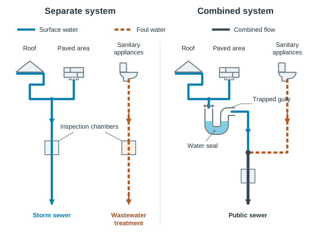
In a separate system, surface water and foul water flow through two completely independent pipe networks. Each system has its own inspection chambers and discharges to its own destination: surface water flows to a public storm sewer, stream, or soakaway, while foul water discharges to a municipal treatment plant or private septic tank.
- Advantages: The wastewater treatment plant only treats foul sewage, so it requires smaller tanks and lower operating costs. Heavy downpours cannot flood the treatment works or cause raw sewage to spill into rivers. In addition, rainwater downpipes can connect directly to surface water drains without needing water traps.
- Disadvantages: Installing two parallel sets of pipes and chambers costs significantly more in labour and materials. There is also a risk of misconnection, where a domestic foul waste pipe is mistakenly plumbed into a surface water drain, polluting local waterways.
The Combined System
In a combined system, surface runoff and foul sewage mix together in a single underground pipe running to a common public sewer.
- Advantages: It is cheaper and quicker to install because only one pipe run, one trench, and one set of chambers are required. Strong rainwater surges also help to flush accumulated solids through the pipework.
- Disadvantages: Municipal treatment plants must process enormous volumes of diluted wastewater during wet weather. In severe storms, combined sewer overflows can discharge diluted raw sewage directly into rivers. Crucially, every rainwater downpipe and yard gully must connect through a trapped gully, otherwise foul sewer gases will escape into the air right beside the house.
Fixing Gutters, Downpipes, and Surface Water Disposal
Eaves gutters collect runoff along the roof edge and channel it toward downpipes. Modern domestic guttering is usually half-round or square-profile uPVC. Tiles or slates should project roughly 50 mm into the gutter trough but must finish short of the centre line; if the roof overhangs past the centre line, fast-flowing stormwater will overshoot the gutter rim during heavy storms.
Fixing and Joining Gutters
- Fascia brackets support the gutter trough and are screwed to the fascia board at maximum 1.0 m intervals, with an extra bracket placed within 150 mm of every joint, corner, and outlet.
- Gutters are laid either dead level or with a slight fall of about 1:600 toward the outlet to prevent ponding and silt accumulation.
- Adjoining gutter lengths clip together inside union brackets fitted with compressible rubber gaskets, providing a watertight seal that still allows the plastic to expand and contract with seasonal temperature changes.
- External stop ends close off gutter runs, while a running outlet connects the channel to the downpipe.
Fixing Downpipes
- Rainwater downpipes drop vertically from the eaves. Under an overhanging roof, two offset bends form a swan-neck assembly that brings the pipe back tight to the finished external wall face.
- Downpipe clips secure the pipe to the masonry wall at maximum 1.8 m to 2.0 m centres, with a clip positioned directly beneath each pipe socket.
- Downpipe lengths are assembled with their factory sockets facing upward, so falling water cannot weep out through the joints.
- At ground level in a separate system, the downpipe enters a rest bend or back-inlet gully connected to the surface water drain. In a combined system, it must discharge over a trapped gully.
Soakaways and French Drains
Where no public storm sewer exists, clean runoff must disperse on site:
- A soakaway is an excavation located at least 5 m downslope from building foundations and boundaries. It is filled with clean broken stone (100 mm to 150 mm) or constructed from precast perforated concrete rings, wrapped entirely in a geotextile membrane to prevent surrounding soil from washing in and filling the stone voids.
- A French drain is a shallow trench containing a perforated land-drainage pipe bedded in clean pea gravel and lined with geotextile fabric. It intercepts sheet runoff along driveways and lawn perimeters before the ground becomes waterlogged.
Sanitary Fitments, Appliance Traps, and Trap-Seal Protection
Sanitary appliances must be durable, non-absorbent, and easy to keep clean. Vitreous china is standard for wash hand basins and water closets, acrylic or enamelled steel for baths, and stainless steel for kitchen sinks. When selecting and positioning fitments, allow enough activity space in front of each one for comfortable use. Also leave access space around and behind it for waste pipes, supply pipes, isolating valves, and future maintenance. Services are often boxed in behind removable panels.
Water Closets and Waste Connections
- Washdown WCs: The contents of the bowl are cleared by the direct impact and momentum of flushing water. They are simple, reliable, and economical, though slightly noisier.
- Siphonic WCs: The flushing water creates an internal siphonic pull that empties the bowl quickly and quietly with a larger retained water surface. However, they cost more and block more easily if bulky waste is introduced.
- A flexible, rubber-finned push-fit pan connector joins the WC spigot directly to the 100 mm soil branch pipe. Basins, baths, and sinks connect to their respective branch waste pipes through an appliance trap. Hot and cold supply pipes should always incorporate an isolating ball valve close to the appliance so maintenance does not require draining the whole house.
Appliance Traps and Water Seals
Every sanitary fitting must incorporate a trap holding a water seal to block foul gases and vermin. Sinks, baths, and basins require a minimum 75 mm depth of water seal, while WCs require a 50 mm seal. Common configurations include the P-trap (horizontal outlet through a wall), the S-trap (vertical outlet through a floor), and the compact bottle trap (commonly fitted beneath wall-hung basins).
Causes of Trap-Seal Failure
- Self-siphonage: When an appliance discharges and fills its branch pipe completely, the moving plug of water acts like a piston. It leaves a partial vacuum behind it that pulls the water seal out of its own trap right at the end of the discharge. This occurs if branch pipes are too long or laid at too steep a gradient.
- Induced siphonage: When a large volume of water flushes down the vertical stack from an upper appliance (such as an upstairs WC), the falling column drags air with it. This suction lowers the pressure inside lower branch pipes, pulling the water seals out of neighbouring basins, baths, or ground-floor showers.
- Back pressure: Near the bottom of the vertical stack, falling wastewater suddenly decelerates as it hits the horizontal drain. This deceleration compresses the air directly behind the base bend. If lower waste branches are connected too close to this turn, the compressed air blows wastewater and sewer smells violently back up through ground-floor trap seals.
Above-Ground Drainage: The Single-Stack System
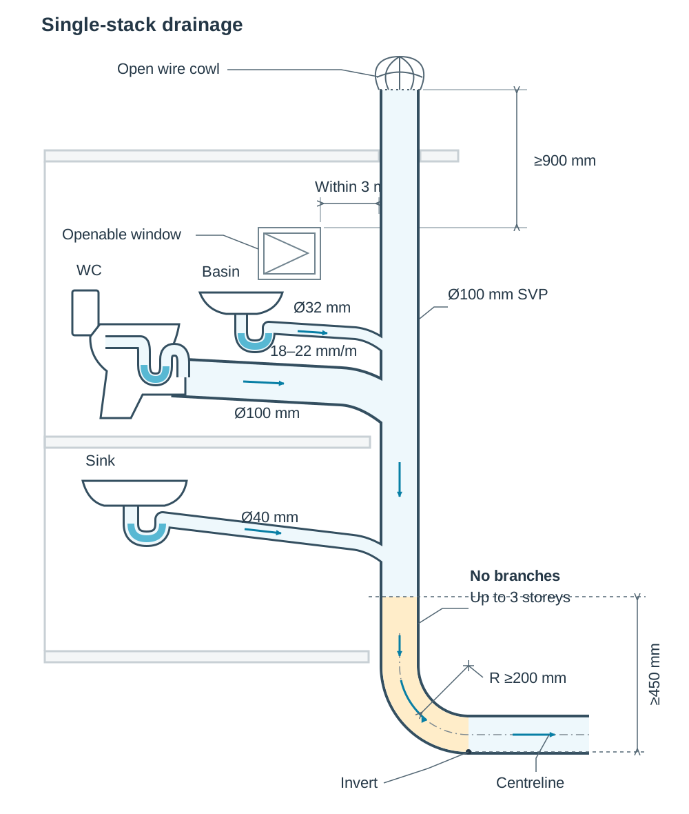
In a modern single-stack system, all soil appliances and wastewater fittings discharge into a single vertical 100 mm pipe known as the soil and vent pipe (SVP). This design does away with the old two-pipe arrangement that used external hoppers and open gullies.
To keep water flowing at a self-cleansing pace without tearing out trap seals, branch pipes must follow strict sizing, gradient, and length limits set out in Technical Guidance Document H (TGD H):
| Appliance | Pipe Diameter | Maximum Unvented Length | Permitted Gradient (Fall) |
|---|---|---|---|
| Wash Hand Basin | 32 mm | 1.7 m | 18 mm to 22 mm/m (approx. 1:50) |
| Kitchen Sink / Bath / Shower | 40 mm | 3.0 m | 18 mm to 90 mm/m (1:55 to 1:11) |
| Water Closet (WC) | 100 mm | 6.0 m | Min. 18 mm/m (approx. 1:50) |
| Main Vertical Stack | 100 mm | Through roof structure | Vertical |
Notice that the 32 mm wash-basin branch is restricted to a narrow gradient of 18 mm to 22 mm per metre. Because the basin waste is narrow, laying it at a steeper fall causes the pipe to run full-bore, triggering instant self-siphonage.
Stack Design Rules
- Ventilation: The 100 mm stack extends vertically through the roof and finishes with an open wire balloon cowl to vent gases safely. If the stack terminates within 3.0 m of an openable window or rooflight, the open top must finish at least 900 mm above the window head.
- Base Restriction Zone: In a dwelling up to three storeys high, no branch waste pipe may join the vertical stack within 450 mm of the invert level of the bend at the foot of the stack. This clearance keeps connections well away from the high-pressure zone created by falling water hitting the horizontal run.
- Base Bend Detailing: The transition from the vertical stack to the underground drain must be made using a large-radius bend (minimum radius 200 mm) or two 45° bends. A sharp 90° knuckle bend creates severe turbulence, splashing, and back pressure.
Minimising Blockages
To prevent blockages in the system, ensure: branches are sized correctly for each fixture; pipes maintain an even fall; branch connections join the main stack obliquely in the direction of flow rather than squarely; large-radius bends are fitted at all turns; and access eyes are installed at the head of every branch run for rodding.
Below-Ground Drainage: Laying Rigid and Flexible Drains
Underground drains carry foul wastewater away from the building by gravity. Domestic underground drainage pipes are typically made of terracotta-coloured uPVC (a flexible material) or vitrified clay (a rigid material). Cast iron or ductile iron is reserved for exposed situations, shallow crossings under heavy traffic, or suspended basement pipework.
Gradients and Self-Cleansing Velocity
Drains must achieve a self-cleansing velocity of 0.75 m/s to 1.0 m/s so suspended solids do not settle out. A 100 mm foul drain serving a WC should be no flatter than 1:80 (no flatter than 1:40 if there is no WC). Avoid falls steeper than about 1:20. Falls of 1:40 to 1:80 are typical in practice. A pipe laid flatter than 1:80 moves water too sluggishly, allowing solids to drop onto the pipe invert. Conversely, laying a pipe steeper than 1:20 causes the water to race ahead, leaving heavier solids stranded behind.
Laying Flexible Pipes (uPVC)
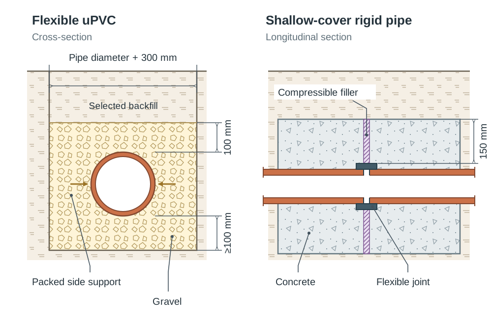
Flexible pipes bend slightly under ground loads and depend entirely on the surrounding granular fill for lateral side support. Excavate the trench to the pipe diameter plus 300 mm. Lay the pipe on a bed of at least 100 mm of 10 mm single-size gravel. After pushing spigot-and-socket ends together with lubricated rubber sealing rings, pack gravel evenly up the sides of the pipe barrel, and finish with a 100 mm layer of gravel over the pipe crown. The remaining trench is backfilled with selected soil free of large stones.
Laying Rigid Pipes (Vitrified Clay and Concrete)
Rigid pipes do not deform under load; they support earth and traffic weights through their own structural strength. On firm, uniform ground, vitrified clay pipes with factory push-fit flexible joints can be laid directly on a 100 mm granular bed, just like uPVC. Small recesses called hand holes must be scooped out of the gravel bed directly under each pipe socket, ensuring the barrel rests evenly along its entire length rather than rocking on its joints.
Where rigid pipes are laid with shallow cover (under 600 mm in gardens or under 1.2 m beneath driveways), the pipe must be bedded and haunched in concrete, or encased completely in a 150 mm concrete surround. To prevent ground movement from shearing the brittle pipe, compressible joint filler board (movement joints) must be cast into the concrete surround at every flexible pipe joint.
Passing Through Substructure Walls and Foundations
Where an underground drain passes through a rising wall or foundation trench, building settlement can easily crack the pipe. One of two construction details must be used:
- Lintel or Relieving Arch: Build a concrete lintel over the wall opening, leaving at least 50 mm clearance all around the pipe barrel. Mask the gap on both wall faces with rigid sheet material and pack it with a flexible, compressible sealant to keep out rodents, backfill, and water.
- Rocker Pipe: Build a short pipe piece into the wall with flexible joints located within 150 mm of each wall face. Directly outside, connect a short rocker pipe (maximum 600 mm long) on both sides. These short hinged segments allow the pipe to pivot smoothly if the building settles.
If a drain trench runs parallel to and deeper than an adjacent foundation, the trench must be filled with mass concrete up to the level of the foundation underside so the foundation does not lose its bearing support.
Access Chambers and Manholes
Underground lines must run straight between points of access. Provide access at the head of every run, at changes of direction or gradient, at junctions, and on straight runs at intervals not exceeding 45 m.
- Inspection Chambers: Used for depths up to 1.0 m to 1.2 m, allowing access from ground level for rodding equipment. Modern installations use 450 mm diameter uPVC chambers with pre-moulded channel bases.
- Manholes: Built when drain depth exceeds 1.2 m to permit physical human entry. Built from Class B engineering brick or precast concrete rings on a 150 mm concrete base slab, with minimum internal dimensions of 1200 mm by 750 mm.
- Benching: The floor on each side of the central half-round channel is formed with smooth concrete sloping upward toward the chamber walls. This benching directs splashing back into the channel and provides a safe, level footing for maintenance workers.
Pipeline Testing Procedures
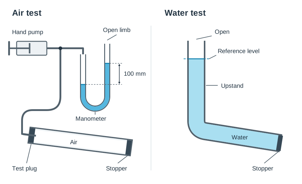
Before drainage trenches are backfilled with earth, every new drain run must be tested for watertightness to ensure wastewater cannot escape into the soil and groundwater cannot enter the system. Two standard tests are used.
The Air Test
- Insert an expandable rubber stopper into the lower end of the drain run and tighten the wing nut to compress the rubber ring firmly against the pipe walls.
- Insert a second test plug fitted with a hose nipple at the higher end of the pipe run.
- Connect a flexible rubber tube from the nipple to a hand pump and a U-tube water manometer.
- Pump air into the pipe until the manometer shows a pressure head of 100 mm of water.
- Leave the system undisturbed for 5 minutes. This settling period allows the compressed air to stabilise at the pipe's internal temperature.
- Observe the manometer over the following 5 minutes. The pressure must not drop by more than 25 mm of water. A larger drop indicates a leaking joint or cracked pipe.
The Water Test
- Insert an expanding rubber stopper into the lower end of the drain run.
- Fit a temporary vertical upstand pipe to the high end of the line.
- Fill the entire drain and upstand with clean water until a minimum pressure head of 1.2 m to 1.5 m of water is established at the upper end (taking care that the head at the lowest end does not exceed 4.0 m to protect lower seals).
- Let the filled pipe stand for 2 hours. This period allows vitrified clay pipes to absorb water and lets trapped air bubbles dislodge.
- Top the water in the upstand back up to the reference mark and observe it for 30 minutes. For a 100 mm diameter pipe, water loss must not exceed 0.05 litres per metre length of pipe run.
On-Site Wastewater Treatment: Site Assessment and Septic Tanks
In rural areas without public sewerage, domestic wastewater must be treated on site. Standard domestic effluent treatment involves two sequential stages: primary settlement inside a septic tank, followed by secondary biological purification through an aerated percolation area.
Site Assessment for Rural Dwellings
Before any on-site system is approved or built, the site must be surveyed following the EPA Code of Practice:
- Visual Assessment: Check the topography, slope, rock outcrops, surface vegetation (such as rushes indicating waterlogged ground), and the location of nearby streams, lakes, or wells.
- Trial Hole: Excavate a test hole at least 2.0 m deep and leave it open for 48 hours. Record the water table level and the depth to solid bedrock. The water table must sit well below the proposed drainage layer.
- Unsaturated Soil Depth: A septic tank system requires a minimum depth of 1.2 m of permeable, unsaturated subsoil beneath the base of the percolation trenches. This dry subsoil layer is where oxygen-breathing bacteria purify the passing effluent.
- Percolation Tests: Carry out the T-test to confirm the subsoil absorbs liquid at a safe, controlled rate.
Septic Tank Design and Operation
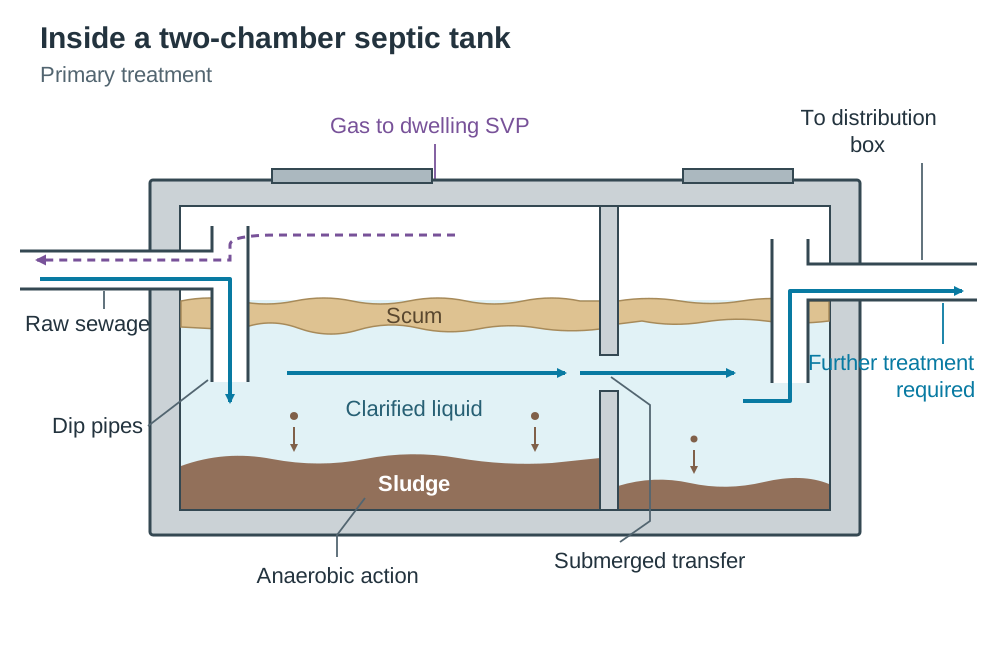
A septic tank is a watertight, two-chamber settlement vessel made of precast concrete or glass-reinforced plastic (GRP). The tank is sized according to the number of occupants it serves (population equivalent, PE), following EPA guidance. Structurally, the tank's overall length is roughly three times its width, and the first chamber is approximately twice the length of the second chamber.
Inside the tank, raw sewage undergoes primary treatment:
- Solid waste separates under gravity: heavy solids sink to the bottom as sludge, while oils, grease, and scum float to the surface.
- In the absence of free oxygen, anaerobic bacteria feed on the settled sludge, liquefying organic matter and reducing sludge volume.
- Gases generated during breakdown vent back through the inlet pipe and escape via the dwelling's roof-mounted soil vent stack.
- Submerged baffle walls or dip pipes at the inlet and outlet ensure that liquid is drawn only from the clarified middle layer, preventing floating scum or heavy sludge from washing downstream.
- Settled sludge must be desludged by an authorised contractor every 12 to 24 months to keep the tank working efficiently.
Separation Distances
Following EPA guidelines, the septic tank must be located at least 7 m from the dwelling and at least 3 m from site boundaries. To protect drinking water, the tank and percolation field must always sit downslope of private water wells, with separation distances determined from EPA site tables based on soil type and slope. The percolation area itself should be at least 10 m from the house and well away from surface watercourses.
Percolation Areas, Soil Testing, and Secondary Treatment
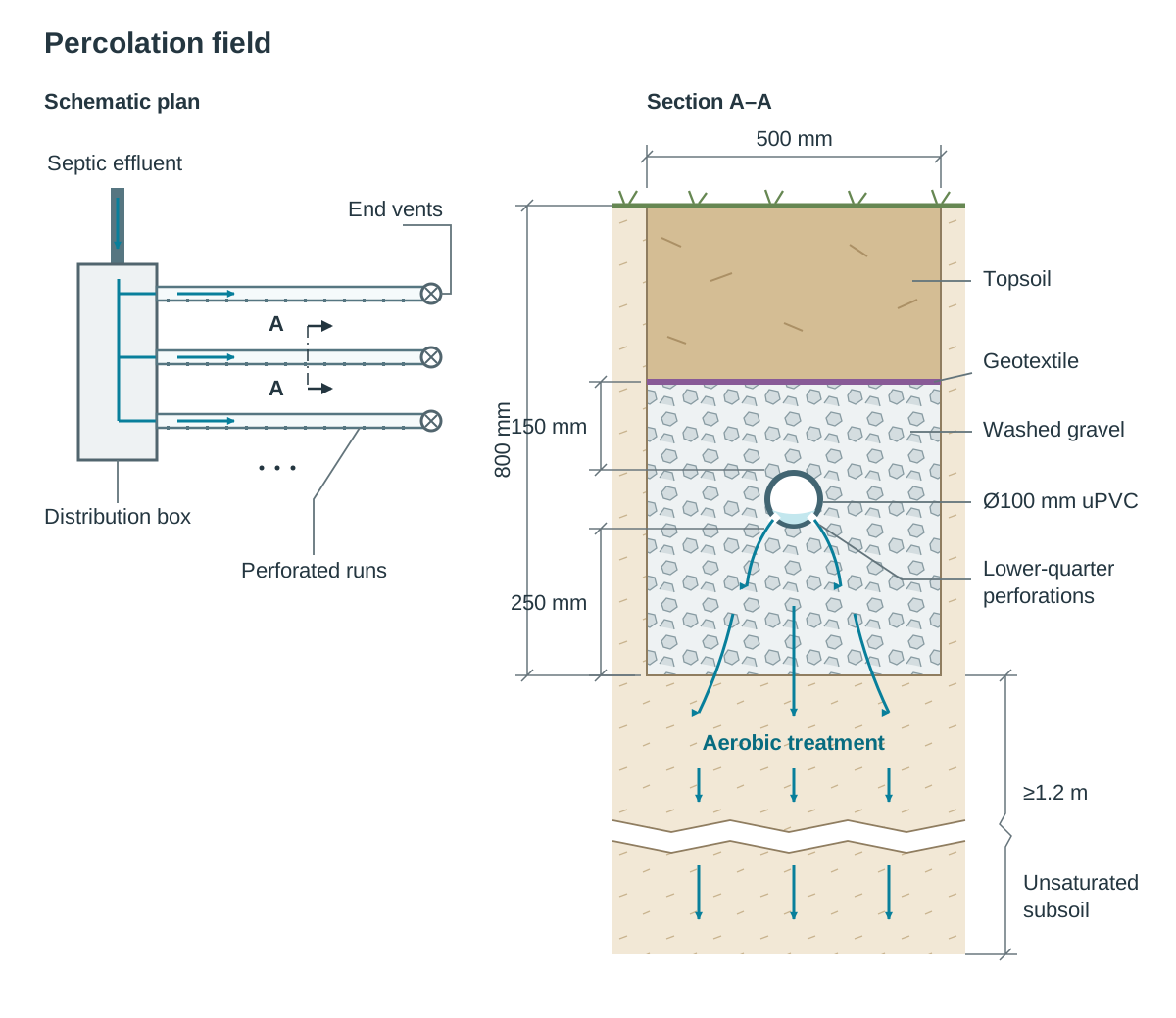
Liquid leaving the septic tank is still contaminated with pathogens and dissolved organic waste. It passes to a distribution box, which splits the flow evenly across an array of underground perforated pipes bedded in gravel trenches. Here, aerobic bacteria living in the oxygenated stone and subsoil complete secondary purification.
Percolation Trench Construction
- Trenches are excavated 500 mm wide and 800 mm deep.
- A 250 mm bed of clean, washed gravel aggregate (20 mm to 30 mm stone) is laid in the base.
- A 100 mm perforated uPVC pipe is laid along the gravel bed at a gradient of 1:200. The perforations face downward along the lower quarters to disperse effluent evenly.
- Clean gravel is placed around the pipe and brought up 150 mm over the pipe crown.
- A continuous layer of geotextile membrane is laid across the entire top of the gravel. This allows air and water vapour to pass freely, but stops backfilled soil from washing down and clogging the stone voids.
- The trench is covered with 150 mm to 300 mm of topsoil and grassed over, with a vertical vent pipe fitted at the end of each run to provide oxygen to the gravel bed.
The Percolation Test (T-Test)
The T-test measures the average time in minutes taken for water to fall 25 mm in a pre-soaked test hole dug into the subsoil.
- A very low T-value (below 3) means the soil is excessively loose or gravelly: wastewater drains through too quickly without adequate biological filtering, risking groundwater pollution.
- A very high T-value (above 50) means the subsoil contains dense, impermeable clay: effluent cannot soak away and will back up, ponding foul sewage on the ground surface.
Alternative Secondary Treatment Systems
Where site conditions are unsuitable for a standard septic tank and percolation field (due to poor soil percolation, high water tables, or shallow bedrock), a proprietary secondary treatment system is installed:
- Mechanical aeration units: Multi-chamber tanks that pump compressed air into the effluent, allowing aerobic bacteria to break down organic waste directly inside the tank.
- Intermittent sand or peat filters: Packaged filter beds where wastewater trickles through selected sand or peat media before discharging to a polishing filter.
- Constructed wetland reed beds: Shallow gravel basins planted with common reeds (Phragmites australis), whose roots supply oxygen and encourage microbial colonies that naturally cleanse wastewater.
Exam Answer Frames for Rural Wastewater
- Site Considerations (e.g. 2019 Q8): 1) Soil permeability confirmed by T-test. 2) Depth of water table and bedrock measured via a 2 m trial hole. 3) Site slope allowing gravity fall from the dwelling. 4) Recommended separation distances from buildings, boundaries, and wells. 5) Household occupancy setting the tank capacity. 6) Minimising odour and avoiding human contact with effluent.
- Functional Requirements (e.g. 2023 Q8): 1) Effective biological treatment separating solids and neutralising pathogens before discharge. 2) Watertight, durable construction resisting corrosion and stopping groundwater infiltration. 3) Correct tank capacity sized for the number of residents. 4) Safe maintenance access for desludging and rodding.
Key terms
- Surface Water
- Clean rainwater runoff collected from roofs, paved driveways, and footpaths that can be discharged into storm sewers, soakaways, or watercourses.
- Soil Water
- Blackwater discharge from toilets and urinals containing human waste that requires biological treatment.
- Greywater
- Domestic wastewater from baths, sinks, showers, and washing machines containing soaps and detergents but no toilet waste.
- Separate System
- A drainage layout where surface rainwater and foul sewage are conveyed in two completely independent pipe networks.
- Combined System
- A drainage network that carries both surface rainwater and foul sewage together in a single shared underground pipe.
- Trapped Gully
- A drainage fitting that holds a water seal to prevent foul sewer gas from escaping into the open air at surface entry points.
- Single-Stack System
- A domestic plumbing system where all above-ground waste and soil appliances discharge into a single vertical 100 mm soil and vent pipe.
- Water Seal
- A retained plug of water (typically 75 mm deep) maintained inside an appliance trap to prevent foul sewer air from entering living spaces.
- Self-Siphonage
- The loss of an appliance trap's water seal caused by negative pressure generated when that same appliance discharges full-bore.
- Induced Siphonage
- The loss of an appliance water seal caused by suction created when discharge from an upper fixture rushes down the vertical stack.
- Back Pressure
- Positive air pressure created when wastewater decelerates near the base of a vertical stack, blowing air back through lower trap seals.
- Invert Level
- The lowest internal point on the inside curved bottom of a drainage pipe or channel.
- Self-Cleansing Velocity
- A flow speed of 0.75 m/s to 1.0 m/s inside a drain pipe, which carries solids along in suspension without scouring the pipe surface.
- Hand Holes
- Recesses scooped out of a granular trench bed beneath pipe sockets so the pipe barrel rests evenly along its entire length.
- Benching
- Smooth, sloped concrete formed on each side of the channel in a manhole base to guide overflow back into the pipe and provide safe footing.
- Septic Tank
- A watertight, underground settlement chamber where heavy solids settle into sludge and undergo anaerobic digestion.
- Anaerobic Bacteria
- Microorganisms that thrive in the absence of free oxygen to break down and liquefy organic solids in the sludge layer of a septic tank.
- Aerobic Bacteria
- Oxygen-dependent microorganisms that feed on dissolved organic matter as effluent filters through aerated gravel and soil.
- Distribution Box
- A small chamber with level outlet weirs that splits septic tank effluent evenly across multiple percolation trench runs.
- Geotextile Membrane
- A permeable synthetic fabric laid over gravel in drainage trenches that allows air and moisture through while blocking fine soil silt.
- T-Test
- A standard percolation test measuring the average time in minutes for water to drop 25 mm in a pre-soaked test hole to determine soil absorption rates.
- Air Admittance Valve (AAV)
- A one-way mechanical valve that opens under negative pressure to admit air into a waste branch, protecting trap seals against siphonage.
Check yourself
Two inspection chambers are 18.0 m apart with invert levels of 100.600 m and 100.240 m. Find the gradient and state whether it suits a 100 mm drain serving a WC.
The vertical fall is 100.600 m - 100.240 m = 0.360 m. Gradient = length / fall = 18.0 / 0.360 = 50, giving a gradient of 1:50. This is within the acceptable range, so it is suitable.
Why is the gradient of a 32 mm unvented wash hand basin branch restricted to 18 mm to 22 mm per metre?
Because the small pipe diameter means a steeper slope causes the pipe to run full-bore, producing negative air pressure that pulls out the trap seal by self-siphonage.
How is the required capacity of a domestic septic tank determined in Ireland?
It is sized based on the population equivalent (PE) of the dwelling (the number of occupants it can accommodate) according to the EPA Code of Practice.
What is the purpose of hand holes excavated in the trench bed when laying rigid clay pipes?
They provide clearance beneath each pipe socket so the full length of the pipe barrel rests evenly on the granular bed rather than rocking on its joints.
In a drainage air test, what is the maximum permissible pressure drop over a 5-minute period after stabilisation?
A maximum drop of 25 mm of water from an initial test head of 100 mm on the manometer.