

Floors provide safe, load-bearing surfaces for occupants, furnishings, and interior partitions while acting as an essential barrier against ground moisture, soil gases like radon, heat loss, and sound transmission. In Leaving Certificate Construction Studies Higher Level, the study of floors requires a detailed understanding of solid concrete and suspended timber ground floor build-ups, upper floor timber framing, joist trimming around openings, sound insulation, domestic floor coverings, and compliance with the relevant Building Regulations.
Functions and Comparison of Ground Floor Types
A ground floor must satisfy six primary functions:
- Support loads: carry dead loads (self-weight of floor and partitions) and imposed loads (occupants and furniture) without excessive deflection.
- Resist ground moisture: prevent rising damp through capillary action.
- Prevent soil gas ingress: form an airtight, gas-resistant barrier against radon and other subsoil gases.
- Thermal insulation: limit heat loss to the ground to meet Building Regulations (TGD L).
- Durability and wear: provide a stable, level, and long-lasting walking surface.
- Fire resistance: restrict the spread of fire where required.
Comparing Solid Concrete and Suspended Timber Ground Floors
Solid Concrete Ground Floor
- Advantages: highly durable with zero risk of timber rot; excellent thermal mass to absorb and slowly release heat; ideal substrate for underfloor heating; provides a continuous ground gas barrier with no cold ventilated crawl space; silent underfoot without squeaks.
- Disadvantages: slow drying-out period for the concrete slab and wet screed; impractical and expensive on sloping sites where hardcore fill exceeds 900 mm; services buried under or within the slab are difficult to access or modify later; feels hard and cold underfoot if unheated.
Suspended Timber Ground Floor
- Advantages: excellent for sloping sites or sites with poor bearing capacity, eliminating the risk of settlement from deep fill; fast dry construction method with no drying delays; allows straightforward installation and retrofitting of pipework and wiring in the floor void; warm and resilient underfoot.
- Disadvantages: vulnerable to dry rot (Serpula lacrymans) and wet rot if the void is poorly ventilated; cross-ventilation draws cold air beneath the floor, making airtightness and insulation continuity harder to maintain; timber boards can shrink, creak, and squeak; combustible with lower structural fire resistance.
Solid Concrete Ground Floor Build-Up and Detailing
In modern Irish construction, a solid ground floor is standard where the depth of fill is less than 900 mm. The assembly is constructed in an exacting sequence from the subsoil up:
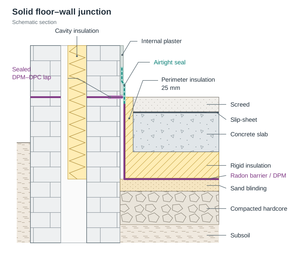
- Hardcore base: Minimum 150 mm thick bed of clean, certified crushed stone (graded 50 mm down to dust, certified to SR21 standards). Where hardcore depth exceeds 225 mm, it must be spread and compacted in successive layers of no more than 225 mm each to guarantee uniform compaction and avoid settlement cracking.
- Sand blinding: 40 mm layer of fine quarry sand rolled over the hardcore to fill voids and form a smooth bed that protects flexible membranes against punctures from sharp aggregate.
- Radon barrier / Damp-Proof Membrane (DPM): A certified gas-resistant polyethylene membrane (typically 400 μm / 1600 gauge). Laid over the blinding, it spans the entire floor footprint, laps through the inner leaf, and is sealed with butyl tape to the horizontal DPC to ensure a continuous barrier against water and gas.
- Thermal insulation: Rigid boards, such as polyisocyanurate (PIR, with thermal conductivity k ≈ 0.022 W/mK) or expanded polystyrene (EPS). Building Regulations TGD L requires a maximum area-weighted average U-value of 0.18 W/m²K for ground floors, or 0.15 W/m²K when the floor includes underfloor heating. Insulation is commonly placed below the structural slab (sub-slab) or directly below an unbonded floating screed.
- Perimeter edge insulation: A vertical 25 mm strip of rigid PIR placed around the entire room perimeter against the inner block leaf. It extends from the horizontal floor insulation up to the top of the screed, eliminating the linear thermal bridge where the cold masonry meets the floor perimeter.
- Airtightness barrier: The membrane or a dedicated airtightness tape is lapped and sealed to the inner wall airtight layer (such as the wet plaster coat, parge coat, or internal membrane). Service penetrations are sealed with flexible neoprene top-hat collar units clamped to pipes.
- Concrete slab: 150 mm C20/25 mass or light mesh-reinforced concrete, compacted, vibrated, and levelled.
- Screed: 65 mm sand-cement screed (1:3 mix) floating over a separating polythene slip-sheet, providing a smooth finish for tiles, timber, or carpet.
Suspended Timber Ground Floors and Hearth Details
Where topsoil is deep, the ground slopes steeply, or fill depths exceed 900 mm, a suspended timber ground floor avoids deep compacted fill.
Construction at the External Cavity Wall Junction
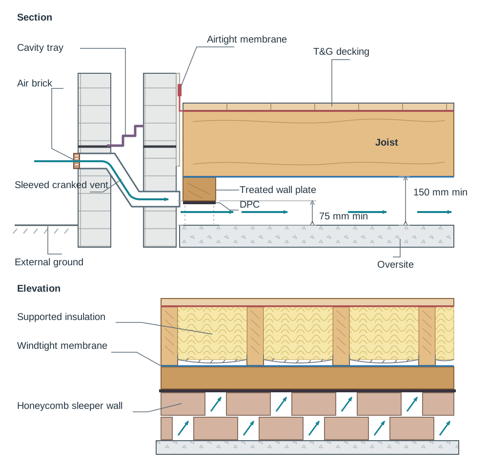
- Oversite concrete: Topsoil is excavated down to subsoil, covered with compacted hardcore, blinded with sand, and sealed with 100 mm of oversite concrete. The oversite surface must sit no lower than the finished external ground level so that water cannot drain into or pool in the void.
- Support and void depth: Joists rest on a preservative-treated wall plate (100 mm x 75 mm) bedded on a continuous horizontal DPC. The plate is supported on sleeper walls built about 50 mm clear of the inner leaf, or joists are hung directly from the inner leaf using galvanised mild steel joist hangers. Joists should never be built directly into the inner leaf, as this breaks the airtight envelope and risks rot. A clear void of at least 75 mm must be kept between oversite concrete and the underside of the wall plate, and at least 150 mm to the underside of the floor joists.
- Sub-floor ventilation: Stagnant air leads rapidly to fungal decay. Sleeper walls are laid in honeycomb bond with quarter- to half-brick gaps between stretchers. Telescopic cranked vents or cavity sleeves pass through the external cavity wall beneath the DPC (protected above by a stepped cavity tray) to connect external air bricks directly to the void, ensuring cross-ventilation.
- Insulation and decking: Breathable mineral wool held in place with netting, or rigid PIR boards supported on treated battens between the 200 mm x 50 mm joists. A vapour-permeable windtight membrane sits beneath the joists, while an airtight membrane covers the top and tapes to the wall plaster. The floor is completed with 22 mm tongue-and-groove (T&G) flooring boards, leaving a 10 mm perimeter expansion gap covered by skirting.
Constructional Hearth Detailing (TGD J)
Where a suspended timber floor meets an open fireplace:
- A constructional hearth made of solid, non-combustible material (such as concrete) must be at least 125 mm thick.
- It must project at least 500 mm in front of the fireplace opening and extend at least 150 mm beyond each side.
- In a suspended timber floor, the hearth is supported from the oversite concrete by brick or block fender walls, or compacted non-combustible fill enclosed by the fender walls.
- Floor joists are trimmed in front of the hearth with a trimmer joist. Combustible timber must not lie within 250 mm beneath the upper surface of the hearth unless separated by a 50 mm air space, and all timber framing must remain at least 200 mm clear of the inside surface of any flue.
Radon Prevention and Detailing (TGD C)
Radon is a naturally occurring radioactive gas produced by the radioactive decay of uranium in underlying subsoils and granitic rock. Tasteless, colourless, and odourless, radon disperses harmlessly outdoors but can reach dangerous concentrations when drawn into airtight dwellings through floor cracks and unsealed service entries. The Irish national reference level for radon in dwellings is 200 Becquerels per cubic metre (200 Bq/m³). Where tests exceed this level, remediation is strongly recommended.
Baseline and High-Radon Protection Measures
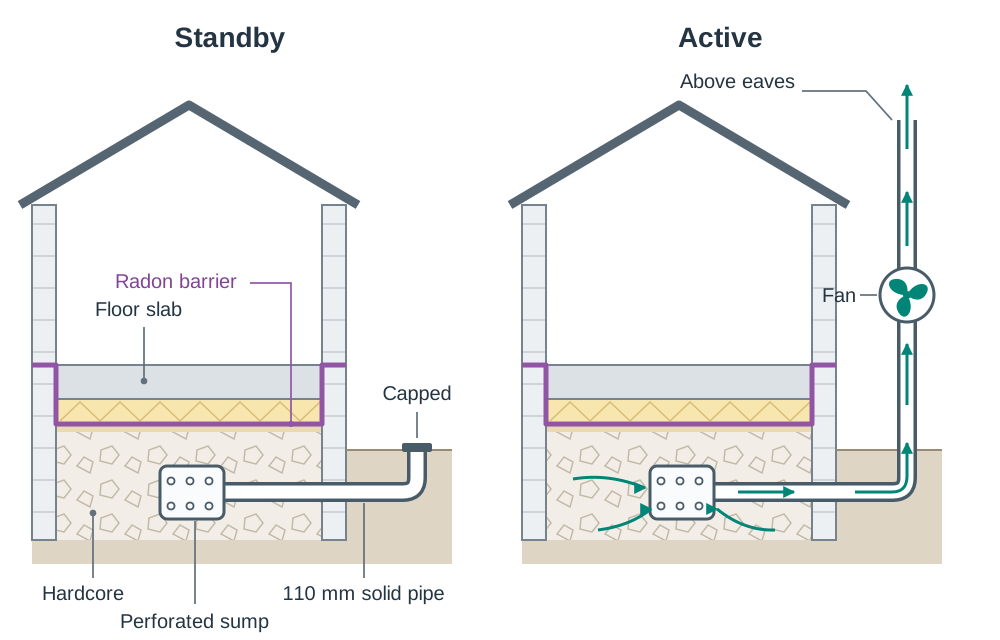
- Standby radon sump (all new dwellings): Irish Building Regulations (TGD C) require every new home to include a standby radon sump set centrally into the clean hardcore bed. The sump is a perforated collector box linked to a continuous 110 mm solid PVC pipe running through the external wall, where it is capped off just outside. The DPM is sealed across the floor to provide a gas barrier.
- High-Radon Areas: Where the Geological Survey of Ireland and EPA designate high-radon risk, a certified heavy-duty radon barrier (400 μm polyethylene reinforced with aluminium or polyester scrim) must be laid across the entire subfloor, dressed through the rising blockwork, and sealed to the wall DPC and cavity trays. Laps must be at least 150 mm wide and bonded with double-sided butyl tape.
- Passive vs active extraction: The capped sump pipe is the passive (standby) system. If post-occupancy testing reveals radon levels above 200 Bq/m³, the external cap is removed and an in-line mechanical extract fan is fitted. This creates an active depressurisation system that draws gas from the sub-slab hardcore and safely vents it above the roof eaves, well away from open windows and trickle vents.
Upper Timber Floors: Framing, Trimming, and Restraint
Upper suspended timber floors carry loads across internal spans, brace external walls, and must provide at least 30 minutes of fire resistance between storeys in typical two-storey domestic buildings.
Joist Support and Lateral Restraint
Floor joists (typically 200 mm x 50 mm or 225 mm x 50 mm at 400 mm centres) span between load-bearing walls. They are supported on the inner leaf by galvanised steel joist hangers or bedded on a treated wall plate. Heavy-duty galvanised mild steel restraint straps (typically 30 mm x 5 mm) tie the floor to masonry walls to provide horizontal bracing. Where joists run parallel to the wall, straps run across at least three joists at no more than 2 m centres, fixed over solid noggings between the joists and turned down 100 mm into the inner block leaf.
Strutting Rules
Slender joists tend to twist laterally or buckle under bending loads. Strutting stiffens the floor, prevents joist rotation, and transfers concentrated loads between neighbours:
- Spans up to 2.5 m: no strutting required.
- Spans from 2.5 m to 4.5 m: one row of strutting at mid-span.
- Spans exceeding 4.5 m: two rows of strutting placed at the third points of the span.
- Solid strutting: timber blocks of the same depth as joists skew-nailed or staggered between joists.
- Herringbone strutting: pairs of crossed 38 mm x 38 mm softwood battens forming an 'X' between joists. This allows pipework to pass easily and remains tight if the joists shrink slightly.
Framing Around Openings (Stairs and Flues)
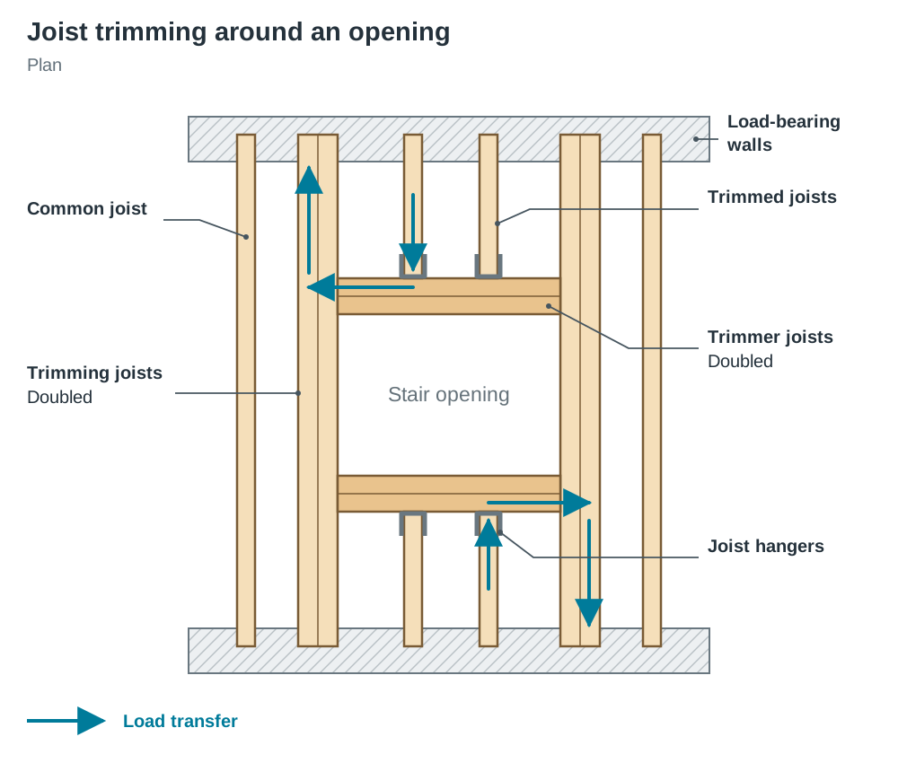
Where joists are interrupted for stairwells or chimney breasts, loads are redirected around the perimeter:
- Trimming joists: full-span joists running parallel to common joists that border the opening and carry the ends of the trimmer. They are strengthened by adding 25 mm thickness (e.g. 200 mm x 75 mm) or by bolting two common joists together.
- Trimmer joists: cross-members spanning perpendicular between the trimming joists to support the cut ends of the interrupted joists. Also sized 25 mm thicker or doubled.
- Trimmed joists: standard joists cut short by the opening, hung from the trimmer joist.
- Traditional joints: traditionally, the trimmer joined the trimming joist with a tusk tenon joint (the tenon at the neutral axis preserves timber strength, while the under-tusk supports the vertical load and a wedge draws it tight). Trimmed joists joined the trimmer using a bevelled housing joint or dovetail housing. In modern construction, heavy-duty galvanised steel joist hangers replace both joints.
Rules for Notching and Drilling Joists
Services passing through upper floors must not compromise joist bending or shear capacity:
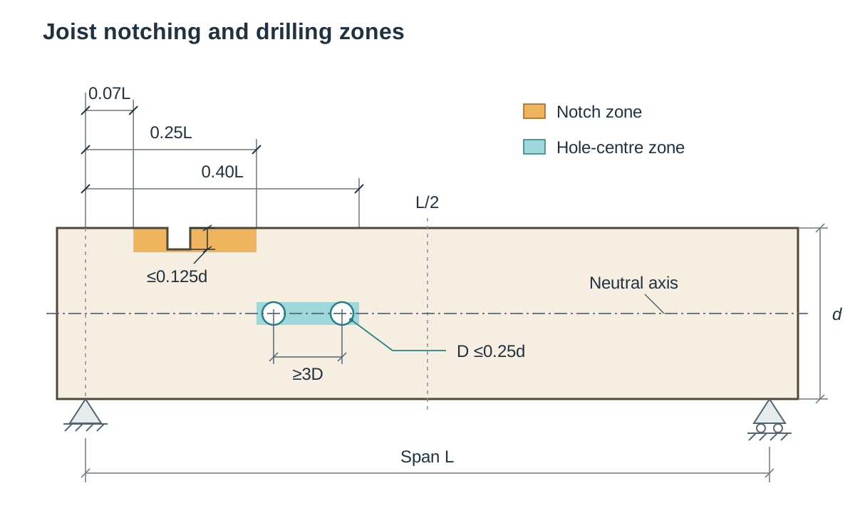
- Notches (for pipes and cables) may only be cut in the top edge of a joist within the zone between 0.07 and 0.25 of the span from the support. Depth must not exceed 0.125 × joist depth.
- Holes must be drilled strictly along the neutral axis (centre line of joist depth) within the zone between 0.25 and 0.4 of the span from the support. Hole diameter must not exceed 0.25 × joist depth, and adjacent holes must be spaced at least three hole diameters apart centre-to-centre.
Floor Decking
Flooring grade 22 mm tongue-and-groove (T&G) chipboard, 18–22 mm OSB3, or 22 mm T&G softwood boards are glued along the tongue-and-groove joints, screwed or ring-shank nailed to every joist, with board ends staggered over joist centres. A 10–15 mm expansion gap is left around the perimeter.
Sound Insulation of Upper Floors
Building Regulations TGD E specifies mandatory acoustic performance for separating floors between different dwellings (such as apartments). Within single-family domestic dwellings, these same acoustic design principles are applied to ensure privacy and comfort between storeys.
Sound transmits through floors via two mechanisms:
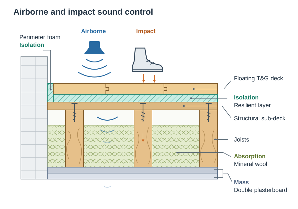
- Airborne sound: voices, television, and music travel through the air and vibrate the structure. Airborne sound is controlled by mass and absorption. Dense materials, such as double layers of 12.5 mm or 15 mm plasterboard fixed to the ceiling below, resist sound passage. High-density mineral wool insulation (minimum 100 mm) placed between the joists absorbs reverberant acoustic energy inside the floor void.
- Impact sound: footsteps, dropped objects, and vibrating appliances strike the floor directly, transmitting sound mechanically through joists. Impact sound is controlled by structural isolation using a floating floor. A resilient layer—such as high-density mineral wool batts or closed-cell foam strips—is laid over the joists or sub-deck. The finished T&G timber deck is laid unbonded on top, with no mechanical screw or nail fixings bridging down into the supporting joists, and isolated from perimeter walls using flexible foam strips.
Domestic Floor Coverings and Selection
Floor coverings provide the final wearing surface. Selection depends on foot traffic, moisture resistance, maintenance, and compatibility with underfloor heating.
| Finish Type | Common Applications | Key Characteristics | Substrate & Fixing Method |
|---|---|---|---|
| Ceramic / Porcelain Tiles | Kitchens, bathrooms, hallways | Highly durable, completely waterproof, easy to clean; excellent thermal conductivity for underfloor heating | Bedded in flexible tile adhesive over fully cured screed or cement backer boards; grout lines sealed |
| Solid Hardwood (Oak, Beech) | Living rooms, reception areas | Premium natural appearance, long lifespan as it can be repeatedly sanded and refinished; vulnerable to moisture and cupping | Secret-nailed through the tongue into joists or timber battens; requires a 15 mm perimeter expansion gap |
| Engineered Timber / Laminate | Bedrooms, dining rooms, upper hallways | Multi-ply construction provides high dimensional stability, resisting warping from temperature changes | Installed as a floating floor over closed-cell acoustic foam underlay; click-locked or glued at joints |
| Sheet Vinyl & Linoleum | Utility rooms, wet areas, bathrooms | Continuous impervious surface, hygienic, resilient, and quiet underfoot; low maintenance | Fully bonded using contact adhesive onto smooth screed or marine-grade plywood underlayment |
| Carpet & Underlay | Bedrooms, living rooms, stairs | High impact sound absorption, warm and comfortable underfoot; absorbs liquid spills and stains easily | Stretched over dense rubber or foam underlay and anchored with perimeter gripper rods |
Key terms
- Capillary Action
- The movement of water through narrow microscopic pores in subsoil and porous masonry, allowing moisture to rise against gravity unless broken by an impermeable membrane or coarse granular fill.
- DPC
- Damp-Proof Course; a continuous strip of impermeable material (such as bitumen or heavy polyethylene) built into wall courses at least 150 mm above ground level to prevent rising damp.
- Radon Sump
- A perforated plastic collector unit embedded centrally within the hardcore beneath a ground floor slab, fitted with pipework to allow passive or fan-powered active venting of radon gas.
- Top-Hat Collar
- A prefabricated flexible neoprene sleeve fitted and clamped around pipe penetrations through a radon barrier or DPM to maintain a completely airtight, gas-tight seal.
- Thermal Bridge
- A localised path of high thermal conductivity across an insulated building envelope—such as where a floor slab meets an uninsulated inner masonry leaf—causing heat loss and condensation.
- Honeycomb Bond
- A brick or block bonding pattern used in sub-floor sleeper walls that leaves open spaces between stretchers to ensure continuous cross-ventilation through the floor void.
- Constructional Hearth
- A non-combustible solid hearth (minimum 125 mm thick) projecting at least 500 mm in front and 150 mm to the sides of a fireplace opening to isolate the structure from heat and embers.
- Joist Hanger
- A pressed galvanised steel bracket fixed to a wall or timber beam to support the ends of floor joists without needing to build timber directly into masonry.
- Trimming Joist
- A full-span floor joist running parallel to common joists that carries the concentrated load from the ends of a trimmer joist, sized 25 mm thicker or doubled.
- Trimmer Joist
- A cross-member spanning perpendicular across an opening between trimming joists to support the cut ends of trimmed joists.
- Trimmed Joist
- A common floor joist shortened by an opening (such as a stairwell or hearth) and carried by a trimmer joist.
- Floating Floor
- A floor deck surface supported on a resilient acoustic underlay without any mechanical nail or screw fixings into the structural joists, isolating impact sound.
Check yourself
What are two advantages of using a suspended timber ground floor instead of a solid concrete floor on a sloping site?
It eliminates the need for deep hardcore fill exceeding 900 mm (which risks settlement cracking), and it avoids long drying delays, providing a dry, easily piped sub-floor void.
What is the maximum permissible diameter for a service hole drilled in an upper floor joist, and where along the joist must it be located?
The diameter must not exceed 0.25 times the joist depth. It must be drilled on the centre line of the joist between 0.25 and 0.4 of the span from a support.
What are the row requirements for joist strutting across different floor spans?
Spans up to 2.5 m need no strutting; spans between 2.5 m and 4.5 m require one row at mid-span; spans over 4.5 m require two rows placed at the one-third span points.
What is the primary method used to reduce impact sound transmission in an upper timber floor?
Installing a floating floor, where the floor deck is laid over a resilient acoustic isolating layer without mechanical fixings penetrating down into the structural joists.
What are the minimum dimensions of a constructional hearth in front of and to the sides of an open fireplace opening?
It must be at least 125 mm thick, project at least 500 mm in front of the opening, and extend at least 150 mm beyond each side.