
Fireplace and chimney construction is examined in two distinct ways in Leaving Certificate Construction Studies: as an accurate, scaled vertical section in the compulsory drawing question, and as written theory in construction-theory questions covering flue aerodynamics, fire spread, BS 476 furnace testing, and Building Regulations (Technical Guidance Documents Part B and Part J). An open fire looks simple, but the fireplace and chimney have to do three jobs at once: stand up, keep fire and intense heat away from the timber structure, and pull combustion gases reliably out through the roof. Every dimension and clearance in this topic exists to satisfy one of those three requirements.
Fireplace Anatomy, Airflow, and Flue Sizing
(Note: This material is examined both as technical drawing details in the compulsory drawing question and as written theory in construction-theory questions.)
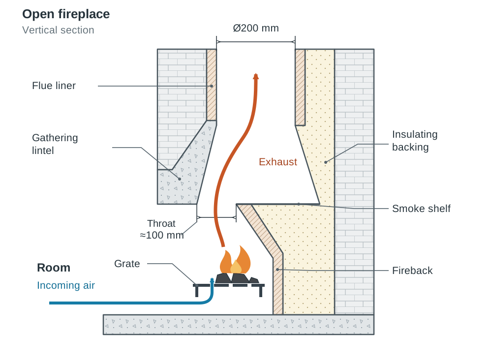
An open fireplace relies on natural convection to draw air through the fuel bed and carry combustion gases safely out of the house. Cool room air enters the base of the fire through the grate, which lifts the solid fuel to supply under-draught. As fuel burns, hot exhaust gases become buoyant and rise.
Internal Components
- Fireback: Formed from precast fireclay or refractory concrete, shaped with a forward-sloping back. This slope radiates heat directly forward into the room rather than allowing it to soak into the backing masonry. The hollow space behind the fireback is filled with an insulating weak mix (typically 1:1:12 cement, lime, sand) or vermiculite, which absorbs thermal expansion without cracking surrounding walls.
- Throat: Directly above the fireback, the opening is deliberately narrowed to form the throat, restricted to approximately 100 mm. Narrowing the opening forces the rising hot gas through a smaller space, so it speeds up. The faster the gases move, the better the fire draws and the less likely smoke is to roll back into the room. A precast concrete flue-gathering lintel spans the opening to funnel exhaust gases smoothly into the flue liner.
- Smoke shelf: A flat horizontal ledge directly behind the throat. When cold outside air descends the chimney, the smoke shelf catches that downdraught and deflects it back upward into the hot exhaust stream, preventing smoke and carbon monoxide from puffing into the living space.
Flue Sizing
The flue must match the size of the fire opening. The design rule of thumb requires the cross-sectional area of the flue to be about one-seventh (roughly 15%) of the area of the fireplace opening. For a standard domestic fireplace opening up to 500 mm wide, this requires a circular flue liner of at least 200 mm internal diameter.
- Flue too large: Rising gases expand, slow down, and cool rapidly. They lose thermal buoyancy, leading to poor draught, heavy tar and soot deposits, and smoke spillage into the room.
- Flue too small: The opening cannot discharge combustion products fast enough, choking the fire and forcing smoke back into the room.
Combustion Air Supply (TGD J1)
A fire burns room air. If that air is not replaced, the room depressurises, the chimney cannot draw, and incomplete combustion produces deadly carbon monoxide (CO). TGD J1 requires every room with an open fire to have a permanently open air vent with a free area of at least 50% of the cross-sectional area of the flue. For a 200 mm diameter flue (area ), this requires a permanent vent of at least (roughly clear opening).
In modern, highly insulated and airtight NZEB homes, an open wall vent creates unacceptable heat loss and draughts. The modern solution is a room-sealed stove fed by a dedicated direct external air pipe through the external wall or floor, keeping the airtight membrane intact.
Open Fire versus Closed Stove
Traditional open fires have an efficiency of only 20% to 30%, as roughly 75% to 80% of heat escapes up the chimney while pulling preheated room air out of the building. By contrast, a closed stove operates at 70% to 80% efficiency, provides adjustable air controls, and prevents room air loss when unlit.
Hearth Detailing, Timber Clearances, and Drawing Order
(Note: This detail is examined as a dimensioned sectional drawing in the compulsory drawing question.)
Where an open fireplace meets a suspended timber floor or roof, heat can travel by conduction through masonry and set fire to any timber touching it. Timber must never touch or run under the active fireplace structure.
The Hearth Assembly
Building Regulations TGD J requires a two-part hearth:
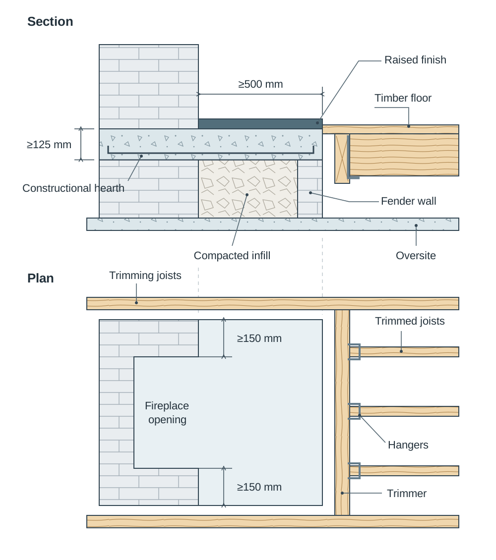
- Constructional hearth: A solid reinforced concrete slab at least 125 mm thick. In suspended timber ground floors, it cannot rest on timber floor joists. Instead, it is built off dwarf fender wall sleeper foundations (100 mm blockwork built off the oversite concrete) backfilled with compacted hardcore or mass concrete, or cantilevered from the chimney breast foundation. It must project at least 500 mm in front of the chimney breast and at least 150 mm beyond each side of the fireplace opening.
- Superimposed hearth: A decorative non-combustible finish (slate, marble, granite, or tile, typically 25 mm to 50 mm thick) bedded on the constructional slab. It is laid slightly proud of the floorboards so that its raised edge forms a kerb against rolling embers and clearly marks the hearth boundary so combustible flooring is not laid across it.
Framing Suspended Timber Floors
The floor joists are framed around the hearth zone:
- Trimming joists: The two full-length joists running in the normal joist direction on either side of the hearth opening. They carry the trimmer and are made one size heavier (usually 25 mm thicker) than common joists to support the concentrated loads.
- Trimmer joist: A heavier cross-member spanning perpendicular between the two trimming joists along the front edge of the constructional hearth, supporting the ends of the shortened common joists (trimmed joists) on galvanised steel hangers.
Statutory Timber Clearances
- 200 mm rule: No combustible material (joists, rafters, wall plates, or battens) may be within 200 mm of the inside surface of any flue or the inner face of the fireback.
- 40 mm rule: No structural timber may be within 40 mm of the outer masonry surface of the chimney breast or stack. Exception: Thin room finishes (floorboards, skirtings, architraves, mantel shelves, picture rails) may butt against the outer masonry, provided they remain outside the 200 mm zone from the flue.
- Metal fixings: Any metal fixing in contact with timber (such as a joist hanger) must remain at least 50 mm clear of the inside surface of the flue.
Framing at Roof Level
Where the chimney passes through ceiling joists and rafters, the same 200 mm and 40 mm clearances apply. Trimming rafters carry a trimmer rafter clear of the stack. Non-combustible mineral wool is packed into the 40 mm air gap, and the ceiling void is closed with non-combustible board and fire-stopped.
Question 1 Drawing Sequence
To draw a vertical section through a ground-floor fireplace efficiently, follow this order:
- Base: Draw the sub-base, oversite concrete, and damp-proof membrane (DPM).
- Breast: Draw the 200 mm solid blockwork chimney breast and foundation.
- Hearth base: Draw 100 mm fender walls, hardcore infill, and the 125 mm reinforced constructional hearth projecting 500 mm in front.
- Firebed: Position the fireclay fireback on refractory mortar, draw the 1:1:12 insulating weak mix behind it, and add the grate.
- Gathering: Draw the throat (approximately 100 mm), the smoke shelf, and the concrete flue-gathering lintel.
- Flue: Draw the first 200 mm clay flue liner with its socket pointing upwards, surrounded by lightweight insulating backfill.
- Floor junction: Draw the trimmer joist on galvanised hangers at the front of the hearth, showing the 40 mm masonry clearance and 200 mm flue clearance.
- Finishes: Add the superimposed hearth, floorboards, DPC, and screed, then apply standard hatching and labels.
Flue Runs, Terminations, and Roof Weatherproofing
A domestic flue must be built as vertical as possible to provide a smooth, fast draught. Where an offset cannot be avoided (such as directing a stack to the ridge), no bend may exceed to the vertical. Every bend creates turbulence, slows exhaust gases, and collects soot and tar, increasing the risk of chimney fires. Access doors for sweeping must be provided at offsets.
Flue liners must be installed rebated socket uppermost and jointed with fireclay or refractory mortar. When liquid condensate or acidic soot runs down inside the flue, the upward-facing socket keeps the liquid within the pipe rather than letting it seep into the brickwork. Liners must never be bonded rigidly to the outer masonry; thermal movement is accommodated by filling the surrounding space with a weak dry mix of cement, lime, and sand (1:1:12) or exfoliated vermiculite.
Termination Height Rules
To prevent turbulent wind eddies over the roof from forcing downdraughts down the flue, chimneys must meet strict dimensional rules:
- Total Flue Height: Minimum 4.5 metres measured vertically from the hearth to the flue terminal.
- Termination on Roof Slope: The top of the pot must extend at least 1.0 metre vertically above the highest point of intersection with the roof covering.
- Termination at Ridge: If the stack breaches the roof within 600 mm of the ridge line, it must extend at least 600 mm vertically above the ridge.
- Wind Stability: To prevent wind gusts overturning a freestanding stack, its maximum height above the roof () must not exceed 4.5 times its least horizontal width (): .
Roof Abutment Weatherproofing
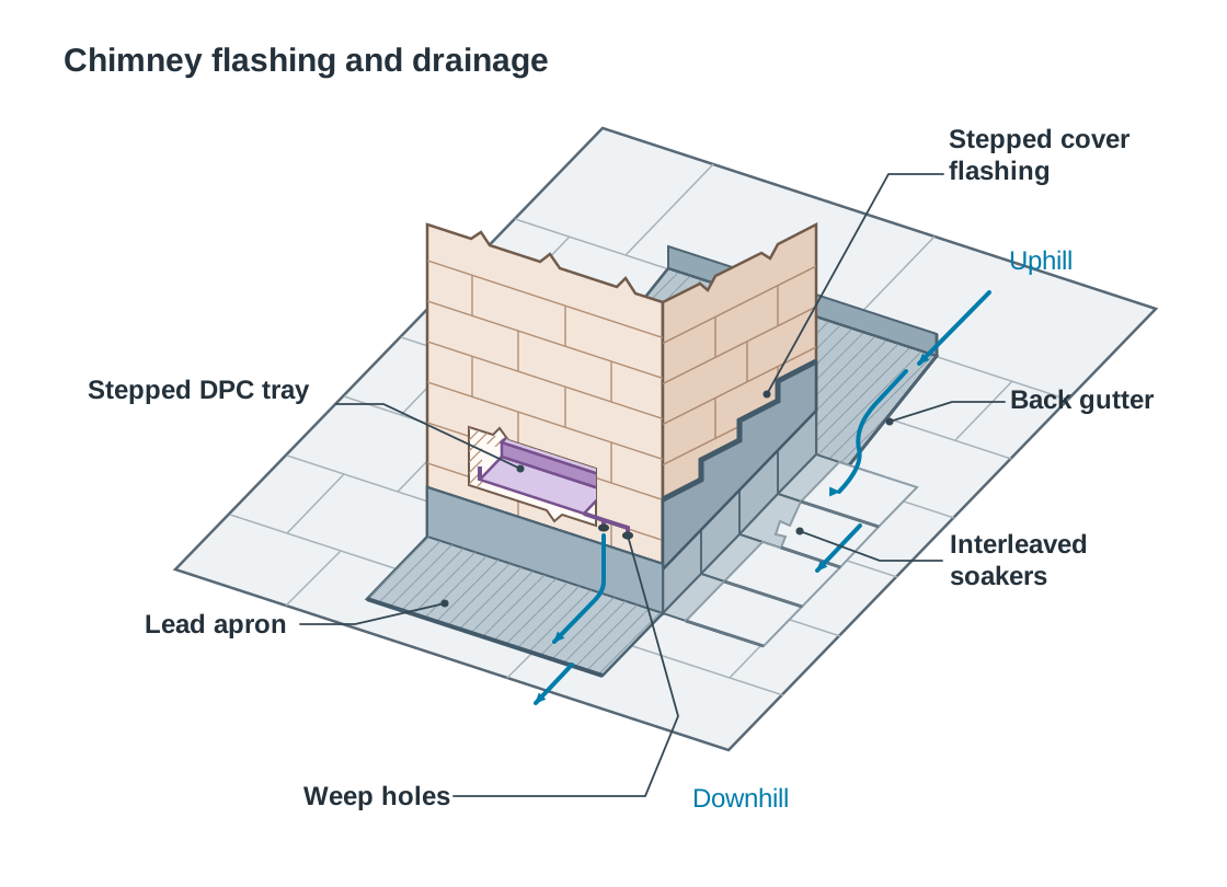
Where the masonry punches through the roof covering, water entry is prevented by multi-part lead flashings (Code 4 or Code 5 lead sheet) working with a stepped DPC:
- Lead apron (front): Fitted across the downhill face, turned up 75 mm against the brickwork and dressed at least 150 mm over the roof slates or tiles.
- Soakers and step flashings (sides): Right-angled lead soakers are interwoven with each slate course (extending 100 mm under slates and 75 mm up the stack). A stepped cover flashing is chased 25 mm into the mortar bed joints with lead wedges and pointed, lapping down over the soakers.
- Back gutter (rear): Positioned behind the uphill face of the stack. A timber gutter board on tilted firrings forms a channel with a minimum 100 mm vertical upstand behind the masonry, catching descending rainwater and shedding it safely to the side gutters.
- Stepped DPC tray: Built into the chimney masonry courses just above the roofline. It features raised lips and weep holes discharging onto the lead apron, catching rain percolating down through porous brickwork.
- Flaunching and capping: A weathered mortar flaunching sloped outward at or a precast concrete capping with a drip groove sheds rain clear of the top masonry courses.
Fire Dynamics and Building Fire Spread
(Note: This material is examined as written theory in construction-theory questions.)
A fire requires three components simultaneously: fuel, oxygen, and heat. This is the fire triangle. Removing any one element extinguishes the fire—water absorbs heat, a fire blanket starves oxygen, and closing internal doors limits oxygen and isolates fuel.
Methods of Fire Spread
In domestic dwellings, fire and smoke spread through four distinct mechanisms:
- Conduction: Heat travels through solid building components. Structural steel beams, copper pipework, or uninsulated flues carry heat directly through walls, igniting timber on the other side. This is why structural timber must remain 200 mm clear of flue interiors and 40 mm clear of chimney masonry.
- Convection: Heated air and smoke expand, become buoyant, and rise rapidly. Convection is the leading cause of death in domestic fires. Hot smoke and toxic gases surge up open stairwells, filling upper landings and bedrooms. Building regulations require protected stairways, self-closing doors, and linked smoke alarms to counteract convection.
- Radiation: Heat travels as electromagnetic infrared waves through the air without direct contact, heating nearby surfaces to ignition temperature. Radiant heat can jump across room boundaries or ignite an adjacent house across a site boundary, which is why TGD B4 regulates boundary separation distances.
- Direct burning (flame contact): Flames travel along continuous runs of combustible materials, such as suspended timber floor voids, stud partitions, or cavity insulation. To halt direct flame spread, cavity barriers are installed at wall-floor junctions, and fire stopping seals service penetrations through walls and ceilings.
BS 476 Fire Testing and Performance Criteria
Fire safety specifications depend on standard testing procedures under the British Standard 476 series.
Reaction to Fire versus Fire Resistance
- Reaction to fire (materials): Tests how an individual material behaves when ignited and contributes to fire growth. BS 476 Part 7 measures the Surface Spread of Flame, ranking materials from Class 1 (best performance, lowest flame spread, such as gypsum plasterboard) to Class 4 (worst performance, rapid flame spread, such as untreated fibreboard). Remember: low number, low spread.
- Class 0: This is not an individual BS test. It is a high-performance designation under Irish Building Regulations earned when a material achieves a Class 1 spread of flame under BS 476 Part 7 and passes the strict fire propagation index under BS 476 Part 6.
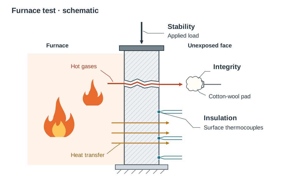
- Fire resistance (elements of structure): Evaluates how a complete, assembled structural element (such as a timber stud wall, floor, or fire door) performs over time inside a standardised testing furnace (BS 476 Parts 20–22), rated in minutes (30, 60, 90, or 120).
The Three BS 476 Performance Criteria
When an element is tested in a furnace, examiners look for three distinct criteria. Use this simple memory hook:
- Stability: Does it stay up?
- Integrity: Does it keep fire and hot smoke on the furnace side?
- Insulation: Is the unexposed side cool enough not to ignite nearby furnishings?
Formally defined:
- Stability: The element carries its full structural design load during fire exposure without structural collapse.
- Integrity: The element prevents flames or hot gases from passing through cracks or openings. Integrity fails if continuous flaming occurs on the unexposed face, if a standard cotton-wool pad held over a fissure ignites, or if a 6 mm gap gauge penetrates a crack and moves 150 mm along it (or a 25 mm gauge penetrates freely at any point).
- Insulation: The element restricts heat transfer to the unexposed face. Insulation fails when the average temperature rise on the unexposed cold face exceeds above ambient, or when any single thermocouple measures a rise exceeding .
Statutory Building Regulations: TGD Part B and Part J
Irish domestic construction must comply with the Building Regulations Technical Guidance Documents.
Technical Guidance Document B (Fire Safety)
TGD B sets out five core functional safety requirements:
- B1 (Means of Escape): Occupants must be able to escape safely. Upper floors require protected stairways and bedroom escape windows. An escape window must provide an unobstructed openable area of at least , with minimum dimensions of 450 mm 450 mm, and a maximum cill height of 1100 mm above finished floor level (to allow easy exit). Early warning requires mains-powered, interlinked smoke and heat alarms.
- B2 (Internal Fire Spread — Linings): Internal wall and ceiling finishes must inhibit flame spread. Circulation spaces and protected escape stairs require Class 0 linings, while individual habitable rooms may use Class 1.
- B3 (Internal Fire Spread — Structure): Buildings must maintain structural stability during fire. Compartment party walls between semi-detached or terraced dwellings must achieve at least 60 minutes fire resistance, extending completely to the underside of non-combustible roof slates. Openings into integral garages require 30-minute fire-resisting partition walls and self-closing FD30S fire doors (with smoke seals). Cavity barriers and fire stopping seal hidden voids.
- B4 (External Fire Spread): External walls and roofs must resist ignition and prevent fire spreading across site boundaries, controlled by adequate boundary separation.
- B5 (Access and Facilities for the Fire Service): Adequate roadway access and clear perimeter space must be provided for fire engines and equipment.
Technical Guidance Document J (Heat Producing Appliances)
- J1 (Air Supply): Solid-fuel appliances must have a permanent combustion air supply (vent free area of flue area) to ensure clean burning and prevent carbon monoxide accumulation.
- J2 (Discharge of Combustion Products): Chimneys and flues must safely vent exhaust outside without downdraught or gas spillage.
- J3 (Protection of the Building): Floors, walls, and roofs must be protected from high temperatures by providing a 125 mm constructional hearth, firebacks, and strict clearances (200 mm to flue interiors, 40 mm to outer masonry). A dedicated carbon monoxide (CO) alarm is mandatory in every room containing a fixed fuel-burning appliance.
Key terms
- Fireback
- A refractory fireclay or concrete unit lining the back and sides of an open fireplace, shaped with a forward slope to radiate heat into the room.
- Throat
- The deliberate constriction (approximately 100 mm wide) between the top of the fireback and the gathering lintel that accelerates smoke into the flue.
- Smoke Shelf
- A horizontal ledge located behind the throat that arrests cold downdraughts and rolls them upward into the rising exhaust stream.
- Flue-gathering Lintel
- A precast concrete lintel spanning the fireplace jambs, shaped to funnel flue gases smoothly from the open fireplace into the circular flue liner.
- Constructional Hearth
- A reinforced concrete slab at least 125 mm thick that isolates the floor structure from heat, projecting at least 500 mm in front of the breast and 150 mm beyond the jambs.
- Superimposed Hearth
- A decorative non-combustible finish (slate, tile, or granite) laid over the constructional hearth, sitting proud of the timber floor to create an ember kerb.
- Fender Wall
- A 100 mm masonry sleeper wall built off the oversite concrete around the hearth zone to retain compacted infill and support the constructional hearth.
- Trimming Joist
- A full-length floor joist on either side of the hearth opening that carries the trimmer; it is made one size thicker to carry the transferred loads.
- Trimmer Joist
- A heavy cross-member framed between two trimming joists along the front edge of the hearth to support the cut ends of the trimmed joists.
- Flue Liner
- A circular refractory clay or concrete pipe (minimum 200 mm internal diameter for an open fire) installed socket uppermost to carry combustion products safely.
- Soaker
- A sheet-lead angle piece interwoven between consecutive courses of roofing slates against the chimney masonry to prevent lateral water penetration.
- Back Gutter
- A lead-lined timber trough built behind the uphill face of a chimney stack to catch roof runoff and divert it around the sides of the masonry.
- DPC Tray
- A stepped damp-proof barrier built into chimney masonry courses above the roofline with weep holes that discharge percolating moisture outward onto flashings.
- Flaunching
- A weathered mortar finish sloped outward at 45 degrees around the chimney pot to shed rain off the top of the masonry stack.
- Fire Resistance
- The ability of an assembled building component to maintain stability, integrity, and insulation for a certified period (in minutes) during a standard furnace test.
- Stability
- The failure criterion under BS 476 measuring whether a load-bearing element continues to carry its structural load during fire exposure without collapsing.
- Integrity
- The failure criterion under BS 476 evaluating whether cracks allow flames or hot gases to pass through, tested by the ignition of a cotton-wool pad or gap gauges.
- Insulation
- The failure criterion under BS 476 measuring heat conduction, breached if the unexposed surface rises more than 140°C on average or 180°C at any single point.
- Class 0
- An Irish Building Regulations lining classification requiring Class 1 surface spread of flame under BS 476 Part 7 and a low fire propagation index under Part 6.
- Cavity Barrier
- A fire-resisting barrier placed across a concealed cavity void to stop the unseen passage of smoke and direct flame spread.
- Fire Stopping
- A non-combustible, fire-resisting seal installed around pipes, cables, or joints where services breach fire-separating floors or walls.
Check yourself
What is the typical design width of the throat opening between the fireback and the flue-gathering lintel?
Approximately 100 mm—the opening is deliberately restricted to this width to accelerate exhaust gases.
State the minimum thickness and forward projection required for a concrete constructional hearth.
A minimum thickness of 125 mm and a forward projection of at least 500 mm in front of the chimney breast.
What are the statutory clearance distances from combustible structural timber to the inside of a flue and to the outside of chimney masonry?
At least 200 mm from the inside surface of the flue or fireback, and at least 40 mm from the outer chimney masonry.
State the permanent ventilation free area required for an open fire served by a 200 mm diameter flue.
At least 50% of the cross-sectional area of the flue, which equals roughly 15 700 mm².
Name the heat transfer mechanism by which fire most often spreads from a ground-floor room to an upper landing, and one TGD B measure that resists it.
Convection (rising hot smoke and toxic gases). Resisted by a protected stairway, self-closing fire doors, and interlinked mains-powered smoke alarms.
A roofer installs an apron flashing and side step flashings to a chimney on a 35° roof, but leaves out the back gutter. Describe what happens.
Rain running down the roof pitch ponds behind the stack, soaks through porous brickwork, and leaks through the ceiling below. The back gutter is essential to divert water around the sides.
What are the temperature rise failure limits for the Insulation criterion during a standard BS 476 furnace test?
An average cold-face temperature rise exceeding 140°C above ambient, or any single thermocouple measuring a rise exceeding 180°C.
What is the maximum cill height for an emergency escape window under TGD B?
A maximum of 1100 mm above finished floor level (with a minimum openable area of 0.33 m² and minimum dimensions of 450 mm × 450 mm).