
A window has two jobs to learn about in Leaving Certificate Construction Studies, and the examination tests both. First, it is a hole in the external wall that must be detailed correctly: the wall above must be carried, rain kept out, insulation run continuously past the frame, and the air seal maintained without cold bridging. Second, it is an optical aperture that admits natural daylight and fresh air, both of which can be measured, calculated, and regulated. At Higher Level, you need to master both halves: the structural joinery and sectional drafting of heads, cills, and jambs in masonry and timber-frame walls, alongside the environmental science of illumination, photometric units, the CIE standard overcast sky, daylight factor calculations, and glare control.
Window Functions, Regulations, and Selection Factors
A window opening in an external wall is a critical element of the building envelope. Because external walls achieve high thermal resistance, window openings represent the greatest risk for heat loss, air leakage, and surface condensation.
Primary Envelope Functions
- Daylighting and solar gain: Admits visible daylight to reduce artificial lighting and harvests passive solar heat gain during the heating season, particularly through south-facing glazing.
- Thermal retention: Resists conductive, convective, and radiant heat loss. The whole-window thermal transmittance () accounts for the glass, spacer bars, and frame profile combined.
- Ventilation: Provides rapid purge ventilation through opening sashes to exhaust indoor water vapour, cooking odours, and volatile organic compounds (VOCs), complemented by background ventilation.
- Sound insulation: Reduces traffic and outside noise. This is improved by airtight perimeter seals, by using two panes of different thickness (so they do not resonate at the same frequency), by a wider gas cavity, and by laminated glass.
- Life safety and escape: Provides an emergency escape route for occupants during a fire while enabling rescue access.
Regulations and Design Rules of Thumb
- Daylight provision: As a design rule of thumb, aim for a glazed area of at least of the floor area in a habitable room, rising to in rooms where close work is done, such as kitchens and studies. This is design guidance rather than a statutory minimum.
- Purge ventilation (TGD Part F): An openable window area of at least () of the floor area of the room, designed for rapid removal of moisture and pollutants.
- Background ventilation (TGD Part F): A permanent, controllable opening such as a frame-mounted trickle vent or a wall vent. In naturally ventilated dwellings, the figure usually quoted for a habitable room is about equivalent area (less for kitchens and bathrooms). In a naturally ventilated house these vents must never be blocked up by occupants. However, in an airtight nZEB or passive house served by a mechanical ventilation with heat recovery (MVHR) system, trickle vents are deliberately omitted; continuous filtered fresh air is supplied mechanically, and any unsealed hole in the envelope would defeat the heat recovery.
- Emergency egress (TGD Part B): An escape window is required to each habitable room in a storey whose floor is not more than above ground level (in practice, first-floor bedrooms and inner rooms). It must provide an unobstructed openable area of at least , with minimum clear dimensions of high and wide. The bottom of the openable area must be not more than above finished floor level (FFL), and commonly at least above the floor to avoid creating a fall hazard. Any restrictor or lock fitted to an escape window must be openable from inside without a key or special tool.
Applied Scenario: Bedroom Opening Checks
Consider a first-floor bedroom measuring ( floor area):
- Target glazed area ( rule of thumb): .
- Purge ventilation requirement ( of floor area): openable.
- Escape check on an openable sash measuring : width and height both exceed , and the clear area is . Because , it passes escape rules. However, on its own it does not meet the purge ventilation requirement, meaning an additional opening sash or a larger casement is needed.
Factors Affecting the Choice of a Window
When answering a Section B question on selecting windows, pair each factor with its practical reason:
- Function and room use: A kitchen or study needs more light and higher purge ventilation than a hallway or utility room.
- Daylight requirement: Glazed area relative to floor area, and window head height, which dictates how deep light penetrates into the room.
- Orientation: Generous glazing to the south captures passive winter solar gain; restricted glazing to the north minimises heat loss. South and west elevations require shading to prevent summer overheating.
- Thermal performance: Whole-window U-value, warm-edge spacer bars, and thermally broken frames.
- Means of escape and safety: Escape compliance in upper bedrooms, restrictor stays to prevent falls, and safety glass in critical locations.
- Security: Multi-point espagnolette locking systems and laminated glass on accessible ground-floor windows.
- Maintenance and durability: Low-maintenance uPVC or alu-clad systems versus timber that requires repainting every 4 to 6 years.
- Capital cost versus life-cycle cost: High initial outlay for alu-clad triple glazing versus lower lifetime heating bills and zero redecoration expense.
- Appearance and proportion: Matching the architectural character, sightlines, and proportions of the house. In a protected structure or Architectural Conservation Area (ACA), planning authorities normally insist on like-for-like timber joinery.
Window Typologies, Component Parts, Ironmongery, and Workshop Joinery
Window Typologies
- Casement windows: Sashes are hinged at the side (side-hung) or top (top-hung/awning) and swing outward, closing against continuous compression gaskets.
- Vertical sliding sash windows: Sashes slide vertically in recessed channels within a boxed frame, counterbalanced by cast-iron or lead weights hung on sash cords over brass pulleys, or by modern spiral spring balances. Meeting rails, parting beads, and staff beads require brush-pile seals to prevent draughts.
- Pivot windows: The sash turns on pivots fixed at the centre of the jambs (vertical pivot) or the head and cill (horizontal pivot). It swings through up to , allowing the outside face of the glass to be cleaned safely from inside the room, which makes it ideal for rooflights and high elevations.
Named Parts of a Timber Casement Window
Learn these terms for annotating Question 1 sectional drawings:
The Frame (the fixed outer surround built into the wall opening):
- Head: The top horizontal member of the frame.
- Jambs: The two vertical side members of the frame.
- Cill: The bottom member, machined with an outward slope (the weathering, roughly or 1:6) to shed water. Its underside contains a throating / drip groove so water drops clear instead of tracking back to the wall.
- Water bar: A galvanised steel or hardwood strip bedded in mastic inside a groove in the timber cill to stop wind-driven rain being blown under the sash.
- Mullion: A vertical dividing post between two window lights.
- Transom: A horizontal dividing rail; an opening light above a transom is called a fanlight or ventlight.
- Rebate: The machined step in the frame against which the sash closes, usually deep.
The Sash (the opening glazed frame):
- Stiles: The vertical outer members of the sash.
- Top rail and bottom rail: The horizontal members of the sash.
- Meeting stile: Where two opening sashes close together.
- Glazing bar: Slender timber bar dividing the sash into smaller panes.
- Capillary groove: A narrow groove machined along the rebate or sash edge to break the capillary action that would otherwise pull water inward.
- Horn: A small projection left on a sash or frame stile to protect the joint during transit and strengthen the mortise.
- Fixed light: A glazed panel fitted directly into the frame without an opening sash.
Ironmongery (the metal fittings that make the window work):
- Butt hinges: Two- or three-knuckle hinges for a traditional side-hung casement.
- Friction stays: Stainless steel hinge-stays that hold a top- or side-hung sash open at any position against wind.
- Casement stay and peg: A metal bar fixed to the sash that drops onto pins on the cill to hold the casement open at set positions.
- Casement fastener (cockspur or espagnolette handle): A lever handle that pulls the sash tight against the frame weather seal when closed.
- Multi-point locking gear: Cams and shootbolts driven by one handle to lock the sash at several points around the frame for security.
- Restrictor stay: Limits initial opening to about 100 mm so a child cannot fall out — on a designated escape window it must release from inside without a key or tool.
- Trickle vent: A controllable background ventilator built into the head of the frame.
Workshop Joinery Processes
In traditional timber joinery, frames and sashes must remain square and resist moisture movement:
- Setting-out rod: A full-size drawing on a timber board showing exact lengths, mortise-and-tenon shoulders, rebates, and sightlines to ensure accuracy.
- Face marks and face edges: Timber components are planed flat and square. Face marks and edge marks provide consistent reference datum lines for all mortise gauges.
- Haunched mortise and tenon: Rails and stiles are joined with a haunched mortise and tenon. The haunch fills the rebate groove at the corner, preventing light and water leaks while stopping the joint from twisting.
- Testing diagonals: During dry clamping, diagonals are measured across opposite corners; identical diagonal measurements prove the frame is perfectly square.
- Gluing and wedging: The frame is assembled with waterproof adhesive (Class D4 PVA or polyurethane), clamped square, wedged, pinned with dowels, and treated with preservative before glazing.
Frame Materials, Types of Glass, and Glazing Systems
Frame Materials Compared
| Framing Material | Advantages | Disadvantages |
|---|---|---|
| Timber (Hardwood / Treated Softwood) | Natural insulator, low embodied carbon, traditional appearance, easily repaired. | Needs periodic painting, staining, or preservative treatment. |
| uPVC (Unplasticised PVC) | Low maintenance, excellent weather resistance, multi-chambered thermal profile. | Bulky sightlines, high embodied energy, difficult to repair if scratched or cracked. |
| Thermally Broken Aluminium | High tensile strength, very slim sightlines, dimensionally stable. | High thermal conductivity; requires an internal polyamide thermal break to prevent severe cold bridging. |
| Alu-Clad Timber Composite | Natural timber warmth indoors with maintenance-free powder-coated aluminium externally. | High initial capital cost. |
Types of Glass
- Float (annealed) glass: Standard clear glass made by floating molten glass over a bath of molten tin, producing flat, distortion-free surfaces. It breaks into long, razor-sharp shards, so it is forbidden in critical impact locations.
- Toughened (tempered) glass: Float glass heated to around and rapidly chilled with air jets so the surfaces are locked in compression. It is four to five times stronger than annealed glass and shatters into small, blunt granules when broken. It cannot be cut or drilled after toughening; all sizes must be finished first.
- Laminated glass: Two or more glass panes bonded to a tough polyvinyl butyral (PVB) plastic interlayer under heat and pressure. When broken, the glass fragments remain stuck to the interlayer, preventing entry, retaining weather tightness, and offering superior acoustic damping and UV filtering.
- Wired glass: Steel wire mesh embedded in molten glass. The mesh holds the glass intact during a fire to stop smoke and flame spread. It is a fire-resisting glass, not a mechanical safety glass.
- Patterned / obscure glass: Rolled with a textured surface to diffuse light while obscuring vision, used in bathrooms and entrance sidelights.
- Solar control / body-tinted glass: Formulated to absorb or reflect solar radiation, reducing glare and summer overheating on large south- and west-facing elevations.
- Low-emissivity (Low-E) glass: Coated with a microscopic metal-oxide layer to control radiant heat loss.
Safety Glass in Critical Locations
Under building safety standards, glass must be toughened or laminated in locations where an occupant might slip or fall into the pane:
- In any door, from floor level up to .
- In any side panel or window within of a door edge, up to above floor level.
- In any window, partition, or screen located below above finished floor level.
Always state "safety glass in critical locations" on Question 1 drawings showing low cills or patio doors.
Glazing Performance: U-values and g-values
- Whole-window U-value (): Measures total heat transmittance (frame, glass, and edge spacer combined). Under current Technical Guidance Document L, the maximum allowable average elemental U-value for windows in new dwellings is . Single glazing has an exceptionally poor glass U-value of about (around for the whole window). Double glazing with argon and a Low-E coating achieves . Triple glazing with two Low-E coatings reaches .
- g-value (solar factor): The fraction of total solar energy hitting the glass that passes into the room, expressed as a decimal between 0 and 1. A -value of means of solar heat enters. A high -value is desirable on south-facing windows in Ireland for free winter solar heating. A lower -value is required on west-facing glazing or rooflights to prevent summer overheating.
- The triple-glazing trade-off: Each extra pane and Low-E coating lowers the U-value (less heat escapes) but also reduces the -value and light transmittance (less free solar heat and slightly less daylight enter). In exam questions asking for advantages and disadvantages of triple glazing (such as 2023 Q9(c)), state the point and follow with its consequence: lower U-value reduces heat loss and stops cold downdraughts, but increased weight stresses window ironmongery (hinges and stays) and higher manufacturing cost extends the payback period.
Glazing Methods and Installation
- Low-E coating placement: In double glazing, the microscopic coating is applied to surface 3 (the cavity-facing side of the inner pane). Glass surfaces are numbered from outside in: 1 and 2 belong to the outer pane, 3 and 4 to the inner pane. Radiant room heat trying to escape across the cavity is reflected back indoors. In triple glazing, coatings are placed on surfaces 2 and 5.
- Gas cavity and spacers: Cavities are filled with argon or krypton gas, which are denser than air and suppress convective loops. Warm-edge spacers made of stainless steel or composite plastic replace conductive aluminium spacer bars, raising edge temperatures and eliminating perimeter condensation.
- Glazing installation: Modern insulated glass units (IGUs) must never be bedded in linseed-oil putty, as the oil attacks the secondary butyl edge seals. Units rest on resilient plastic setting blocks placed at the quarter points of the bottom rail ( in from the corners) to distribute weight without pinching corners. Location blocks at the jambs hold the unit square. Timber beads with synthetic rubber compression gaskets secure the unit, with drained and ventilated rebates to weep away incidental water.
Construction Detailing: Head, Cill, and Jamb in Masonry Cavity Walls
Question 1 requires scaled sectional details (usually at 1:5 or 1:10). For every window detail, trace four continuous lines: structural support, damp-proofing, unbroken thermal insulation, and the airtightness barrier.
Window Head Detail (Masonry Cavity Wall)
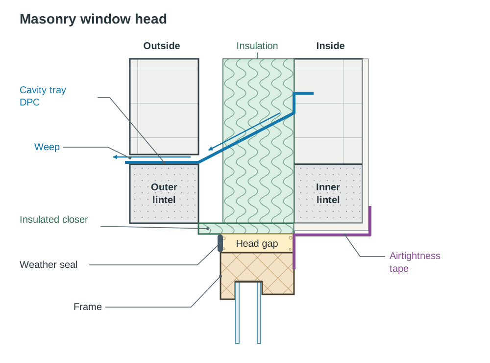
- Structural lintels: Outer leaf carried on a precast concrete or steel lintel; inner leaf carried on a reinforced concrete lintel with a minimum end bearing. The window frame carries no masonry load.
- Stepped cavity tray DPC: Sits above the lintels, sloping upward from outer leaf to inner leaf by at least . Factory-fitted stop ends at both ends prevent water spilling into the reveal.
- Weep holes: Formed by open perpends in the outer leaf immediately above the cavity tray at maximum centres to drain cavity moisture.
- Thermal insulation: Cavity insulation runs down behind the outer lintel. An insulated cavity closer bridges the head to eliminate thermal bridging.
- Frame fixing and head clearance: The frame sits in line with the cavity insulation. It is fixed at the jambs, leaving a compressible expansion gap at the head filled with low-expansion foam so lintel deflection does not crush the frame.
- Airtightness and weather seal: Internal airtightness tape bonds the frame head to the inner block leaf; external low-modulus silicone mastic seals the outer joint behind a drip bead.
Window Cill Detail (Masonry Cavity Wall)
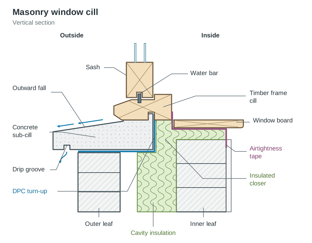
- Precast concrete sub-cill: Cast with an outward fall ( weathering) and an underside throating / drip groove projecting at least clear of the outer masonry leaf.
- Sub-cill DPC: Continuous DPC bedded beneath the sub-cill, turned up at least behind its rear upstand and lapped against the insulated closer.
- Thermal break: Rigid insulation must separate the cold external concrete sub-cill from the warm internal timber window board. Without this break, heat conducts straight out, chilling the reveal and causing surface condensation and mould.
- Frame cill: Timber or uPVC cill profile seated with an anti-capillary groove and a bedded water bar beneath the opening sash.
- Internal window board: Bedded on insulation over the inner leaf blockwork.
- Air seal: Airtightness tape connects the underside of the frame cill to the inner blockwork before the window board and wet plaster are applied.
Window Jamb Detail (Masonry Cavity Wall)
- Cavity closure: The cavity must never be closed with solid blockwork or mortar, as this creates a direct cold bridge and damp route. A proprietary insulated cavity closer with an integral vertical DPC closes the opening.
- Frame alignment: The window frame sits recessed over the insulation layer to maintain continuity with the wall insulation.
- Frame fixings: Galvanised steel frame cramps or proprietary sleeve frame fixings secure the jambs into the inner leaf at approximately vertical centres, placed no closer than from corners.
- Perimeter seals: Low-pressure expanding foam fills the jamb perimeter gap. External silicone mastic seals against the outer brick/block reveal; internal airtightness tape seals the frame to the inner block leaf behind plaster finishes.
Window Detailing in Timber-Frame Walls
In modern timber-frame construction, the detailing changes because the timber stud wall is the primary load-bearing and insulating element, while the outer brick or block leaf functions as a rainscreen cladding.
Build-Up of a Typical Timber-Frame External Wall
From outside to inside:
- brick or render-on-block outer leaf.
- ventilated and drained cavity with stainless steel wall ties.
- Breather membrane vapour-permeable sheet lapped over OSB or plywood structural sheathing.
- treated timber stud frame fully filled with mineral wool or rigid insulation.
- Continuous vapour control layer (VCL) / airtightness membrane.
- uninsulated or insulated timber service battens (forming a service void so wiring and pipes do not puncture the airtightness membrane).
- plasterboard and skim coat.
Timber-Frame Window Opening Sequence
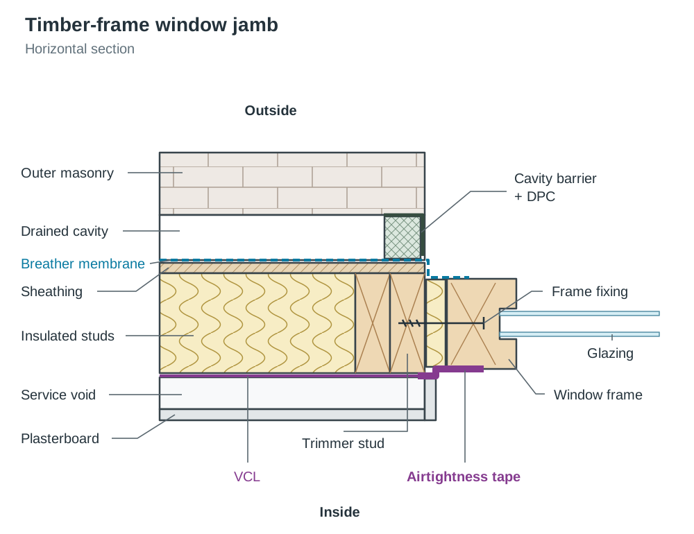
- Structural framing: The opening is framed with doubled jamb studs (king stud and trimmer stud) and a timber lintel sized to transfer floor and roof loads around the aperture. The masonry outer leaf is supported independently on its own lintel.
- Breather membrane reveal dressing: The external breather membrane is cut, folded into the opening reveal, and taped over the sheathing so any cavity moisture is directed outward.
- Cavity barrier and insulated closer: A vertical compressible cavity barrier with an integral DPC is fitted at the jambs to prevent fire spread through the cavity and stop cold bridging.
- Window placement and fixings: The thermally broken window frame is positioned in the plane of the stud insulation. It is fixed through the jambs into the timber trimmer studs using proprietary brackets or direct frame screws, packed level and square.
- Continuous airtightness tape: The internal airtightness membrane is taped directly and continuously onto the timber or alu-clad window frame at the head, jambs, and cill. In marking schemes, this taped seal between the VCL and window frame is the single most heavily credited detail.
- Cill flashing: A flexible cill flashing/DPC runs beneath the frame, turns up at the back by at least , and dresses over the outer leaf sub-cill, incorporating a sub-cill drip.
- Perimeter sealing: Low-expansion insulating foam fills the perimeter gap, protected by an external weather seal and taped internally.
Upgrading and Conserving Traditional Windows
Under the architectural heritage and conservation aims of the syllabus, windows in older vernacular dwellings and protected structures require specific treatment. The governing conservation philosophy is repair rather than replace, following the principle of minimum intervention.
Why Original Windows Are Protected
Original timber sliding sash windows retain historic joinery profiles, cylinder or crown glass with subtle optical distortions, delicate astragal glazing bars, and authentic proportions. Replacing them with modern uPVC units destroys the architectural character of the building, cannot be reversed, and is normally refused planning permission.
Approved Upgrading Methods
- Overhaul and timber repair: Splice new seasoned timber into decayed cills or bottom rails using timber Dutchman repairs; re-cord sashes with heavy-duty braided cords, overhaul pulleys, and balance cast-iron weights so sashes operate smoothly.
- Draught-proofing: Rout discreet brush-pile weather-stripping seals into the staff beads, parting beads, and meeting rails. This is the single most cost-effective upgrade and eliminates up to of perimeter air infiltration without altering the external sightlines.
- Secondary glazing: Install an independent, slim-profile glazed aluminium or timber frame on the internal room reveal, leaving an air gap of between it and the original window. Secondary glazing dramatically improves thermal performance, provides exceptional sound insulation against street noise, and is completely reversible without harming historic fabric.
- Slim-profile double-glazed units: Where existing sash rebates allow and the local conservation officer approves, historic sashes can be fitted with ultra-thin () vacuum or krypton-filled double-glazed units using narrow spacer bars and traditional putty-line profiles.
- Traditional internal shutters and lined curtains: Restoring working timber shutters and fitting heavy lined curtains with pelmets provides substantial nighttime thermal insulation, cutting radiant heat loss to modern performance levels.
Illumination Science: Optics, Vision, and Units of Light
Illumination engineering links human visual biology with the optical physics of light.
The Mechanism of Sight and Visual Acuity
Light passes through the protective, curved cornea, enters the fluid-filled anterior chamber, and passes through the pupil. The iris expands or contracts to control light volume. The flexible crystalline lens adjusts its focal length to focus light onto the retina at the back of the eyeball.
- Rods: Photoreceptors located around the outer retina that function in dim light (scotopic vision). They detect movement and shape but cannot perceive colour.
- Cones: Photoreceptors concentrated at the central fovea that operate in bright light (photopic vision) to resolve fine detail and colour.
- Visual acuity: The ability of the visual system to distinguish fine spatial detail. Acuity increases with higher illuminance, higher contrast between the task and background, longer viewing time, and younger observer age.
- Dark adaptation: Moving from bright daylight into a dim room requires time for rods to regenerate photopigments. High brightness contrasts inside a space cause constant, fatiguing adaptation cycles.
Optical Principles: Reflection and Refraction
- Reflection: When light strikes a surface, the angle of incidence equals the angle of reflection (), measured from the normal. Smooth polished surfaces cause specular reflection (mirror reflections and harsh glare). Rough, matt surfaces produce diffuse reflection, scattering rays in all directions. A white matt ceiling with an reflection factor scatters natural daylight downward uniformly across the room.
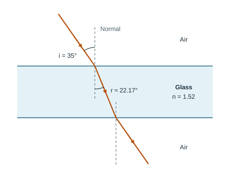
- Refraction: When light passes from one transparent medium into another of different optical density, its velocity changes, causing the ray to bend. Refraction is governed by Snell's Law:
Where is the refractive index (for standard glass, ). Light entering glass from air bends towards the normal; on emerging back into air, it bends away from the normal.
Worked Refraction Example: A ray of light in air strikes a glass pane at an incident angle of . Taking the refractive index of glass as , find the angle of refraction ():
Photometric Quantities and Units
| Quantity | Symbol | Unit | Physical Meaning |
|---|---|---|---|
| Luminous flux | or | Lumen (lm) | Total volume of visible light emitted by a light source in all directions per second. |
| Luminous intensity | Candela (cd) | Light power emitted by a point source in a given direction per unit solid angle. | |
| Illuminance | Lux (lx) | Density of luminous flux arriving on a surface (). Calculated as . | |
| Luminance | Candela per square metre (cd/m²) | The perceived brightness of a luminous or reflecting surface seen by the eye. |
Inverse Square Law: For a point light source illuminating a surface perpendicular to the beam:
If a lamp with luminous intensity hangs directly above a desk, the illuminance is:
If the lamp is raised to ( doubled):
Doubling the distance reduces illuminance to one quarter (). Where the light hits at an angle to the normal, the cosine law applies ().
Daylighting: CIE Overcast Sky, Daylight Factor, and Calculations
The CIE Standard Overcast Sky
Because natural sky brightness changes from minute to minute, international building calculations rely on the Commission Internationale de l'Éclairage (CIE Standard Overcast Sky). In this model, the sky is assumed to be equally bright in every compass direction, so orientation does not enter the calculation. The sky is non-uniform vertically: it is three times brighter at the zenith (directly overhead) than down at the horizon. For Ireland, the standard outdoor illuminance on an unobstructed horizontal roof plane is taken as .
The Daylight Factor ()
The daylight factor expresses indoor illuminance on the working plane as a percentage of simultaneous unobstructed outdoor illuminance:
Because is a ratio, its value stays constant whether the day is bright or dull.
The Three Components ():
- Sky Component (SC): Light received directly through the window from the visible sky patch.
- Externally Reflected Component (ERC): Light reaching the point after bouncing off opposing buildings or ground paving.
- Internally Reflected Component (IRC): Light reaching the point after multiple inter-reflections off interior walls, ceilings, and floors.
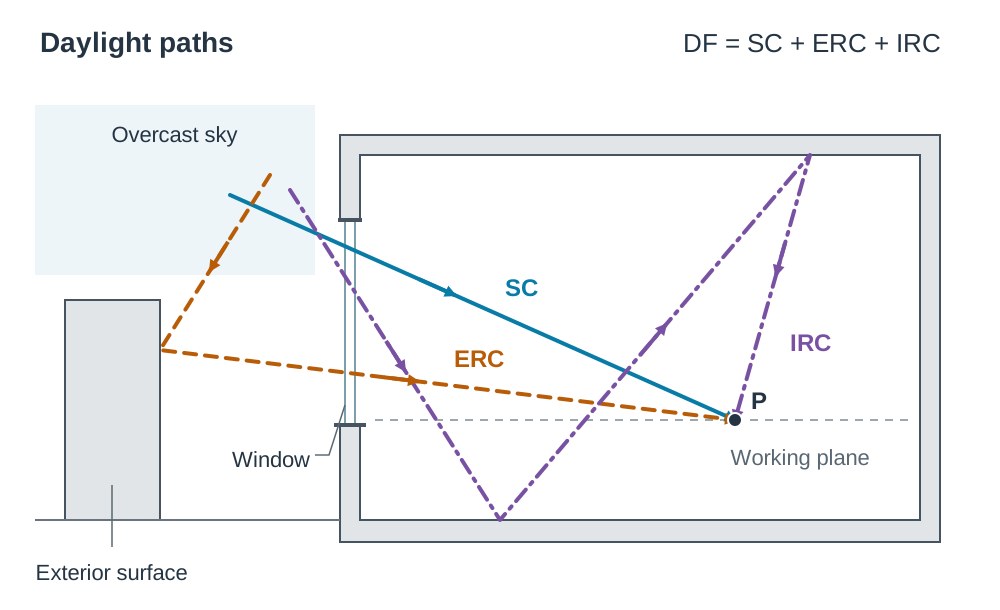
Daylight penetration rule: Useful daylight penetrates a side-lit room to a horizontal depth equal to twice the window head height above floor level ().
Recommended average daylight factors: Kitchens ; living rooms ; bedrooms .
Degree of Efficiency Method
This formula estimates the approximate average daylight illuminance across a room's working plane under the CIE overcast sky:
Where:
- = Average internal illuminance (lux)
- = External horizontal illuminance from CIE standard overcast sky ()
- = Window Factor, accounting for a vertical window seeing only half () of the total sky hemisphere ()
- = Degree of efficiency coefficient, accounting for dirt, glazing bars, and glass transmittance (typically , but always use the value stated in your exam question)
- = Net window glazed area ()
- = Total floor area of the room ()
Suggested Experiment: Measuring Daylight Factor Across a Room
(Part of the syllabus list of suggested investigations and a model response when asked to describe a lighting test.)
- Aim: To measure how the daylight factor varies with distance from a window under an overcast sky.
- Apparatus: Two calibrated digital lux meters, measuring tape, recording sheet, and graph paper.
- Method:
- Perform the test on a uniformly overcast day (no direct sunbeams entering the room).
- Mark measurement points along the room centre-line at intervals from the window wall to the back wall at working plane height ().
- Position one lux meter outdoors on an unobstructed horizontal surface to read simultaneous outdoor illuminance ().
- Read the internal illuminance () at each marked point, ensuring the observer's body does not cast a shadow on the sensor.
- Take three simultaneous sets of paired readings and average them.
- Calculate at each station and plot against distance from the window.
- Conclusion: Daylight factor drops off sharply with distance, falling below beyond twice the window head height (). Light-coloured walls raise readings at the rear of the room by boosting the internally reflected component (IRC).
Glare Control, Solar Shading, and Quality of Illumination
Glare Phenomena and the Glare Index
Glare is visual discomfort or reduced visibility caused by excessive brightness or extreme luminance contrast in the field of view:
- Disability glare: Direct light scatter within the eyeball that physically reduces contrast on the retina, blinding the viewer (such as oncoming high-beam headlights or low-angle winter sun reflecting off a computer screen).
- Discomfort glare: High luminance contrast that causes psychological irritation, visual fatigue, and headaches without physically blinding the observer (such as an unshaded, brilliant window surrounded by dark, unpainted reveal walls).
The Glare Index Scale:
- : Glare is just perceptible.
- : Glare is acceptable for domestic living rooms and general offices.
- : Glare becomes uncomfortable and induces eye strain.
- : Glare is intolerable.
Architectural Glare and Solar Controls
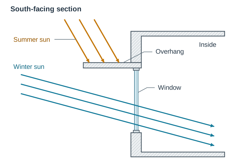
- Brise-soleil and structural overhangs: External horizontal louvres or roof overhangs mounted on south elevations. They block high-altitude summer sun (around noon elevation in Ireland) to stop glare and overheating, while allowing low-altitude winter sun () to pass underneath for passive solar heating. This directly aligns with passive house shading principles.
- Light shelves: Horizontal reflective shelves dividing upper daylight glazing from lower view glazing. The shelf shades the lower glass while bouncing direct sunlight up onto a white ceiling, throwing diffuse light deep into the room.
- Splayed reveals: Tapered window jambs painted white soften the harsh visual contrast between outdoor sky luminance and the darker interior wall.
- Internal blinds: Venetian or roller blinds provide manual glare control for occupants.
Conditions for Good Illumination
- Adequate illuminance: Meeting task benchmarks ( for living areas, for kitchens and study desks, for technical drawing).
- Reasonable uniformity: Avoiding sharp drops in illuminance across the working plane.
- Glare limitation: Shielding light fittings and shading windows with high luminance.
- Balanced contrast: Controlling luminance ratios between the task, its immediate surround, and the wider room.
- Good colour rendering: Using light sources with a broad colour spectrum so materials appear natural.
- Directionality and modelling: Arranging light to reveal three-dimensional form with soft shadows while preventing harsh shadows over the task plane.
- Absence of flicker: Using high-frequency solid-state LED fittings to prevent stroboscopic effects and visual fatigue.
Key terms
- Cavity tray DPC
- A flexible damp-proof barrier installed above openings, stepping upward by at least 150 mm from outer to inner leaf, fitted with stop ends to shed cavity water through weep holes.
- Insulated cavity closer
- A rigid insulated profile fitted with a vertical DPC used to close a wall cavity at reveals without creating a thermal bridge or moisture path.
- Thermal break
- An insulating material of low thermal conductivity built into an aluminium frame profile or between a cold sub-cill and warm internal window board to stop conductive heat loss.
- Water bar
- A metal or durable hardwood strip bedded in a groove in a timber cill to prevent wind-driven rainwater blowing underneath an opening sash.
- Capillary groove
- A machined groove in a sash or frame edge that widens the joint gap beyond the capillary threshold, preventing water being drawn inward by surface tension.
- Haunched mortise and tenon
- A corner joinery joint where a shortened haunch fills the frame rebate groove while the tenon provides structural resistance against sash racking.
- Low-E coating
- A microscopically thin metallic oxide coating applied to glass that admits short-wave solar radiation while reflecting long-wave room heat back inside.
- Warm-edge spacer
- An insulating composite or stainless-steel spacer bar separating glass panes that reduces edge heat loss and stops perimeter condensation.
- U-value
- Thermal transmittance measuring the rate of heat transfer through one square metre of a building element per degree Kelvin temperature difference (W/m²K).
- g-value
- The solar factor measuring the fraction of total incident solar radiation that passes through a glazing unit into an interior space (expressed as a decimal).
- Purge ventilation
- Rapid, manually controlled ventilation through openable window sashes (at least 1/20th of room floor area) to exhaust moisture, smoke, or pollutants.
- Background ventilation
- Continuous, controllable passive ventilation through trickle vents or wall vents to maintain basic indoor air quality without draughts.
- CIE standard overcast sky
- An international reference overcast sky model that is three times brighter at the zenith than at the horizon, delivering 5000 lux horizontally in Ireland.
- Daylight factor
- The ratio of internal horizontal illuminance on the working plane to simultaneous unobstructed outdoor illuminance under a CIE overcast sky, expressed as a percentage.
- Sky component (SC)
- The portion of the daylight factor received directly from the visible sky patch through a window opening.
- Internally reflected component (IRC)
- The portion of the daylight factor reaching an indoor point after inter-reflecting off interior walls, ceilings, and floors.
- Glare index
- A numerical scale assessing visual discomfort from brightness contrast, ranging from 10 (just perceptible) to 28 (intolerable).
- Brise-soleil
- An external architectural solar shading screen of horizontal or angled louvres designed to intercept high-altitude summer sun while admitting diffuse daylight.
Check yourself
What is the standard design illuminance benchmark for a CIE standard overcast sky in daylight calculations?
5000 lux on an unobstructed horizontal surface.
A living room measures 4.5 m × 4.0 m. Using the degree of efficiency method with Lo = 5000 lux, WF = 0.5, and E = 0.4, what average illuminance is produced by a net glazed window area of 2.7 m²?
Floor area = 4.5 × 4.0 = 18.0 m². Li = 5000 × 0.5 × 0.4 × (2.7 / 18.0) = 1000 × 0.15 = 150 lux (which matches the recommended 150 lux benchmark for living areas).
What are the four mandatory criteria for an emergency escape window under TGD Part B?
Minimum clear openable width of 450 mm, minimum clear height of 450 mm, minimum clear openable area of 0.33 m², and opening cill level not more than 1100 mm above finished floor level.
Name the three components that make up the total Daylight Factor (DF).
Sky Component (SC), Externally Reflected Component (ERC), and Internally Reflected Component (IRC).
Why is an anti-capillary groove machined into the underside of an opening sash or cill?
It widens the joint gap beyond the capillary threshold, breaking surface tension so rainwater cannot be drawn inward between the frame and sash.
What is the difference between disability glare and discomfort glare?
Disability glare physically scatters light inside the eye and reduces retinal contrast, impairing vision; discomfort glare causes visual fatigue and irritation from high brightness contrast without necessarily blinding the viewer.