
Walls form the primary vertical envelope and spatial divisions of a domestic building. At Leaving Certificate Higher Level, walls must be analysed structurally (load-bearing versus non-load-bearing, slenderness ratio, and bonding), environmentally (moisture exclusion, airtightness, and vapour dynamics), and thermally (U-value calculations, thermal bridging, and Part L compliance). Students must also master the technical scale drafting (typically 1:5 or 1:10) of critical envelope junctions for the compulsory 120-mark Question 1, evaluate retrofit strategies for existing walls, and specify construction build-ups for fire resistance and acoustic isolation.
1. Functional Requirements, Structural Classification, and Material Selection
Every external and internal wall in a domestic dwelling must satisfy clear structural and environmental standards governed by the Building Regulations:
- Structural Strength and Stability: The wall must carry its own dead load and all imposed loads (floors, roofs, occupants, and lateral wind pressures) safely down to the substructure without crushing, bowing, or buckling. The slenderness ratio compares a wall's effective height or length to its effective thickness. A tall, thin wall buckles much more easily under vertical weight and wind, so it must be stiffened with attached piers or intersecting cross walls.
- Weather and Moisture Resistance: External walls must resist driving rain, snow, and rising groundwater to maintain a completely dry interior.
- Thermal Performance and Airtightness: The building envelope must limit heat transmission and air leakage while eliminating thermal bridges and surface condensation.
- Fire Safety: Internal and separating walls must resist structural collapse, smoke penetration, and flame spread for a specified rating (typically 30 minutes for domestic partitions and 60 minutes for party walls).
- Acoustic Insulation: Walls must reduce the passage of airborne and impact sound between rooms and adjoining dwellings.
Structural Classification and Universal Design
- Load-bearing walls carry weight from upper floors, ceiling joists, or roof trusses down to dedicated strip foundations or engineered beams. Removing or altering a load-bearing wall without temporary props and an engineered replacement beam will cause structural collapse.
- Non-load-bearing partitions carry only their own self-weight and divide interior room layouts. Using non-load-bearing partitions provides flexibility: they permit open-plan living (improving natural daylight and social interaction, though increasing sound transfer and heating demand) and support Universal Design. In universal design, internal partitions can incorporate 'soft spots' for future through-floor home lifts, accommodate 800 mm to 900 mm clear opening doorways for wheelchair access, and include plywood pattressing behind plasterboard in bathrooms and corridors for the secure retrofitting of grab rails.
Choosing Materials for an External Wall
When asked in the examination to recommend or justify an external wall material, evaluate these factors:
- Structural strength: A solid 7.5 N/mm² concrete block inner leaf easily carries domestic joists and roof trusses, whereas lightweight aerated blocks require verification of compressive strength.
- Durability and weather resistance: External units must withstand driving rain, frost attack, and sulphate attack. Frost-resistant masonry units are essential for parapets, cills, and below-DPC rising walls where saturation occurs.
- Thermal performance: Materials with low thermal conductivity () reduce conductive heat loss. Aerated blocks () insulate far better than standard dense concrete blocks ().
- Fire resistance: Masonry is inherently non-combustible; timber-frame structures achieve required fire resistance through protective gypsum plasterboard linings and internal cavity barriers.
- Cost, availability, and buildability: Concrete blocks are inexpensive, widely available across Ireland, and rely on standard trade skills. Timber-frame panels are factory-manufactured and erected on site within days, closing in the envelope rapidly. Natural stone and facing brick require specialised craft skills and carry higher material costs.
- Sustainability and context: Timber sequesters carbon during growth and embodies low energy; locally produced concrete blocks reduce transport emissions. The external finish should harmonise with the local vernacular, such as wet-dash render in exposed western rural landscapes.
2. External Masonry Cavity Walls and Moisture Control
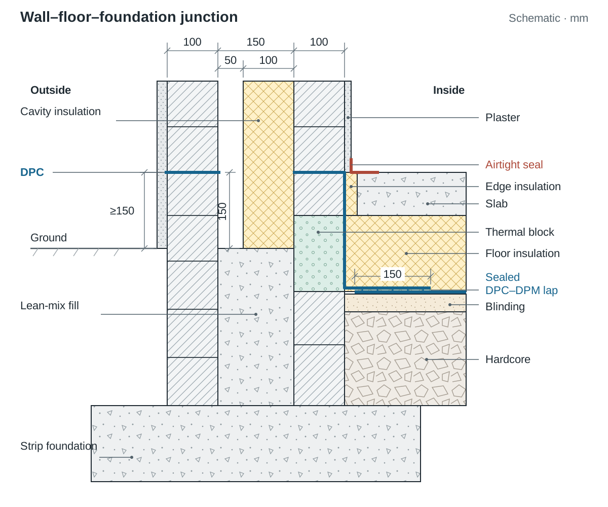
The masonry cavity wall is the traditional external envelope in Irish construction. Throughout these notes and in standard Question 1 drawings, the standard specification comprises a 100 mm outer leaf, a 150 mm cavity (100 mm rigid insulation plus a 50 mm clear residual cavity), and a 100 mm load-bearing inner leaf.
- Outer Leaf (100 mm): Concrete blockwork with external sand-cement render, or facing brickwork. It absorbs the impact of driving rain and sheds bulk surface runoff.
- Cavity (150 mm total): With partial fill, rigid boards (such as 100 mm polyisocyanurate, or PIR) are held tight against the inner leaf using retaining clips on wall ties, leaving a clear residual cavity of at least 40 to 50 mm behind the outer leaf. This void provides a complete physical break that stops capillary water transfer. Mortar droppings must be kept out using cavity bats during construction. With a full-fill system, the cavity contains no residual void; rain resistance relies entirely on certified water-repellent insulation (such as pumped expanded polystyrene bonded beads or silicone-treated mineral wool) installed by an approved contractor.
- Inner Leaf (100 mm): Dense concrete blocks laid in stretcher bond to carry floor and roof loads.
Wall Ties and Rising Walls
Leaves are tied together using austenitic stainless steel wall ties embedded at least 50 mm into each mortar bed. Ties are spaced at a maximum of 900 mm centres horizontally and 450 mm centres vertically (staggered, yielding approximately 2.5 ties per square metre). Around window and door openings, vertical spacing tightens to a maximum of 300 mm centres within 225 mm of the reveal. Each tie incorporates a downward-pointing central drip crimp to force tracked rainwater to drop harmlessly into the cavity void. Below ground, masonry from the concrete strip foundation to ground level forms the rising wall. The cavity is filled with lean-mix concrete up to at least 150 mm below the DPC to resist lateral soil backfill pressure and prevent water ponding at the base of the cavity.
Damp-Proof Courses and Stepped Cavity Trays
- Damp-Proof Course (DPC): An impervious bituminous or heavy polyethylene barrier bedded in mortar at least 150 mm above finished external ground level to stop rising damp via capillary action. At the floor junction, the inner-leaf DPC must lap and be sealed to the subfloor Damp-Proof Membrane (DPM) or radon barrier by at least 150 mm, maintaining an unbroken moisture and gas barrier.
- Stepped Cavity Trays: Water running down the inside face of an outer leaf must be intercepted above openings and roof abutments. A flexible cavity tray slopes downward across the cavity, bedded with an upstand of at least 150 mm into the inner leaf, and steps out over the lintel. It includes 75 mm stop ends at each end to stop water spilling into the reveal. Open perpends or plastic vents act as weep holes, positioned directly above the tray at maximum 900 mm centres (minimum two per opening) to discharge water externally.
3. Openings, Lintels, Arches, and Parapets
Openings interrupt the continuous load path of a wall and require lintels or arches to bridge weight across to flanking jambs.
Lintels
A lintel is a horizontal structural beam spanning an opening. In cavity construction:
- Inner Leaf: Carries floor and roof loads using a precast prestressed concrete lintel, or a reinforced concrete lintel. It requires a minimum end bearing of 150 mm onto solid blockwork.
- Outer Leaf: Supported by an independent precast concrete lintel, a pressed galvanised steel angle, or a masonry arch.
- Thermal Continuity: A combined insulated steel lintel or an insulated cavity closer between separate lintels prevents direct thermal bridging over the opening.
Masonry Arches
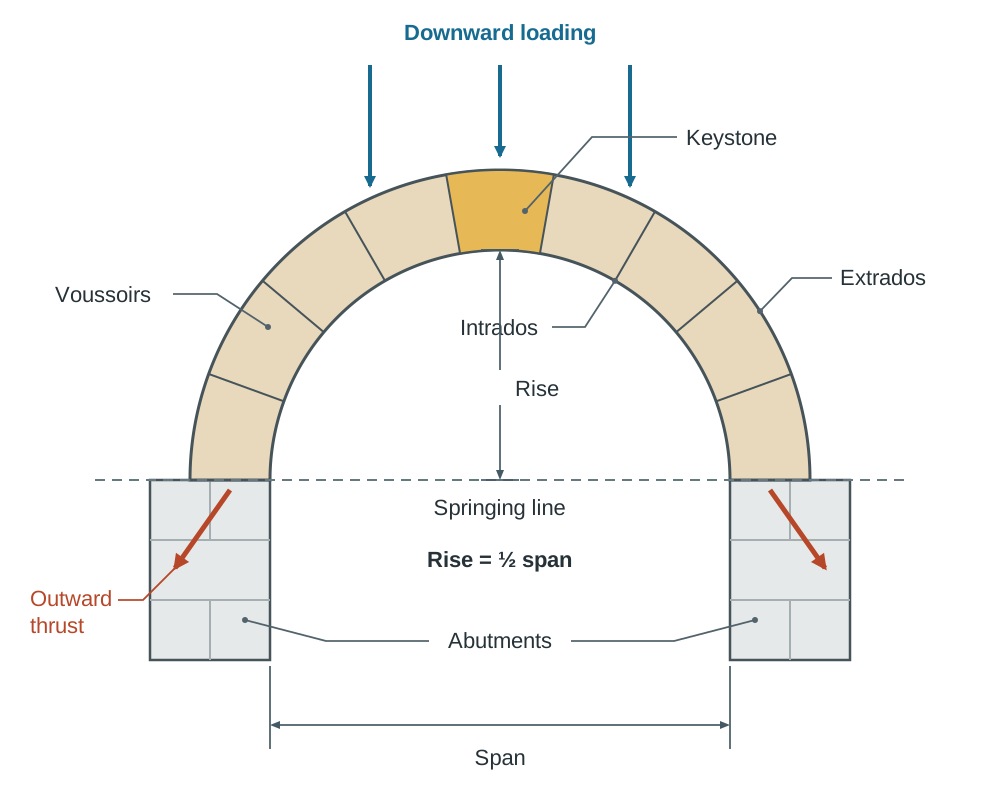
An arch transfers overhead structural loads down to abutments entirely through compression:
- Wedge-shaped masonry units called voussoirs radiate from a central focal point.
- The central wedge at the apex is the keystone, inserted last to lock the arch into compression.
- The line where the arch begins curving from the vertical support is the springing line; the horizontal distance between supports is the span, and the vertical height to the crown is the rise.
- The inner curved surface is the intrados; the outer curved boundary is the extrados.
- Under vertical gravity loads, an arch generates outward lateral thrust at its supports. The supporting abutments (piers or flank walls) must possess sufficient mass and width to prevent spreading.
- During construction, arches are built over a temporary timber framework called centring, which supports the masonry until the keystone and mortar joints have cured.
- Arch Types: A semicircular arch has a rise equal to half its span; a segmental arch is struck from a centre below the springing line, creating a flatter curve common over domestic openings; a flat (soldier) arch consists of bricks laid vertically on end and requires a steel or concrete lintel behind it to support structural weight; a relieving arch is built into the wall above a flat opening to divert overhead loads past the lintel; a rough arch uses standard uncut bricks with wedge-shaped mortar joints, whereas a gauged arch uses purpose-cut voussoirs with fine, uniform joints.
Window Cills and Jamb Details
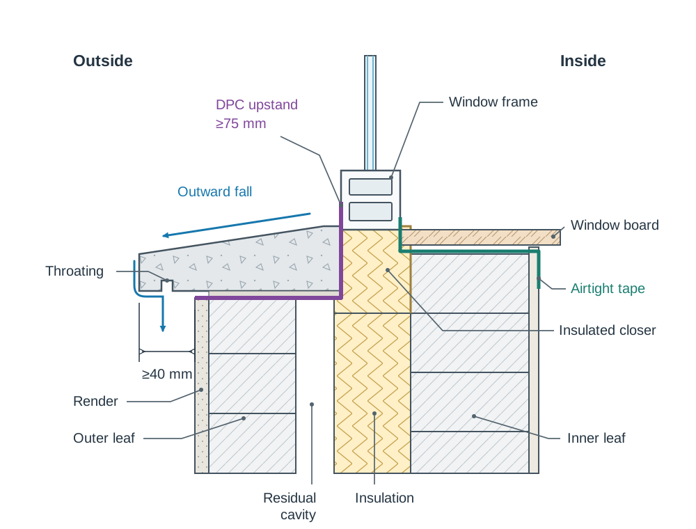
- Cills: External precast concrete cills must have an outward fall to shed rainwater, extend at least 40 mm clear of the finished render, and feature an undercut throating (drip groove) on the underside. The throating stops water tracking back across the joint to the wall face. A continuous cill DPC must sit beneath the cill, turned up at least 75 mm at the back and ends.
- Jamb Closers: An insulated cavity closer with an integral vertical DPC seals the cavity reveal, carrying insulation right up to the window frame and eliminating the cold bridge.
Parapets: Coping versus Capping
A parapet extends an external wall above the roof plane. Because it is exposed to weather on both faces and top, it demands robust moisture detailing:
- A coping projects beyond both faces of the wall and features an undercut throating on each underside overhang, throwing rainwater clear of the wall faces.
- A capping finishes flush with the wall faces and does not throw water clear, making it more vulnerable to rain penetration.
- Both assemblies require a continuous DPC bedded in mortar directly beneath the coping units, frost-resistant blockwork, and a stepped cavity tray linked directly into the roof flashing.
4. Timber-Frame External Walls and Airtightness
In timber-frame construction, an engineered timber cage carries structural loads, shielded externally by a drained rainscreen cladding.
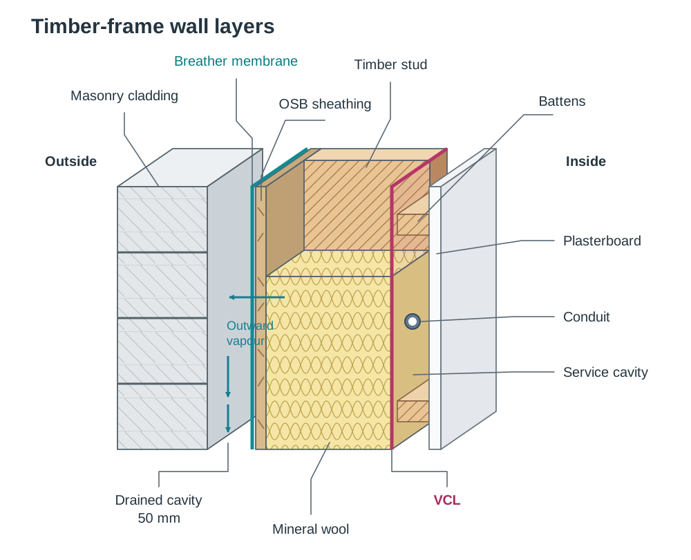
Construction Build-Up (Outside to Inside)
- External Cladding: 100 mm rendered concrete blockwork or brickwork to repel bulk weather.
- Drained Cavity (50 mm): Drains any driving rain that penetrates the outer leaf; tied to timber studs using flexible stainless steel timber-frame ties.
- Breather Membrane: A vapour-permeable, water-resistant sheet fixed over sheathing. It keeps liquid water and wind out while allowing moisture vapour within the frame to migrate outward.
- Structural Sheathing (9–12 mm OSB or Plywood): Nailed to timber studs to provide racking resistance against horizontal wind loads.
- Structural Timber Framing (140 × 44 mm): Vertical studs at 400 mm centres, packed completely with non-combustible mineral wool insulation.
- Vapour Control Layer (VCL): Heavy-duty reinforced polyethylene sheet or sealed membrane fitted on the warm room side of the framing to prevent warm, moisture-laden indoor air from entering the cold stud void.
- Service Cavity (25–38 mm): Created using horizontal treated timber battens, allowing electrical conduits and pipework to run without puncturing the airtight VCL.
- Internal Lining: 12.5 mm plasterboard, taped, jointed, and skimmed to provide domestic fire resistance.
Airtightness Principles and Testing
Airtightness eliminates accidental air leakage through cracks, gaps, and junctions in the external envelope. Uncontrolled air infiltration wastes heat, causes draughts, and introduces interstitial condensation into structural cavities. Airtight construction must follow the rule: build tight, ventilate right, pairing high airtightness with controlled ventilation (such as Mechanical Ventilation with Heat Recovery, or MVHR).
- Masonry walls: The continuous internal wet plaster coat forms the primary airtightness barrier. Plaster must extend down behind skirting boards to the floor slab and be sealed to the floor using proprietary airtightness tape or a wet parging coat.
- Timber frame: The taped and sealed VCL forms the primary air barrier, protected by the internal service batten space.
- Critical junctions: Sealing must be continuous at wall-to-floor junctions, wall-to-roof junctions, window/door frame reveals, and around service pipe penetrations using specialised flexible grommets and tapes.
- Testing: Airtightness is measured on site using a blower door pressurisation test. A variable fan installed in an external doorway pressurises and depressurises the sealed building to 50 Pascals (Pa). The leakage rate is expressed as air permeability in at 50 Pa. Under Part L of the Building Regulations, the backstop limit for new dwellings is 5.0 m³/(h·m²) at 50 Pa, while low-energy NZEB homes typically achieve between 1.0 and 2.0 m³/(h·m²).
5. Internal Walls, Partitions, and Acoustic Detailing
Internal walls divide living spaces, support upper structures, isolate sound, and provide fire compartmentation.
Internal Masonry Walls and Junctions
Load-bearing internal block walls (100 mm solid concrete blocks) require dedicated strip foundations or reinforced floor slab downstands. Overhead timber floor joists bear onto a horizontal treated timber wall plate () to distribute loads evenly. Tying an internal wall to an external wall is achieved in two ways:
- Block bonding (toothing): Every second course of the internal wall is toothed directly into the inner leaf of the external wall. While structurally strong, it is labour-intensive and can introduce thermal bridging if the partition is dense concrete blockwork.
- Proprietary metal connectors: A vertical stainless steel channel is mechanically plugged to the inner leaf, and flat stainless steel ties slide into the channel and bed into the mortar joints of the partition at 450 mm vertical centres. Scrim tape is placed over the plaster junction to prevent shrinkage cracks.
Internal Timber Stud Partitions
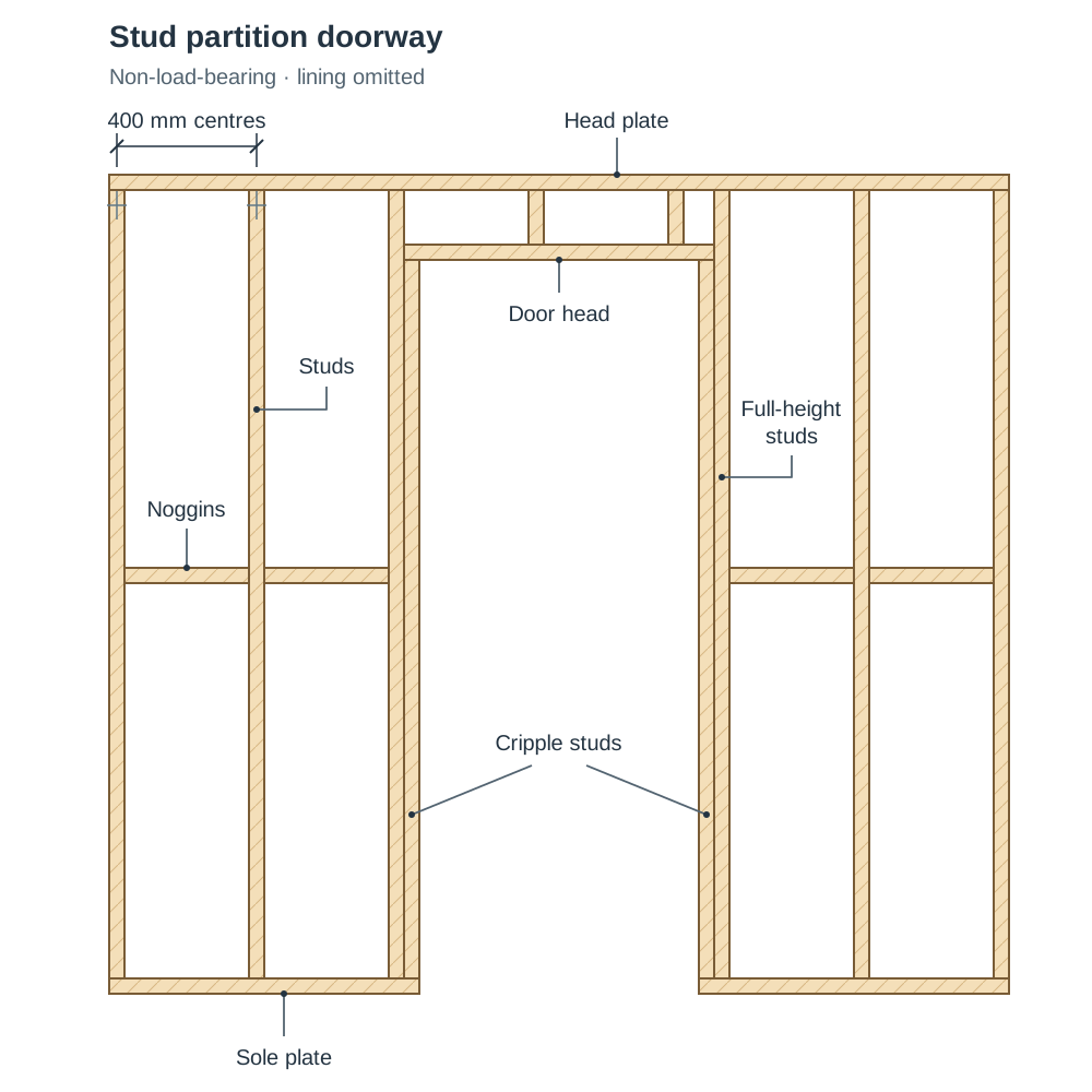
A lightweight timber partition consists of a horizontal timber sole plate () anchored to the floor (over a DPC strip on concrete floors), vertical studs spaced at 400 mm centres, and a horizontal head plate secured to overhead ceiling joists. Horizontal noggins are fitted tightly between studs at mid-height to prevent timber twisting and provide fixing support for heavy wall fittings. Around door openings, a horizontal timber head is carried on vertical cripple studs, flanked by full-height studs.
Service Installation Rules
- Blockwork walls: Vertical chases for electrical conduits must not exceed one-third of the block thickness. Horizontal chases cut across compressive stress lines; they must not exceed one-sixth of the block thickness and should be avoided entirely in load-bearing masonry.
- Timber studs: Drill holes strictly on the vertical centreline (neutral axis) of the stud so that plasterboard screws cannot pierce conduits. Keep holes as small as possible and never notch studs that form part of a door opening. Best practice is running services inside a dedicated service cavity.
Acoustic Isolation and Fire Resistance
To achieve a 30-minute fire rating and high acoustic reduction in a stud partition:
- Frame with timber studs at 400 mm centres on sole and head plates.
- Friction-fit 100 mm acoustic mineral wool quilt inside the stud void to absorb airborne acoustic energy.
- Install two layers of 12.5 mm plasterboard on each side, staggering joints between layers. Plasterboard contains chemically bound water that vaporises slowly when heated, preventing flame spread. Staggered dual layers add structural mass.
- Mount plasterboard on one side onto horizontal resilient bars (metal decoupling channels) fixed across the studs to break direct mechanical vibration transfer.
- Apply acoustic mastic around the entire perimeter of the lining boards.
- Party (Separating) Walls: Must achieve at least 60 minutes of fire resistance. They are built using 215 mm dense concrete blockwork laid on flat and plastered on both faces, or twin 100 mm block leaves separated by a clear 50 mm cavity. Masonry party walls must extend tightly to the underside of the roof covering and be fire-stopped with mineral wool mortar capping. Floor joists must never be built into a party wall; they must be hung from masonry-mounted joist hangers to maintain fire integrity and eliminate flanking transmission.
- The Mass Law: For airborne sound, doubling the mass per unit area of a solid wall increases its acoustic insulation by roughly 5 dB.
6. Wall Finishes: Rendering, Plastering, and Masonry Bonds
Finishes protect masonry substrates from rain, prevent air leakage, and supply decorative surfaces.
External Rendering: Three-Coat System
External rendering provides weather exclusion over blockwork. The total combined thickness must not exceed 20 mm:
- Scud Coat (3–5 mm): A wet, slurry mix ( cement:sharp sand) thrown on vigorously with a trowel or brush onto dampened blockwork, so that it clings in a rough, open texture to create a mechanical key.
- Scratch Coat (10–12 mm): A cement:lime:sand mix trowelled on, ruled flat, and combed in horizontal wavy lines before curing.
- Finish Coat (5–6 mm): A weaker or equal mix ( cement:lime:sand). Structural Rule: The finish coat must never be stronger than its backing coat; otherwise, differential drying shrinkage stresses will cause crazing, cracking, and debonding. Textures include smooth wood-float, wet-dash (roughcast aggregate premixed into wet slurry and thrown onto the wall), and dry-dash (dry stone chippings cast onto a fresh, soft receiving coat).
Internal Finishes: Wet Plaster versus Dry Lining
- Wet Plastering: Traditional two-coat gypsum applied to masonry. A 9–11 mm gypsum bonding undercoat is applied first and scratched, followed by a 2–3 mm smooth gypsum skim coat. Wet plastering seals microscopic blockwork joints, serving as an effective airtightness barrier.
- Dry Lining: Fixing 12.5 mm plasterboards using gypsum adhesive dabs (dot-and-dab) directly to blockwork, or screwing boards to treated vertical timber battens. Dry lining permits fast installation and creates a space for insulation and pipework without chasing masonry.
- Painting: Plaster and render must dry completely before painting (up to six weeks for heavy render). Painting over damp surfaces traps moisture, causing blistering, flaking, and efflorescence.
Masonry Bonds
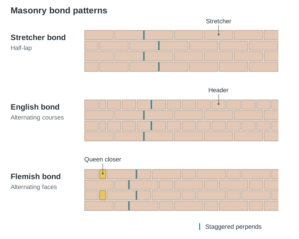
A bond is the regular pattern in which masonry units are laid, overlapping vertical joints (perpends) to distribute concentrated loads evenly across the wall. The minimum overlap is one-quarter of a brick length (56 mm):
- Stretcher Bond: Blocks or bricks are laid showing only their long faces (stretchers), overlapping by half a unit in every course. Standard for 100 mm block leaves and cavity walls.
- English Bond: Alternating courses of headers (short ends) and stretchers. It is exceptionally strong and used for thick solid walls.
- Flemish Bond: Alternating headers and stretchers within every single course, creating an attractive decorative brick façade common in period and conservation work. Requires cut bricks (queen closers) next to corner units to maintain the bond.
7. Upgrading Existing Walls: Retrofit and Breathability
Upgrading the thermal performance of existing external walls is a recurring exam topic. Three main methods exist:
1. External Wall Insulation (EWI)
Rigid insulation boards (100–150 mm expanded polystyrene or mineral wool) are mechanically anchored and adhesive-bonded to the exterior masonry face, covered by a glass-fibre reinforcing mesh and a thin-coat silicone or acrylic render.
- Advantages: Thermal insulation is continuous, completely eliminating thermal bridges at intermediate floor joists and internal cross walls; preserves internal room floor space; causes zero internal living disruption; preserves the thermal mass of existing masonry inside the warm envelope.
- Disadvantages: Highest capital cost; alters the architectural exterior appearance (unsuitable for protected structures or historic brick); requires extending window cills, roof eaves, downpipes, and door thresholds; may require planning permission.
2. Internal Wall Insulation (Dry Lining)
Insulated plasterboard composite panels (rigid PIR bonded to plasterboard) or timber/metal stud systems packed with mineral wool are fixed to internal wall faces with a continuous vapour control layer on the warm side.
- Advantages: Lower capital cost; can be carried out room by room; interior rooms heat up very quickly because masonry thermal mass is outside the heated space.
- Disadvantages: Reduces usable internal floor area; requires relocating radiators, light switches, electrical sockets, skirting boards, and window reveals; leaves major thermal bridges at intermediate timber floor junctions and internal partition connections where mould can form.
3. Pumped Cavity Fill
Bonded expanded polystyrene (EPS) beads mixed with an adhesive binder, or water-repellent mineral wool fibres, are injected through holes drilled in mortar perpends across the outer leaf.
- Advantages: Lowest installation cost; fast application with no disruption to indoor floor area or external aesthetics.
- Disadvantages: Can only be used in clear, clean, unfilled cavities; mortar snots bridging the cavity can create voids or track driving rain across to the inner leaf; achieves lower overall U-value reduction than comprehensive EWI due to cavity width limits.
Solid Walls and Breathability
Traditional buildings built before the mid-twentieth century feature solid walls of rubble stone or solid brick laid in lime mortar (typically 450 to 600 mm thick). These walls are vapour-permeable (breathable): they absorb moisture and release it outward through evaporation. Applying impermeable Portland cement render, waterproof paints, or foil-backed PIR internally traps moisture inside the wall core. This trapped damp rots embedded timber joist ends and causes frost spalling. Solid traditional walls must be upgraded using breathable materials: internal hemp-lime plaster or wood-fibre insulation boards finished with breathable lime plaster.
8. Building Physics: U-Values, Condensation, and Thermal Bridging
Thermal Transmittance (U-Value)
The rate of heat transfer through a composite wall is its U-value (measured in ). The lower the U-value, the better the wall insulates.
Where is thickness in metres, (or ) is thermal conductivity in , is external surface resistance, is internal surface resistance, and is cavity air space resistance.
Part L Statutory Standards
Under Technical Guidance Document L (TGD Part L) of the Irish Building Regulations, maximum permitted elemental (backstop) U-values are established:
- New Dwellings: External walls must not exceed a maximum U-value of 0.18 W/m²K.
- Existing Buildings (Major Renovation): When an existing dwelling undergoes major renovation (affecting more than 25% of the building envelope's surface area), renovated external walls must achieve a U-value of approximately 0.35 W/m²K for cavity walls or 0.55 W/m²K for solid walls, while satisfying overall dwelling primary energy and carbon metrics.
Thermal Bridging
A thermal bridge is a localized area of high thermal conductivity in the envelope (such as uninsulated lintels, window reveals, or wall-to-floor junctions). Heat bypasses the insulation, creating cold indoor surface temperatures. When internal surface temperatures drop below the dew point, airborne moisture condenses, supporting toxic mould growth. Thermal bridging is prevented by:
- Maintaining unbroken insulation alignment across all junctions.
- Using insulated cavity closers at window and door reveals.
- Laying high-strength, low-density aerated (aircrete) thermal blocks (, compared to for dense concrete) at the base course of the inner leaf to bridge between wall and floor insulation.
Surface versus Interstitial Condensation
- Surface condensation forms on visible internal surfaces when warm, moist air contacts a cold wall surface below the dew point. It is remedied by adding insulation to raise surface temperatures and providing adequate extract ventilation.
- Interstitial condensation occurs inside the structural core of the wall, where water vapour diffuses through the structure until it reaches a cold layer below its dew point. It causes rot in timber framing and wets insulation, ruining its thermal performance.
- Design Rule: Keep the wall tight inside, open outside. Position the vapour control layer (VCL) on the warm room side of the insulation, and install a breather membrane on the cold external side. This prevents internal moisture entering the cold wall core while allowing any trapped moisture to escape safely outwards.
Internal Walls as Thermal Mass
Thermal mass describes the capacity of heavyweight building materials to absorb, store, and slowly release heat. In passive solar design, solar gain entering south-facing glazing is absorbed during the day by internal dense concrete block walls (finished with wet plaster, not insulated dry lining). This moderates daytime peak temperatures, preventing overheating, and radiates stored heat back into rooms at night as temperatures drop.
9. Technical Scale Drawing: Checklists and Conventions
Compulsory Question 1 carries 120 marks out of the 300 available for the written paper (40% of the written exam and 20% of your total Leaving Certificate grade). Spend roughly 75 minutes on it. All details must be drawn with drafting instruments at a designated scale (typically 1:5 or 1:10), correctly hatched, and fully annotated with metric dimensions.
Standard BS Hatching and Drafting Conventions
- Cast concrete (strip foundations, floor slabs, cills): Small triangles mixed with stippled aggregate dots.
- Concrete blockwork: Continuous diagonal parallel hatching lines.
- Brickwork: Close, alternating diagonal hatching.
- Structural timber (plates, studs, joists, heads): Rectangular outline with diagonal cross-lines (X) or end-grain growth rings.
- Insulation (rigid boards, quilts): Continuous diagonal cross-hatching or uniform zigzag/lattice pattern.
- Plaster and render: Fine surface stippling.
- Membranes (DPC, DPM, radon barrier, VCL): Thick, prominent solid lines.
- Airtight tape and sealants: Heavy solid lines with neat leader notes.
- Drawing Presentation: Clean title, stated scale (e.g. 'Scale 1:5'), and straight, horizontal, uncrossed leader lines pointing clearly to components.
Component Checklist: Wall-to-Floor-Foundation Junction
- Concrete strip foundation (e.g. ) with concrete hatching.
- Rising cavity walls: 100 mm outer leaf, 150 mm cavity with lean-mix concrete fill stopping 150 mm below DPC, 100 mm inner leaf.
- Hardcore bed (150–225 mm), sand blinding (25–50 mm), and gas-tight radon barrier/DPM.
- Subfloor rigid insulation (150 mm PIR) with edge insulation strip (25 mm) to isolate floor screed from external blockwork.
- Concrete floor slab or screed (75–100 mm) with aggregate hatching.
- DPC positioned at least 150 mm above finished external ground level.
- Radon barrier/DPM lapped and taped by at least 150 mm to the wall DPC.
- Low-conductivity aerated thermal block on the inner leaf at floor insulation level.
- Cavity insulation (100 mm rigid PIR) fixed flush to inner leaf; 50 mm clear residual air space maintained.
- Internal wet plaster finish running down to floor level, sealed with airtight tape.
Component Checklist: Window Cill Detail (Vertical Section)
- Outer block leaf (100 mm) with 20 mm external render.
- 150 mm cavity with 100 mm PIR insulation and 50 mm clear residual cavity.
- Inner block leaf (100 mm) with 13 mm internal plaster.
- Precast concrete cill with an outward fall, projecting clear of render.
- Continuous undercut throating (drip groove) under the cill overhang.
- Continuous cill DPC bedded beneath cill, with 75 mm upstand behind frame.
- Insulated cavity closer bridging the cavity beneath the frame.
- Window frame set back, overlapping the insulated cavity zone by at least 30 mm.
- Internal airtightness tape linking frame to blockwork plaster; external mastic weather seal.
- Timber internal window board bedded securely on mortar dabs.
Key terms
- Cavity Wall
- An external wall consisting of an outer leaf and an inner leaf separated by an insulated space, designed to prevent water penetration and minimize conductive heat loss.
- Wall Tie
- A corrosion-resistant austenitic stainless steel connector bedded into the mortar joints of both leaves of a cavity wall, featuring a central drip crimp to prevent water transfer.
- Damp-Proof Course (DPC)
- A continuous horizontal layer of impervious material bedded in mortar at least 150 mm above ground level to prevent groundwater rising through masonry pores by capillary action.
- Cavity Tray
- A stepped, moisture-proof membrane positioned diagonally across a wall cavity above openings and roof junctions to intercept downward-tracking water and direct it out through weep holes.
- Lintel
- A horizontal structural beam spanning an opening to support overhead loads, requiring at least 150 mm of solid bearing onto masonry at each end.
- Voussoir
- A wedge-shaped masonry unit radiating from a centre to form an arch, transferring vertical loads purely in compression to the supporting abutments.
- Keystone
- The central wedge-shaped masonry unit placed at the apex of an arch that locks all other voussoirs into structural compression.
- Slenderness Ratio
- The ratio comparing a wall's effective height or length to its effective thickness, indicating its susceptibility to lateral buckling under compressive loads.
- Attached Pier
- A thickened masonry pilaster bonded directly into a long wall to increase its effective thickness, reduce its slenderness ratio, and provide lateral stability against wind.
- Thermal Bridge
- A localised area of high thermal conductivity within the building envelope that accelerates heat loss, leading to cold internal surface temperatures, condensation, and mould.
- U-value
- The thermal transmittance measuring the rate of heat flow through one square metre of a building element per degree Kelvin temperature difference between internal and external environments (W/m²K).
- Party Wall
- A separating wall erected between adjoining dwellings providing at least 60 minutes of fire resistance and substantial acoustic isolation.
- Breather Membrane
- A water-resistant, vapour-permeable membrane fitted on the cold outer side of timber-frame sheathing that repels external rain while letting trapped water vapour escape outward.
- Vapour Control Layer (VCL)
- An airtight, vapour-resistant membrane placed on the warm room side of insulation to stop warm, moisture-laden indoor air from entering the cold structural frame.
- Flanking Transmission
- The indirect transmission of acoustic energy around a separating wall via adjoining structural paths such as continuous floorboards, external leaves, or ceiling voids.
- Scud Coat
- A preliminary wet slurry mix (1:2 cement:sharp sand) thrown vigorously onto bare blockwork to establish a rough mechanical key for external rendering.
- Throating
- A continuous undercut groove formed on the underside of an overhanging window cill or coping unit to break capillary water action and throw rainwater clear of the wall face.
- Thermal Mass
- The ability of dense building materials to absorb, store, and slowly release heat energy, moderating internal temperature swings in passive solar design.
Check yourself
State two advantages and two disadvantages of upgrading an existing solid masonry wall with external wall insulation (EWI) rather than internal dry lining.
Advantages: 1. Completely covers thermal bridges at floor joists and partitions; 2. Preserves the internal floor area of the rooms. Disadvantages: 1. Highest capital cost; 2. Alters external appearance, requiring extended window cills and roof eaves.
A calculated external wall has a U-value of 0.22 W/m²K. State whether it complies with current Building Regulations for a new dwelling, and name one specification change to improve it.
It fails compliance because the maximum permitted backstop U-value for an external wall in a new dwelling under Part L is 0.18 W/m²K. It can be brought into compliance by increasing the thickness of the cavity insulation board.
Why must traditional rubble stone walls be insulated using breathable materials rather than impermeable PIR boards?
Traditional lime-mortar walls absorb and release moisture by evaporation. Impermeable insulation traps moisture inside the stone core, rotting timber joist ends and causing frost spalling.
What is the primary function of an undercut throating on a projecting concrete window cill?
It creates a continuous capillary break on the underside of the overhang, forcing rainwater droplets to fall clear instead of tracking back across the joint to the wall face.
Explain the difference between surface condensation and interstitial condensation in a wall.
Surface condensation forms visibly on cold internal wall faces below the dew point, whereas interstitial condensation forms invisibly inside the internal layers of the wall construction.
What is the acoustic Mass Law, and what is its practical rule of thumb?
The Mass Law states that heavier, denser materials resist vibration from sound waves. Roughly doubling the mass per unit area of a solid wall improves airborne sound insulation by about 5 dB.