

The roof is the top of the building's protective shell. It keeps out the weather, holds in heat, and carries its own weight, wind, and snow safely down to the walls. Under the Leaving Certificate Construction Studies syllabus, you need to understand the structural behaviour and detailing of timber pitched roofs up to 7,500 mm span (traditional cut and prefabricated truss systems) and timber flat roofs up to 4,000 mm span (cold deck and warm deck designs). The syllabus also covers eaves, verge and abutment details, single and double lap coverings, and condensation control. This note also covers batten gauge and roof-space conversions, which apply these ideas and the principal building regulations.
Functional Requirements and Roof Classifications
A domestic roof must satisfy several core functional requirements. In written questions, examiners reward answers that discuss each requirement clearly and back it up with an annotated sketch:
Core Functional Requirements
- Weather Resistance: The roof must create an impermeable barrier against driving rain, sleet, and snow, discharging run-off into gutters without ponding or leaking at joints. On a sketch, show overlapping slates or tiles, valley linings, and lead flashing at wall junctions.
- Strength and Stability: It must carry its own dead load (framing, battens, underlay, coverings) and imposed loads (wind, snow, maintenance traffic) without excessive deflection. On a sketch, show the wall plate, rafters birdsmouthed to seat securely, and galvanised steel holding-down straps anchored to the blockwork.
- Thermal Insulation: Warm air rises and collects under the ceiling, and the roof has a large surface area exposed to the cold sky, so an uninsulated roof is a major source of heat loss. Roofs must have continuous insulation (typically 270–300 mm of mineral wool at ceiling level or high-performance rigid boards) carried over the wall head to meet the wall insulation, which avoids a thermal bridge at the eaves.
- Airtightness: Roofs require a continuous airtight layer, with all laps and service penetrations taped. This prevents warm indoor air from leaking out through cracks, keeping heating demand low.
- Condensation Control and Ventilation: Warm, moist air from the house must not be trapped in the roof, where it condenses on cold timber and causes rot, rust, and mould. For a conventional cold, ventilated roof, provide a clear ventilation path from eaves to eaves or eaves to ridge. A warm-deck roof or a certified breathable-membrane system uses a different condensation-control design. In a conventional ventilated eaves sketch, show the 50 mm airway above the insulation, an eaves baffle tray and a ventilated soffit.
- Fire Safety and Durability: In line with Technical Guidance Document (TGD) Part B, roof coverings must restrict the spread of flame to adjoining properties. Where parts of the roof structure support a floor or form part of an escape route, they need the fire resistance set out in TGD Part B. Materials must be durable, corrosion-resistant, and treated with wood preservative to ensure a long service life with minimal maintenance.
Roof Geometry and Triangulation
Two sloping rafters leaning against each other exert an outward horizontal force at their feet called thrust. If their feet are tied together, the members form a triangle. A triangle is structurally rigid because its shape cannot alter unless one of the sides physically stretches or shortens. This basic principle makes the ceiling tie in a cut roof and the bottom chord of a truss work in tension.
Common roof shapes to sketch include gable (two slopes meeting at a central ridge), hipped (roof planes sloping down on all four sides), lean-to or mono-pitch (a single sloping plane abutting a higher wall), and flat (horizontal timber deck laid to a slight fall).
Traditional Cut Pitched Roof Construction (Up to 7,500 mm Span)
A traditional cut roof is framed entirely on site from individual structural softwood timbers. It offers great flexibility for bespoke floor plans, dormer windows, and valleys, but requires skilled on-site carpentry.
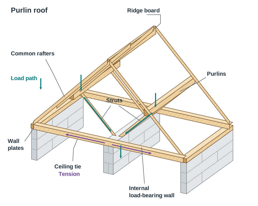
Typical Cut Roof Types
- Couple roof: Rafters and a ridge board only. Suited only to very small spans (such as sheds) because rafter thrust pushes external walls outward.
- Close couple roof: Adds horizontal ceiling ties at wall-plate level to resist rafter thrust. This is the standard cut roof for modest domestic spans.
- Collar roof: Adds horizontal ties higher up the rafters (typically one-third of the way up the rise). This ties opposing rafters together, reduces spread, and stiffens the rafters while giving greater usable headroom below.
- Purlin (double) roof: Adds longitudinal beams called purlins supported on timber struts that bear onto internal load-bearing walls. Purlins break the rafter span, allowing standard timber sections to span up to the 7,500 mm syllabus limit.
Structural Framing Components
- Wall Plate (100 mm × 75 mm): Bedded in mortar on a damp-proof course (DPC) over the inner leaf of the external cavity wall. It spreads rafter loads evenly across the masonry and is tied down using 30 mm × 5 mm galvanised mild steel holding-down straps (minimum 1,000 mm long) at maximum 2 m centres.
- Common Rafters (typically 150 mm × 50 mm at 400 mm centres): Sloping timbers spanning from wall plate to ridge that carry the roof battens and covering.
- Birdsmouth: A right-angled triangular notch cut into the underside of the rafter to seat it flat on the wall plate. To prevent shear failure under load, the vertical cut depth must never exceed one-third of the rafter depth (for example, maximum 50 mm on a 150 mm deep rafter). Rafters are secured with 100 mm skew nails or proprietary framing anchors.
- Ceiling Joists (100–150 mm × 50 mm): Run horizontally between wall plates to carry ceiling plasterboard and act as essential structural ties resisting rafter thrust.
- Ridge Board (225 mm × 32 mm): A spine timber running along the apex that provides alignment and a solid nailing face for opposing rafters.
- Purlins (typically 175–225 mm × 75 mm) and Struts (125 mm × 50 mm): Horizontal purlins support rafters midway up the slope. Diagonal timber struts transfer purlin loads down to internal load-bearing walls.
- Collar ties: Horizontal members fixed between opposite rafters, usually at purlin level, that tie the rafters together, reduce spread, and stiffen the roof.
Hipped Roof Framing
Where two roof slopes meet at an external corner, a deep hip rafter runs diagonally from the ridge to the wall plate corner. Shorter jack rafters are birdsmouthed onto the wall plate and splay-cut against the hip rafter. An angle tie connects adjacent wall plates across the corner to prevent the plates from spreading under the concentrated thrust of the hip rafter.
Prefabricated Roof Trusses and Wind Bracing
Prefabricated trussed rafters are engineered triangular frames assembled off-site and craned into position. Within the 7,500 mm syllabus limit, trusses span wall to wall without requiring internal load-bearing walls, use less timber than cut roofs, and are fast to erect.
Member Forces and Gang Nail Plates
Truss members are joined in a single plane using gang nail plates—galvanised steel plates with integral punched teeth pressed hydraulically into both timber faces. In a standard Fink (or 'W') truss, load distribution creates distinct internal stresses:
| Member Type | Primary Stress | Structural Action |
|---|---|---|
| Top Chords (Rafters) | Compression | Carry the dead load of coverings and imposed snow and wind loads |
| Bottom Chord (Ceiling Tie) | Tension | Pulls inwards to stop outward spreading; supports ceiling finishes |
| Internal Struts | Compression | Run diagonally down from top chords to brace rafters against mid-span deflection |
| Internal Ties | Tension | Suspend the bottom chord to prevent the ceiling from sagging |
An attic truss is a specialised prefabricated truss designed with an open rectangular internal profile. It incorporates heavier bottom and top chords to create a central room space for an attic living area without requiring internal load-bearing partitions.
Erecting Trussed Rafters (Ordered Steps)
- Bed and strap the 100 mm × 75 mm wall plates, then check they are level and parallel. Trusses are manufactured to an exact span and will twist or deflect if the bearings are out of level.
- Store trusses vertically on level bearers raised off the ground on site, protected from weather, to prevent distortion and timber wetting.
- Position the first truss plumb at the gable wall and brace it temporarily back to the wall plate or scaffolding.
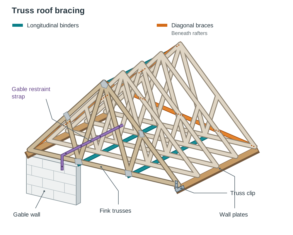
- Set out remaining trusses at design centres (typically 600 mm). Secure each truss foot to the wall plate using pressed galvanised steel truss clips; never skew-nail through gang nail plates or notch truss timbers.
- Nail temporary longitudinal battens across the top chords as work proceeds to keep each truss plumb and at the correct spacing.
- Fix permanent continuous timber longitudinal binders along the ceiling ties and at the apex.
- Install permanent timber diagonal braces fixed at approximately 45° to the undersides of the rafters, running from eaves to ridge, to prevent the entire roof from racking (leaning over under longitudinal wind loads).
- Secure the gable walls to the roof framing using 30 mm × 5 mm galvanised steel gable restraint straps anchored across at least three trusses, then proceed with the underlay and covering.
Never cut, notch, or drill any member of a prefabricated truss on site. A truss relies entirely on its complete triangulated geometry; cutting a single member causes structural failure.
Flat Roof Construction: Cold Deck vs Warm Deck (Up to 4,000 mm Span)
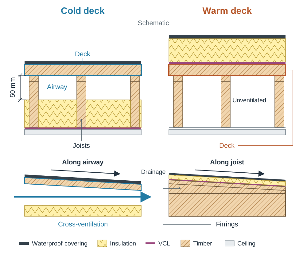
Timber flat roofs consist of structural joists (typically 150–200 mm × 50 mm) spanning up to the 4,000 mm syllabus limit. They are built with a designed fall of 1:40 (to ensure an installed fall of at least 1:80 after timber deflection) using tapered timber firring pieces nailed along the top edges of the joists before the 18 mm exterior-grade plywood or OSB3 decking is laid.
Dew Point and Condensation Risk
Air can hold only a limited amount of water vapour, and colder air holds less. The temperature at which moist air becomes saturated and drops its moisture as liquid water is its dew point. Condensation that forms inside the layers of a roof or wall, rather than on its room surface, is called interstitial condensation. This moisture causes hidden timber rot and destroys insulation performance.
Cold Deck Flat Roof
- Layer sequence (inside to outside): Plasterboard ceiling separate vapour control layer (VCL) insulation between joists continuous 50 mm unobstructed air gap structural timber deck waterproof roof covering.
- Performance problem: The structural timber deck sits on the cold outside of the insulation at ambient outdoor winter temperatures. If warm indoor vapour penetrates gaps in the ceiling VCL, it hits the cold underside of the deck and condenses. A continuous 50 mm cross-ventilation gap through opposite eaves is required to flush out this vapour. In practice, cross-ventilation in flat roofs is difficult to guarantee over wide spans, making cold decks prone to moisture failure.
Warm Deck Flat Roof (Best Practice)
- Layer sequence (inside to outside): Plasterboard ceiling structural timber joists 18 mm structural deck vapour control layer continuous rigid insulation (PIR or phenolic board) waterproof covering.
- Structural advantage: The joists and structural timber deck sit entirely on the warm, room side of the insulation boards. Keeping the deck warmer reduces the risk of interstitial condensation; insulation continuity and a correctly detailed vapour control layer are still essential. No ventilation gap is needed, so the roof void does not have to be vented to the outside air.
Flat Roof Finishes and Abutment Detailing
Flat roofs must be covered with an impermeable, durable waterproof layer and properly sealed wherever they meet an adjoining external wall.
Flat Roof Waterproof Finishes
- Built-up bituminous felt (three layers): The first layer (perforated or glass-fibre felt) is nailed or partially bonded to the deck to allow slight structural movement without tearing the membrane. The second and third layers are fully bonded in hot bitumen or torch-applied. Joints are staggered between layers so that laps never coincide. The surface is finished with a mineral-surfaced cap sheet or light-coloured stone chippings embedded in bitumen to reflect solar heat and protect the felt from ultraviolet (UV) degradation.
- Mastic asphalt: An isolating layer of sheathing felt is laid loose over the deck so movement in the timber does not crack the asphalt. Hot mastic asphalt is applied in two coats to a total thickness of approximately 20 mm, with joints between coats staggered by at least 150 mm. The surface is rubbed with sand or coated with solar-reflective paint. Asphalt forms a completely seamless, highly durable covering, but it is heavy and requires specialised heating equipment on site.
Abutments: Where a Roof Meets a Wall
An abutment is any junction where a roof meets a wall rising above it. Water running down the wall or driving into the joint must be prevented from penetrating the building fabric.
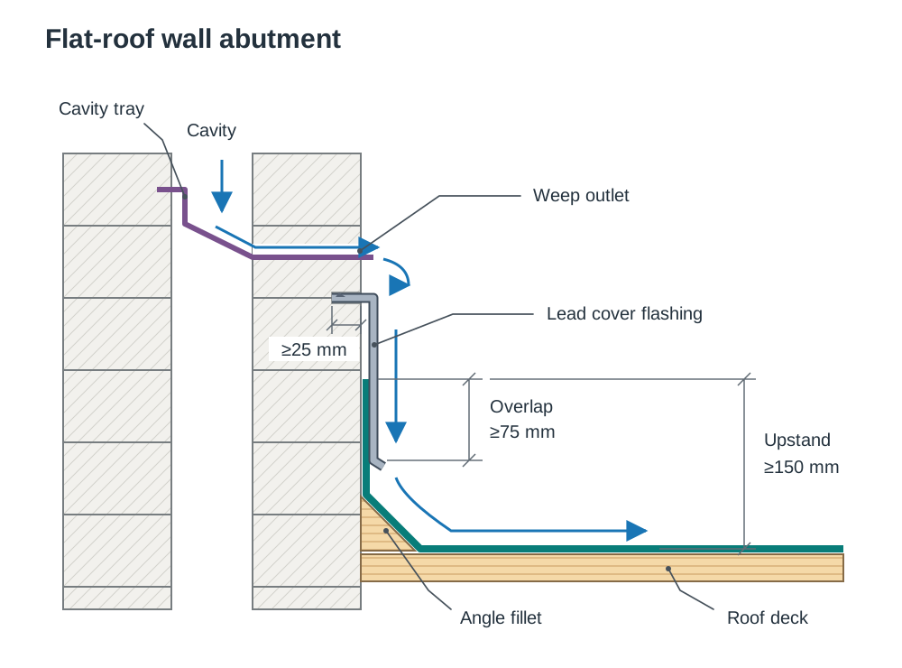
- Flat roof abutting an external wall:
- Fix a treated timber angle fillet into the internal corner where the deck meets the masonry wall. This allows the felt or asphalt to turn up the wall at an easy 45° angle rather than cracking across a sharp 90° bend.
- Carry the waterproof covering up the wall face over the fillet to form a vertical skirting or upstand at least 150 mm high.
- Build a stepped or continuous cavity tray with weep holes into the wall above the upstand to intercept any moisture tracking down the cavity and throw it onto the roof surface.
- Rake out a mortar joint at least 75 mm above the top of the upstand (minimum 25 mm deep).
- Tuck a lead cover flashing into the raked joint, secure it with lead wedges, and repoint with mortar. Dress the lead apron down over the roofing upstand by at least 75 mm to cover the skirting completely.
- Pitched roof abutting an external side wall: Under each course of slates or tiles, install a pre-bent lead soaker that rests on the batten and turns up the wall. Over the soakers, install a stepped cover flashing tucked into the horizontal mortar joints and dressed down over the upstands.
Roof Coverings, Verges, and Cold Roof Ventilation
Roof coverings shed rainwater by gravity and overlapping geometry, installed systematically from eaves to ridge.
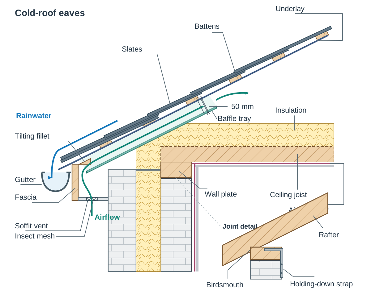
Sarking is the protective underlay beneath the battens and roof covering. In the timber roof detail here it is a breathable roofing membrane, with bitumen felt a traditional alternative. It directs water that gets past the slates or tiles towards the gutter; a breathable membrane also allows water vapour to pass outwards.
Single Lap and Double Lap Coverings
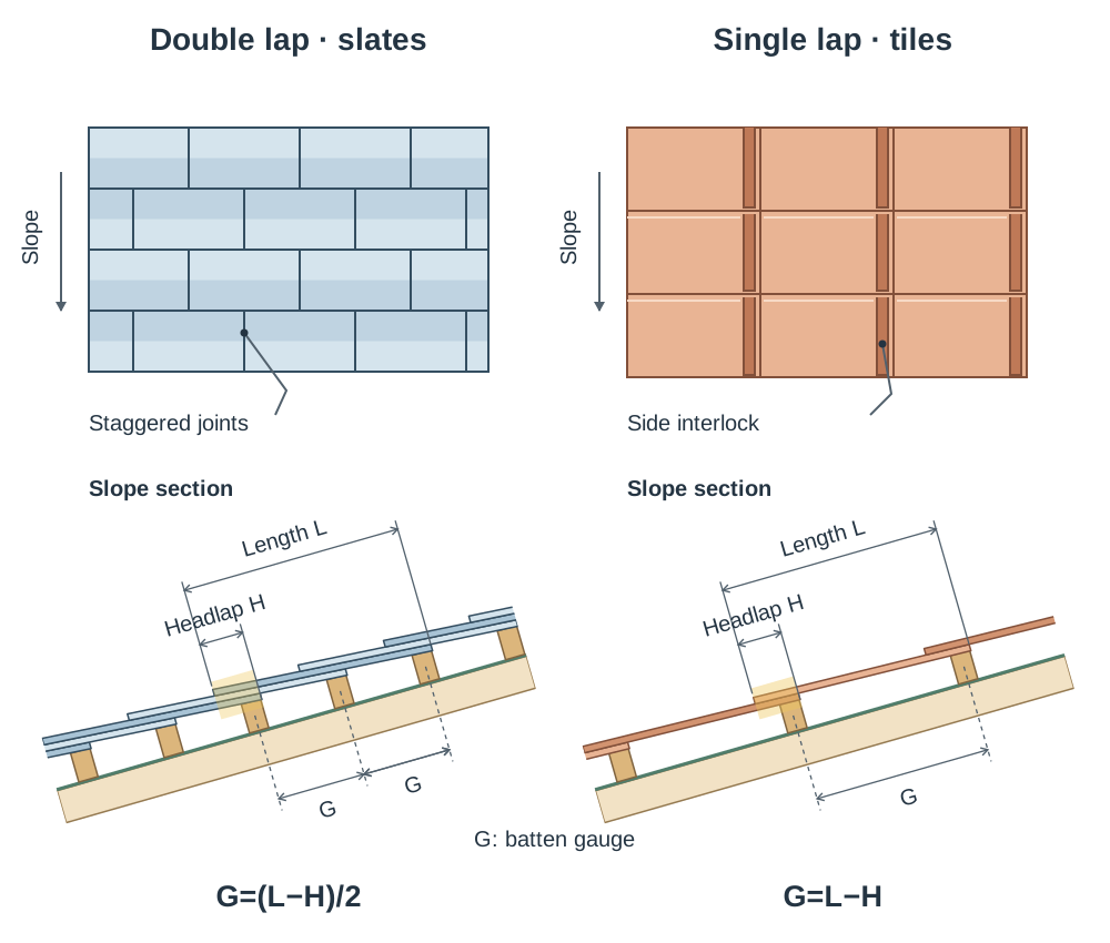
- Double lap (natural and fibre-cement slates): Slates have no interlocks. Each course must be overlapped by the two courses above it. The lower edge (tail) of each slate overlaps the head of the slate two courses below it; this overlap is the headlap. Every part of the roof is covered by at least two thicknesses of slate, and three thicknesses at the laps. Any rain entering the vertical joint between two slates lands safely on the centre of the slate directly beneath.
- Single lap (interlocking concrete or clay tiles): Each tile overlaps only the course immediately below it. Water is prevented from entering side joints by moulded interlocking ribs and drainage channels. Single-lap tiling is lighter, cheaper, and faster to lay, but requires a manufacturer-specified minimum pitch to prevent wind-driven rain penetration.
- Batten gauge (the centre-to-centre distance between battens):
Verges: The Sloping Edge at a Gable Wall
At a gable verge, the edges of slates or tiles must be secured against wind uplift and water penetration:
- Build the gable wall up to the underside of the roof covering. Tie it to the roof using 30 mm × 5 mm galvanised steel gable restraint straps fixed across at least three rafters or trusses.
- Bed a continuous strip of fibre-cement undercloak on mortar over the outer leaf of the gable wall. The undercloak tilts slightly inward toward the roof to direct run-off away from the gable face.
- Lay slates or tiles to overhang the undercloak by 38–50 mm, bedding them in mortar, or fit a proprietary dry-verge capping system that clips mechanically over the battens without wet mortar.
- Where the rafters overhang the gable wall on a cantilevered gable ladder, fix a timber or uPVC bargeboard to close the junction.
Cold Pitched Roof Ventilation Detailing
Ventilation carries away moisture-laden air before it condenses on cold timber. The conventional ventilated details below follow TGD F (2019); certified breathable-membrane systems may use a different condensation-control design.
- Pitch of 15° or greater, with insulation at a horizontal ceiling: Provide continuous eaves ventilation openings equivalent to a 10 mm slot along both opposite eaves.
- Pitch below 15°: Provide continuous eaves ventilation openings equivalent to a 25 mm slot along both opposite eaves.
- Insulation on the rafter slope (cathedral ceiling): For the conventional ventilated detail, provide 25 mm equivalent openings at opposite eaves, a continuous 50 mm clear airway above the insulation, and a continuous 5 mm equivalent opening at the ridge.
- Essential eaves components to draw: A continuous strip ventilator in the soffit (with insect mesh), a preformed plastic eaves baffle tray over the wall plate to stop quilt insulation from closing the 50 mm airway, and a timber tilting fillet behind the fascia to tilt the lowest slate course into the gutter.
Habitable Roof Spaces and Building Regulations
Converting an attic into a habitable bedroom (a storey-and-a-half or dormer configuration) requires compliance with Irish Building Regulations across three major pillars: structural stability, fire safety, and space standards.
Structural Requirements
Existing ceiling joists (typically 100 mm × 50 mm) are intended to carry the ceiling, not a habitable floor; their capacity depends on their span, spacing and timber grade. They are not designed as a floor, so the floor structure must be designed for the added loads. Usually this means new, deeper floor joists sized for the actual span, timber grade and spacing (225 mm × 50 mm is an illustrative size), designed for a domestic imposed floor load of 1.5 kN/m². These new joists must transfer their loads to suitable load-bearing walls or designed beams (which may include the inner leaf of an external wall or a steel universal beam), supported independently of the existing ceiling joists, which stay in place only to carry the ceiling below.
Stairways and Space Standards
The exact fire and stair provisions depend on the existing house, including its number of storeys, and the conversion design. Check the current TGD B and TGD K; typical provisions are outlined below.
Access to a habitable roof space typically uses a permanent stairway with a maximum pitch of 42° and a minimum clear headroom of 2.0 m along the pitch line. (TGD Part K permits reduced headroom in certain attic conversions; always verify current figures). Aim for a clear floor-to-ceiling height of about 2.4 m over at least half the floor area (commonly quoted design guidance).
Fire Safety and Means of Escape (TGD Part B)
A typical protected escape route has the staircase discharge into a protected hallway leading directly to an outside exit, enclosed by fire-resisting partitions fitted with self-closing fire doors (FD30 is commonly quoted in exam solutions; check the current TGD B Vol 2 rating). Typical provisions include mains-wired, interlinked smoke and heat alarms on all levels.
Where the design calls for one, provide an escape window with an unobstructed openable area of at least 0.33 m², with no dimension less than 450 mm high and 450 mm wide. The bottom of the openable area must be no more than 1,100 mm above the finished floor level. Where a low window cill requires guarding against falls under Part K, the guarding must not obstruct the emergency escape opening.
Model Exam Answer Structure (Attic Conversion Question)
When asked to discuss three functional requirements of an attic conversion in line with regulations, use structured headings with clear reasoning:
- Structural Stability (Floors and Roof): Existing ceiling joists are designed to carry the ceiling, not a habitable floor, so the floor must be designed for the added loads. Install new floor joists sized for the actual span, timber grade and spacing (225 mm × 50 mm is an illustrative size), designed for a 1.5 kN/m² domestic imposed load, bearing onto load-bearing walls or steel beams, isolated from the ceiling joists below. Sketch cue: Show new deep floor joists alongside existing ceiling joists bearing onto an inner masonry leaf.
- Fire Safety and Means of Escape: Attic occupants face extended escape routes during a fire. Design a protected escape route, suitable fire doors and alarms for the building’s storeys and layout. Where an escape window is required by the applicable design, its clear openable area must be at least 0.33 m², each dimension at least 450 mm, and the bottom of the opening no more than 1,100 mm above the floor. A 450 mm × 450 mm opening alone is too small to satisfy the area requirement. Sketch cue: Detail the escape window opening dimensions and cill height relative to the finished floor level.
- Thermal Envelope and Airtightness: Heat loss through the roof slope must be limited to prevent high heating costs and surface condensation. Install high-performance rigid PIR insulation between and below rafters, covered with an unbroken, taped airtight vapour control layer before plasterboarding. Sketch cue: Show insulation layers between rafters with a continuous taped membrane on the warm room side.
Key terms
- Birdsmouth
- A right-angled notch cut into the underside of a rafter (depth not exceeding one-third of the rafter depth) to give a level bearing on the wall plate.
- Wall Plate
- A horizontal timber (typically 100 mm × 75 mm) bedded on mortar on the inner masonry leaf to distribute rafter loads evenly along the wall.
- Gang Nail Plate
- A galvanised steel connector plate with punched integral teeth, pressed into timber joints under hydraulic pressure to form rigid truss joints.
- Warm Deck
- A flat roof build-up where insulation is placed entirely on top of the structural deck, keeping the deck and joists on the warm side and reducing the risk of interstitial condensation.
- Cold Deck
- A flat roof build-up where insulation is placed between joists below the deck, requiring a continuous 50 mm cross-ventilation gap to remove moisture.
- Firring Piece
- A tapered timber strip nailed along the top edge of horizontal flat roof joists to create a fall for rainwater drainage.
- Tilting Fillet
- A triangular timber strip fixed at the eaves to lift the tail of the first course of slates or tiles so it lies at the same angle as the rest and drains into the gutter.
- Headlap
- The distance by which the tail of an overlapping slate or tile extends past the head of the slate or tile in the course below it (or two courses below in double lap).
- Batten Gauge
- The centre-to-centre distance between roof battens, determined by the length of the covering unit and the required headlap.
- Purlin
- A longitudinal horizontal timber that supports common rafters midway along their slope, reducing deflection and permitting longer roof spans.
- Angle Fillet
- A triangular timber fillet placed at the 90° junction between a flat roof deck and an abutting wall to allow waterproof felt or asphalt to turn up without cracking.
- Undercloak
- A strip of fibre-cement board bedded in mortar along a gable wall head to support and slightly tilt the verge slates or tiles back toward the roof.
- Thermal Bridge
- A localised weak spot in the building envelope with high thermal conductivity (such as an uninsulated wall plate at the eaves) that conducts heat rapidly to the outside.
- Interstitial Condensation
- Water vapour condensing into liquid water within the hidden internal layers of a roof or wall structure when warm air reaches its dew point.
Check yourself
What is the maximum span for timber flat roofs and timber pitched roofs examined under the Leaving Certificate syllabus?
Timber flat roofs are examined up to 4,000 mm span, and timber pitched roofs are examined up to 7,500 mm span.
What primary structural stresses do the top chords and bottom ties experience in a prefabricated W-truss?
The sloping top chords experience compression forces, while the bottom ceiling tie experiences tensile forces (tension).
Where an escape window is required under the design provisions discussed here, what clear opening dimensions should be shown?
An unobstructed openable area of at least 0.33 m², with minimum dimensions of 450 mm high and 450 mm wide, and the bottom of the opening positioned no more than 1,100 mm above the finished floor level.
Why is a warm deck flat roof construction generally preferred over a cold deck flat roof?
Because the structural deck and joists are kept on the warm side of the insulation, which reduces the risk of interstitial condensation and removes the need for a cross-ventilation gap.
Calculate the batten gauge for a double-lap roof using 600 mm slates with a 100 mm headlap.
Gauge = (600 mm - 100 mm) / 2 = 500 mm / 2 = 250 mm.
What is the purpose of an angle fillet in flat roof abutment detailing?
It provides a 45° transition at the junction between the horizontal deck and the vertical wall, allowing the waterproof felt or asphalt to turn up the wall without cracking across a sharp 90° bend.