
Question 1 is the compulsory scale drawing question on the Higher Level Construction Studies written examination. It carries 120 marks out of the 300-mark written paper. Because the written paper represents 300 of the 600 total subject marks (the practical woodwork test and the student project provide 150 marks each), Question 1 alone accounts for 20%—one full fifth—of your overall Construction Studies grade. In a three-hour written exam, allocate roughly 70 minutes to Question 1 and approximately 27 minutes to each of your four chosen 45-mark questions. A disciplined 70-minute schedule breaks down into 5 minutes reading the brief and noting cut-offs, 5 minutes calculating heights and sheet layout, 35 minutes instrument drafting, 15 minutes dimensioning and annotating, and 10 minutes on Part (b) and continuity checks.
Reading the Brief, Dimensioning, and Sheet Set-Out
Every Question 1 begins with a detailed written brief specifying the building elements, materials, and strict vertical limits. Before picking up a pencil, read the brief with a highlighter or pen to mark four essential constraints:
- The drawing scale: typically 1:5 or 1:10 (or 1:20 for staircases and general sections).
- The lower cut-off limit: such as the base of the strip foundation or 300 mm below the window cill.
- The upper cut-off limit: such as 200 mm above the window head, 400 mm above a flat roof abutment, or the ridge.
- Required dimensions: past papers routinely state an exact instruction, such as 'Include four typical dimensions'.
Drawing past the requested cut-offs wastes time you need for labelling; stopping short forfeits baseline marks.
Dimensioning Conventions on the Section
Dimensioning marks are assessed independently of descriptive labels. Follow standard technical conventions:
- Draw dimension lines as thin, continuous lines parallel to the measured element, terminated by solid arrowheads or consistent 45° oblique slashes.
- Run projection (extension) lines from the feature, starting with a visible 1 mm to 2 mm gap from the element outline and extending slightly beyond the dimension line.
- Place the dimension figure above a horizontal dimension line and to the left of a vertical dimension line so it reads from the bottom or right side of the sheet.
- State all figures in actual building millimetres, never the scaled paper size, and omit the 'mm' unit label (for example, write 350, not 350 mm or 70).
- Keep dimension lines outside the construction profile. Place component dimensions closest to the drawing and overall dimensions further out.
- When asked for four typical dimensions, select four that prove structural compliance: overall wall thickness (350), cavity width (150), concrete floor slab thickness (150), and strip foundation width (900).
Linework Hierarchy and Scale Calculation
Examiners look for immediate contrast in line weights. What the imaginary saw has cut through must be distinctly darker than uncut surfaces:
- Cut outlines: Use an HB or B pencil, sharpened to a clean chisel point, to produce a bold, dense black outline around all sectioned solids (concrete, blockwork, structural timber).
- Secondary linework: Use a 2H or 3H pencil for surfaces seen in elevation beyond the cutting plane, hatching patterns, dimension strings, projection lines, and leader lines.
- Construction lines: Use 3H or 4H pencil with very light pressure for initial set-out.
- Scale conversion: Divide real dimensions by the scale denominator before drafting. At 1:5 scale, a 100 mm block measures 20 mm on paper, and a 150 mm cavity measures 30 mm. At 1:10 scale, a 100 mm block measures 10 mm on paper. Print a neat title and the stated scale at the base of the drawing (such as 'VERTICAL SECTION THROUGH EXTERNAL WALL AND GROUND FLOOR — SCALE 1:5').
Sheet Layout and Break Lines
Measure your drawing sheet, rule a 10 mm border, and leave a 40 mm margin on the right for annotations. Establish the finished floor level (FFL) as your master datum line approximately two-thirds of the way down the page, and project measurements up and down from it. When a full vertical section exceeds the page height—such as a section running from the foundation to a first-floor window—insert a standard zig-zag break line through a plain, uninterrupted stretch of wall. Never place a break line through a critical structural junction, opening, or floor-to-wall intersection.
Substructure and Solid Ground Floor Detailing
The substructure transmits structural loads safely to the subsoil while providing an impervious barrier against groundwater and hazardous soil gases.
Strip Foundation Sizing and the 45° Load-Spread Rule
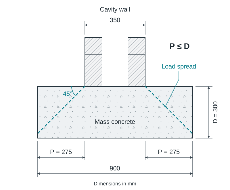
A mass concrete strip foundation spreads the wall load onto the subsoil at approximately 45°. Because unreinforced concrete is weak in tension, the projection (toe) on either side of the wall must not exceed the depth of the concrete: P ≤ D. If the toe projects further than the concrete is deep, the footing experiences bending and shear stresses that require bottom-zone steel reinforcement.
For a standard 350 mm cavity wall on a 900 mm wide strip foundation:
Because P = 275 mm, the foundation depth must be at least 275 mm. Draw it 300 mm deep. Domestic foundations are typically 600 mm to 900 mm wide and 225 mm to 300 mm deep, cast from C20/25 or C25/30 concrete. The base of the foundation must rest on firm, undisturbed subsoil at a minimum depth of 450 mm below finished ground level to remain below the frost line. In shrinkable clay soils or near mature trees, deepen the foundation to at least 900 mm.
Solid Ground Floor Build-Up (from subsoil up)
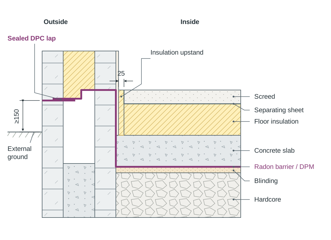
- Compacted hardcore bed: 150 mm to 225 mm of clean, well-graded, non-pyritic crushed stone (Clause 804 / T2 Granular Fill) compacted in layers.
- Sand blinding: 25 mm to 50 mm of fine sand spread over the hardcore to form a smooth surface that prevents sharp stones from puncturing the overlying membrane.
- Radon barrier / damp-proof membrane (DPM): minimum 1200-gauge (300 µm) low-density polyethylene sheet laid across the blinded bed. The membrane runs continuously over the inner leaf, steps down across the cavity, and laps seamlessly with the horizontal damp-proof course (DPC) in the outer leaf at least 150 mm above ground level.
- Concrete subfloor slab: 150 mm structural concrete slab (C20/25).
- Floor insulation: 120 mm to 150 mm of rigid polyisocyanurate (PIR) boards (or expanded polystyrene, EPS) laid tightly edge-to-edge.
- Separating layer: 500-gauge polythene slip sheet laid over the insulation to prevent wet screed slurry from penetrating insulation board joints.
- Perimeter edge upstand: a 25 mm vertical strip of rigid PIR insulation placed against the inner block leaf around the room perimeter, extending from the horizontal insulation to the top of the screed. This breaks the thermal bridge between the heated floor screed and the cold inner wall leaf.
- Floor screed: 65 mm to 75 mm sand-cement screed receiving the final floor finish.
Superstructure: Cavity Blockwork, Airtightness, and Timber Frame
The superstructure must carry gravity and wind loads, prevent rain penetration, retain internal heat, and seal the building against air leakage.
Concrete Block Cavity Wall
A standard 350 mm masonry cavity wall consists of:
- Outer leaf: 100 mm concrete block finished externally with a two-coat sand-cement render or facing brick.
- Cavity: 150 mm wide, filled either entirely with rigid PIR insulation or bonded EPS beads, or partially filled with 100 mm rigid insulation leaving a 50 mm clear residual drainage cavity against the outer leaf.
- Wall ties: stainless steel ties with built-in drip features sloping down towards the outer leaf. Space ties at maximum 900 mm horizontal and 450 mm vertical centres (tightened to 750 mm horizontal centres for 150 mm cavities). At all door and window reveals, install extra ties within 225 mm of the opening at maximum 300 mm vertical centres.
- Inner leaf: 100 mm solid concrete blockwork supporting intermediate floors and roof loads.
- Internal wet plaster: 13 mm two-coat gypsum plaster. The wet plaster (or a parge coat behind dry-lining) forms the primary room airtightness barrier. It must be carried down past the skirting board directly onto the concrete subfloor slab and sealed with airtightness tape.
Level-Access External Door Threshold
At an external door opening, weather exclusion, insulation continuity, and wheelchair accessibility must be resolved together:
- The subfloor insulation continues under the threshold, sealed with a vertical rigid insulation upstand to prevent thermal bridging between the internal screed and the external sub-cill.
- The floor radon barrier / DPM is brought up and lapped with a flexible stepped cavity tray / DPC under the threshold.
- Install a proprietary thermally broken, low-profile aluminium threshold unit with a maximum upstand of 15 mm and chamfered edges, bedded in continuous sealant on the DPC.
- Place an external drainage channel with an open grating directly outside the door, with paving falling away at 1:60 to prevent ponding.
Timber Frame Superstructure
A factory-manufactured timber frame wall features:
- A 100 mm concrete block outer leaf separated from the timber panel by a 50 mm clear, drained, ventilated cavity.
- A breather membrane fixed across the outer face of the sheathing board (9 mm to 12 mm OSB3 or plywood), shedding rain while allowing internal timber moisture to escape.
- Structural studs: 140 mm × 44 mm treated softwood studs at 400 mm or 600 mm centres, packed with mineral wool or rigid insulation.
- A vapour control layer (VCL) and airtightness membrane fixed to the warm room face of the studs, with all laps taped.
- A service cavity formed with 38 mm × 38 mm horizontal timber battens, accommodating cables and plumbing pipes without puncturing the VCL, lined with 12.5 mm plasterboard.
Wall Openings: Lintels, Cills, and Reveals
Forming an opening interrupts the cavity and insulation layer, creating paths for moisture ingress and cold bridges.
Window Head and Lintel Detailing
- Structural lintels: separate precast prestressed concrete lintels carry the inner and outer leaves, or a single thermally broken pressed-steel lintel spans the full wall width.
- Cavity tray DPC: a flexible stepped DPC tray sits over the lintel, sloping downward from the inner leaf to the outer leaf. It intercepts cavity water and discharges it through plastic weep holes placed in open perpend joints at maximum 450 mm centres.
- Head insulation: an insulated closer or rigid insulation board is fitted between the two lintels to maintain unbroken thermal resistance.
Window Cills and Reveals
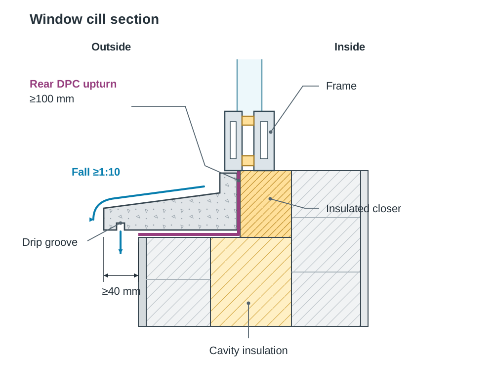
- Sub-cill: a precast concrete or pressed aluminium sub-cill set with a minimum fall of 1:10, projecting at least 40 mm clear of the finished render. It must incorporate a continuous capillary drip groove on its underside.
- Cill DPC: a continuous flexible DPC bedded beneath the sub-cill, turned up at least 100 mm at the rear and sides to form a waterproof tray.
- Cavity closer: proprietary insulated cavity closers seal the cavity at jambs and cills, preventing cold bridging and draught loops while offering a firm backing for airtightness tapes.
- Frame alignment: thermally broken window frames must sit within the insulated layer of the cavity, set back behind the outer block leaf reveal by 20 mm to 30 mm.
Roof-to-Wall Junctions: Cold Pitched, Warm Flat, and Sloped Ceilings
Roof detailing must resolve structural support, wind anchorage, continuous insulation, and positive ventilation.
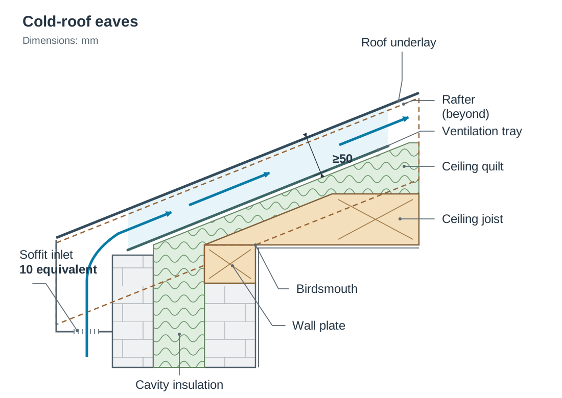
Cold Pitched Roof (Insulation at Ceiling Level)
- Wall plate: 100 mm × 75 mm preservative-treated softwood wall plate bedded in mortar on the inner leaf, anchored with galvanised steel holding-down straps (30 mm × 2.5 mm) fixed to the blockwork at 1.2 m centres.
- Rafters: cut with a birdsmouth joint (depth not exceeding one-third of the rafter depth) bearing fully across the 100 mm × 75 mm wall plate, nailed securely to horizontal ceiling joists.
- Eaves ventilation inlet: a continuous vented soffit strip or over-fascia vent with insect mesh, providing an opening equivalent to a continuous 10 mm gap along the eaves on opposite sides of the building.
- Clear air space: a proprietary corrugated eaves ventilation tray fitted over the wall plate holds ceiling quilt insulation back from the roof underlay, maintaining a clear air path of at least 50 mm between the top of the insulation and the underlay.
- Ridge ventilation outlet: install a dry-ridge vent system or ridge vent tiles providing a continuous high-level outlet to exhaust warm, moisture-laden air through cross-ventilation.
- Thermal continuity: 300 mm of quilt insulation (100 mm between ceiling joists, 200 mm cross-laid over joists) extends over the wall plate to meet the cavity insulation without closing the 50 mm ventilation gap.
Sloped Ceiling / Rafter-Level Insulation (Attic Conversion / Dormer)
Where a room is built into the roof space, insulation moves from the ceiling to the rafters:
- Slates or concrete tiles fixed to 50 mm × 35 mm treated timber battens.
- Vapour-permeable breather membrane fixed across rafters (counter-battens added if a non-breathable underlay is used).
- Clear air path: a 50 mm clear ventilated air space maintained directly under the underlay.
- Eaves inlet: continuous over-fascia or soffit vent sized to an equivalent 25 mm continuous opening.
- Ridge outlet: continuous dry-ridge vent equivalent to a 5 mm continuous opening.
- Rafters: 175 mm × 44 mm rafters with rigid PIR insulation cut tightly between them, finishing 50 mm below the underlay.
- Thermal bridge break: a continuous layer of 50 mm to 60 mm rigid PIR fixed across the underside of the rafters.
- Internal seal: a vapour control layer on the warm room side with all joints taped, lined with 12.5 mm plasterboard and skim.
Warm Deck Flat Roof
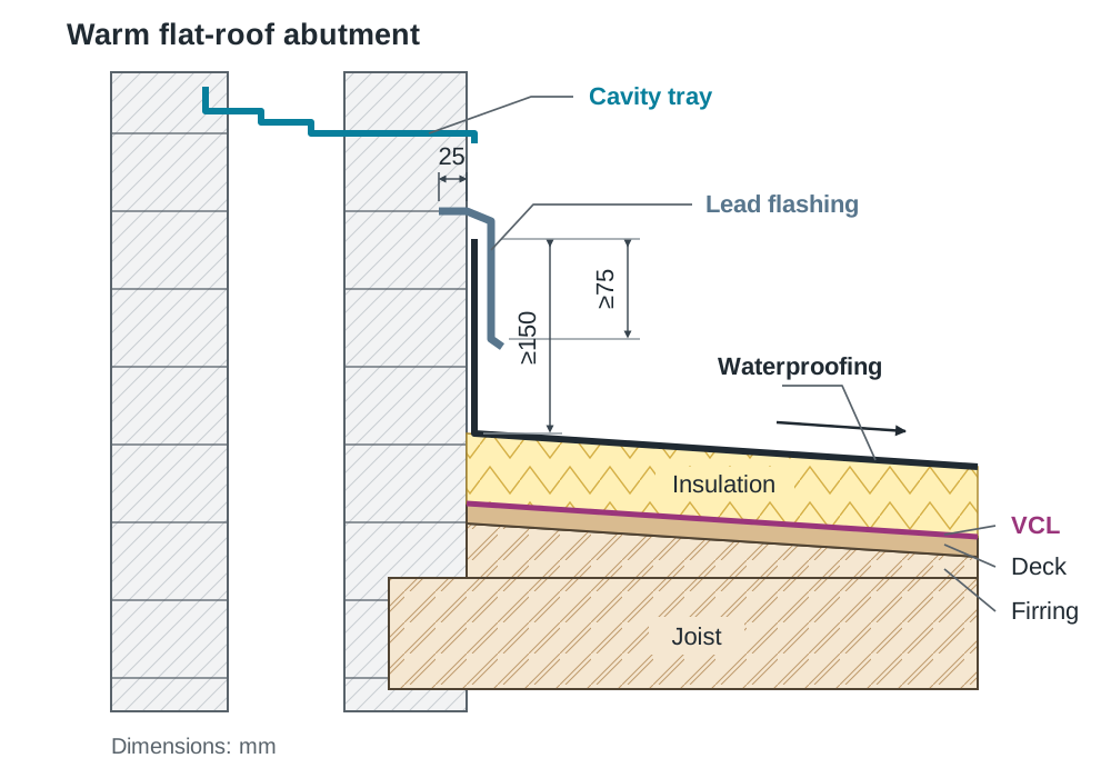
- Joists: 200 mm × 44 mm softwood joists fitted with tapered firring pieces providing a minimum design gradient of 1:40 (achieving a finished fall of at least 1:80 after timber deflection), covered with 18 mm WBP plywood or OSB3 deck.
- VCL: a heavy-duty reinforced vapour control layer bonded directly to the plywood deck.
- Insulation: 120 mm to 160 mm rigid PIR boards bonded on top of the VCL. In this warm deck roof, the VCL sits on the warm room side of the insulation, keeping the timber joists and structural deck at room temperature and eliminating condensation risks.
- Waterproofing: three-layer built-up bituminous felt or single-ply EPDM membrane dressing up abutting walls by at least 150 mm.
- Abutment flashing: Code 4 lead flashing stepped into a mortar joint 25 mm deep, secured with lead wedges, and lapping down over the roof upstand by at least 75 mm beneath a stepped cavity tray.
Internal Floors, Staircase Geometry, and Timber Construction
Internal details require structural stability, acoustic isolation, and strict dimensional safety.
Suspended Timber Ground and Upper Floors
- Ground floor void: suspended ground floor joists bear on wall plates seated on DPCs atop honeycombed sleeper walls or galvanised joist hangers. The void below must be cross-ventilated using external airbricks and telescopic cranked cavity sleeves, providing at least 1,500 mm² of free ventilation area per metre run of external wall (or 6,000 mm² per m² of floor area). Maintain a clear air space of at least 150 mm between the oversite concrete slab and the underside of the joists (and at least 75 mm below wall plates).
- Upper floors: 225 mm × 44 mm joists bearing 90 mm onto the inner leaf or supported in galvanised hangers. Floor openings (stairwells) are framed using doubled trimming joist members and trimmer joists connected with steel framing anchors. Install solid timber strutting (38 mm thick) or herringbone strutting at mid-span to stop joists twisting under load.
Staircase Regulatory Geometry and Detailing
Measure vertical stair dimensions from finished floor level to finished floor level:
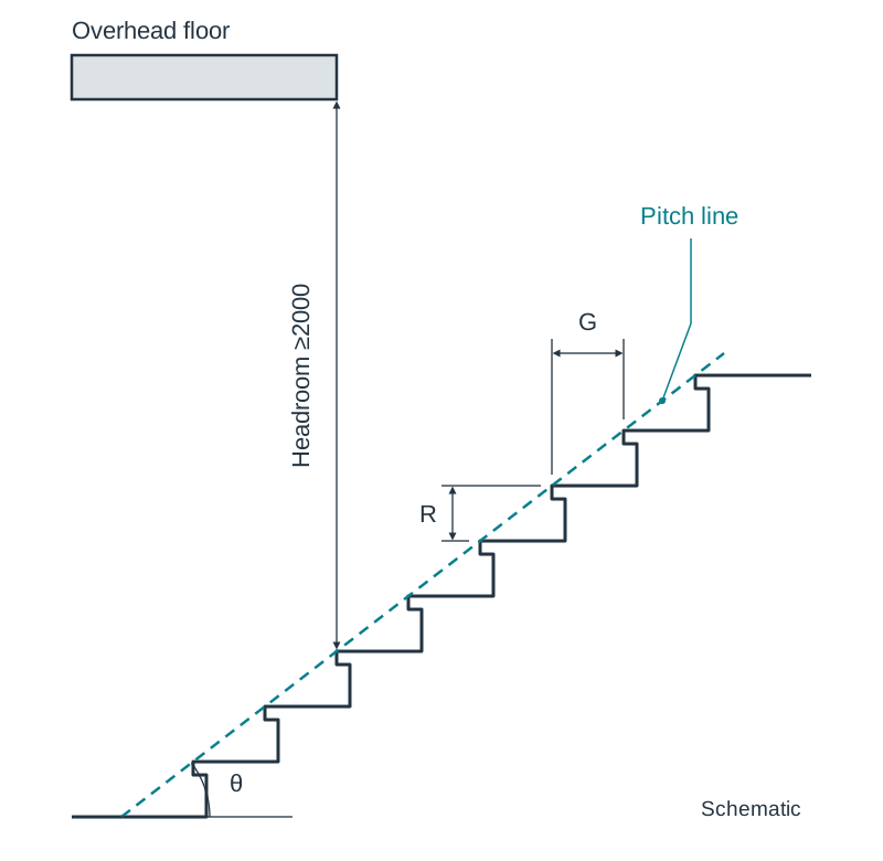
- Rise: the vertical height of one step. For a private domestic stair, the maximum permitted rise is 220 mm and the minimum is 115 mm.
- Going: the horizontal distance between successive nosings. For a private domestic stair, the minimum permitted going is 220 mm.
- The 2R + G rule: twice the rise plus the going must total between 550 mm and 700 mm (). This maintains a natural walking stride.
- Pitch line and clearance: the maximum stair pitch is 42° (calculated from ). Clear headroom must measure at least 2.0 m vertically above the pitch line.
- Constructional components: timber strings (32 mm to 38 mm thick) housed 12 mm to 15 mm deep to receive treads (22 mm to 25 mm) and risers (16 mm to 19 mm), wedged and glued. Fit triangular glue blocks in the internal junctions between treads and risers. Balusters must be spaced so that a 100 mm sphere cannot pass through any opening, with the handrail set 900 mm to 1,000 mm above the pitch line.
Standard Hatching Symbols and the 'Name–Size–Function' Annotation Method
Marks in Question 1 are awarded element by element for items accurately drawn and identified. A drawing that names a material without giving its size or purpose earns only partial credit.
The Name–Size–Function Formula
Rule a crisp horizontal leader line ending in a clear arrow touching the component, and write a three-part note:
- Name: the precise material name (e.g. Rigid Polyisocyanurate (PIR) Insulation).
- Size: the true building dimension in millimetres (e.g. 150 mm thick).
- Function: the technical reason for its installation (e.g. Minimises heat loss and prevents thermal bridging between floor screed and rising wall).
Material Hatching Conventions
- In-situ concrete: light stippling with fine dots and small, randomly scattered triangles.
- Concrete blockwork: 45° diagonal parallel lines ruled lightly and evenly spaced. When two separate blocks or masonry units meet, hatch them in opposite directions so the joint remains distinct.
- Structural timber in section: crisp diagonal cross (X) connecting opposite corners of the rectangular section.
- Thermal insulation: continuous uniform zig-zag or quilted wave pattern bounded by the element outlines.
- Compacted hardcore: interlocking angular stone profiles topped with fine sand stipple.
- Membranes (DPC, DPM, radon, VCL): single, bold continuous pencil lines clearly labelled with overlap details.
Key terms
- damp-proof course (DPC)
- A continuous horizontal or vertical impervious barrier (such as embossed polyethylene or bituminised polymer) built into walls at least 150 mm above ground level to stop rising damp via capillary action.
- damp-proof membrane (DPM)
- A heavy-duty waterproof polythene sheet (minimum 1200-gauge / 300 µm) laid beneath a concrete ground floor slab to stop moisture rising from the subsoil.
- radon barrier
- A certified gas-tight and waterproof membrane installed across the ground floor footprint and sealed to wall DPCs to prevent radioactive radon gas from entering the building.
- thermal bridge
- A localised zone of a building envelope having higher thermal conductivity than surrounding insulated materials, causing rapid heat loss, cold surface temperatures, and condensation.
- cavity closer
- An insulated component fitted into a cavity wall opening (window or door reveal) that closes the cavity, prevents cold bridging, and resists fire spread.
- birdsmouth joint
- A triangular notch cut into a roof rafter (not exceeding one-third of the rafter depth) that allows the rafter to bear flat and securely across the horizontal wall plate.
- firring pieces
- Tapered timber battens fixed to the top of flat roof joists to create a slope (minimum 1:40 design fall) for surface rainwater drainage.
- stepped cavity tray
- A preformed or site-dressed stepped waterproof barrier bridging a wall cavity above an opening or roof abutment to capture downward water and discharge it through weep holes.
- vapour control layer (VCL)
- A continuous membrane installed on the warm room side of thermal insulation to prevent warm, moisture-laden indoor air from entering cold building layers and condensing.
- eaves ventilation tray
- A preformed corrugated plastic tray installed between rafters over the wall plate that holds quilt insulation back to keep a continuous 50 mm air path into the roof.
- lead flashing
- A malleable sheet metal profile (commonly Code 4 lead) dressed into a wall mortar joint and lapped over roof upstands to form a watertight seal against driving rain.
- trimming joist
- A doubled or reinforced structural joist that carries the ends of trimmer joists around a floor opening such as a stairwell.
- strutting
- Solid timber pieces (38 mm thick) or criss-crossed timber battens (herringbone) fitted between floor joists at mid-span to prevent joists twisting or buckling under load.
- rise
- The vertical distance from the top of one stair tread to the top of the next step (maximum 220 mm, minimum 115 mm for private domestic stairs).
- going
- The horizontal distance from the nosing of one stair tread to the nosing of the next tread (minimum 220 mm for private domestic stairs).
- pitch line
- A straight notional line connecting the leading nosings of all treads in a stair flight, which must not exceed an angle of 42° to the horizontal.
- headroom
- The unobstructed vertical distance measured from the pitch line of a stair to the ceiling or overhead structure, which must be at least 2.0 m throughout the flight.
- breather membrane
- A water-resistant yet vapour-permeable membrane fixed on the external face of timber frame sheathing that resists wind-driven rain while allowing internal moisture to escape.
- sheathing
- Structural sheet board (such as 9 mm to 12 mm OSB3 or plywood) fixed directly to timber studs to provide lateral racking resistance against wind loads.
- wall plate
- A 100 mm × 75 mm preservative-treated timber plate bedded in mortar atop the inner block leaf to distribute roof or floor joist loads and anchor them against wind uplift.
- warm deck roof
- A flat roof construction where thermal insulation is positioned entirely above the structural roof deck and vapour control layer, keeping the deck and joists warm.
- weep holes
- Open vertical perpends or plastic drainage outlets spaced at maximum 450 mm centres in the outer block leaf directly above cavity trays to drain moisture externally.
Check yourself
What are the scaled paper dimensions of a 350 mm cavity wall and a 150 mm concrete floor slab drawn at 1:5 scale?
The 350 mm wall measures 70 mm on paper (350 / 5), and the 150 mm slab measures 30 mm on paper (150 / 5).
What is the primary function of a 25 mm rigid insulation upstand installed around the perimeter of a ground floor screed?
It eliminates the thermal bridge at the floor-to-wall junction by stopping heat from conducting horizontally out of the warm screed into the colder inner block leaf.
A cold roof has 300 mm of quilt insulation at ceiling level. What size of eaves opening is required, how much clear air space must be maintained above the insulation, and what component ensures this?
An eaves inlet equivalent to a continuous 10 mm gap is required on two opposite sides; at least 50 mm of clear air space must be kept between the insulation and the underlay; and a proprietary corrugated plastic eaves ventilation tray fitted over the wall plate holds the quilt back to maintain this path.
State the standard Building Regulations comfort formula for domestic staircase step proportions.
550 mm <= 2R + G <= 700 mm, where R is the individual riser height and G is the individual going distance.
What is the minimum permitted depth of a domestic strip foundation below finished ground level?
At least 450 mm below finished ground level to remain below the zone affected by seasonal frost; this increases to at least 900 mm in shrinkable clay soils or near trees.
What three distinct pieces of information must be included in a 'Name–Size–Function' drawing annotation?
The precise material name, its specific dimension in millimetres, and a brief functional justification explaining why the component is installed.