
Every house needs two things from its plumbing: hot water at the taps, and heat in the rooms. In most Irish houses both are produced by the same boiler or heat pump, but the water that runs through the radiators is kept completely separate from the water you wash in. This topic covers how that separation is achieved in direct and indirect systems, how cold and hot pipework is laid out and controlled, how a fireplace and flue are built safely into a timber floor, and how to calculate steady-state heat losses, annual fuel costs, and payback periods under Irish Building Regulations.
Cold Water Supply: Direct vs. Indirect Systems
Mains water enters the site from the public utility main through an external boundary stopcock. It travels underground in a heavy-gauge alkathene or barrier pipe laid at a minimum depth of 750 mm to protect against frost damage. Inside the house, the pipe enters through the rising main, where an internal stopcock and drain cock are fitted immediately for emergency isolation and drainage.
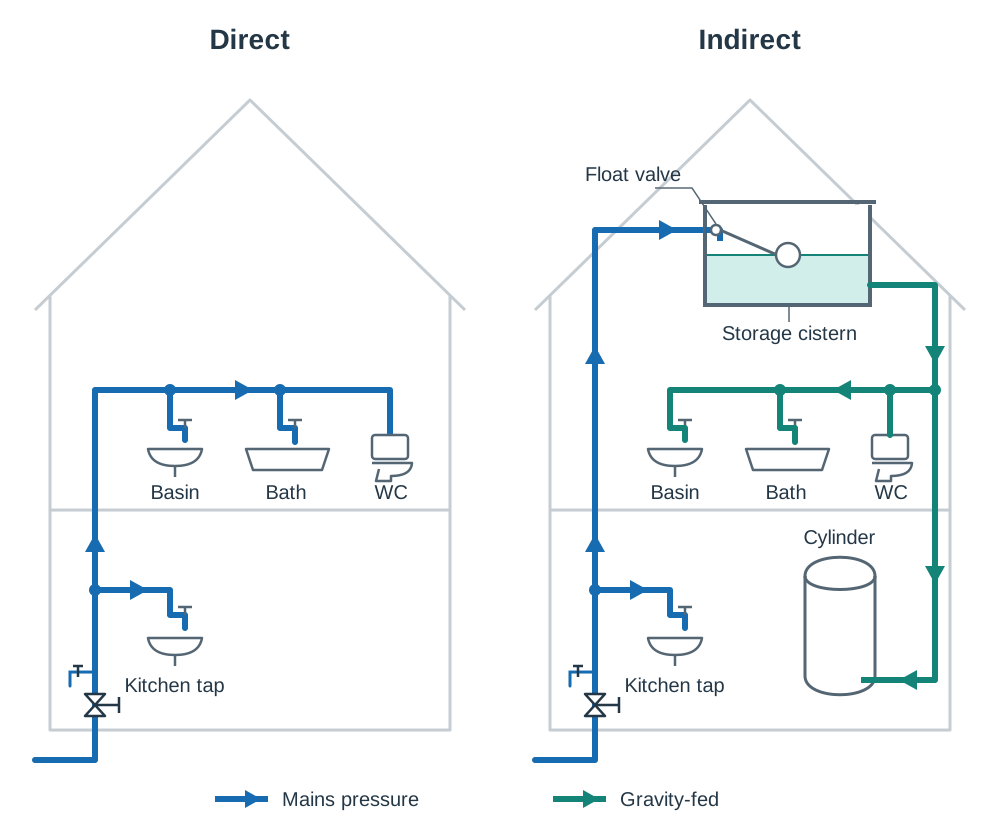
Direct Cold Water System
In a direct cold water layout, the rising main supplies every cold tap and appliance in the house directly at mains pressure, including the kitchen sink, wash hand basins, bath, shower, and WC cisterns.
- Advantages: drinking-quality water is available at every tap; no large storage cistern is needed in the attic, eliminating heavy roof loading and the risk of attic pipe freezing or tank contamination; less pipework is needed, which lowers installation costs.
- Disadvantages: there is no stored water reserve if the district mains supply is cut off; water pressure fluctuates noticeably when multiple outlets open simultaneously; high mains pressure increases wear on valves, fittings, and causes water hammer.
Indirect Cold Water System
In an indirect system, the rising main supplies only the kitchen sink tap directly. It then continues upward into the roof space to supply a cold water storage cistern through a float-operated ball valve. All other cold outlets—wash hand basins, bath, WC cisterns—and the cold feed down to the hot water cylinder are supplied from this attic cistern by gravity.
- Advantages: provides a reserve of stored water during mains interruptions; delivers steady, equal, low-pressure flow to sanitary fittings, which reduces noise, splashing, and valve wear; prevents high-pressure back-siphonage into the public main.
- Disadvantages: a full cistern imposes a substantial structural load on ceiling joists; stored water in the attic carries risks of freezing in winter and contamination if not tightly lidded; only the kitchen sink provides fresh, unstored drinking water.
Domestic Hot Water: Direct, Indirect, and Unvented Layouts
Water heated for central heating radiators must never mix with the domestic water used for bathing and washing. Radiator water turns black and corrosive over time, carrying rust particles, dissolved magnetite, and chemical inhibitors.
Direct Hot Water System
In a direct hot water system, the water drawn at the taps circulates straight through the boiler heat exchanger. Cold water from an attic storage cistern enters the bottom of the cylinder, flows through a low-level pipe to the boiler, heats up, and returns to the top of the cylinder via natural convection (thermosiphon circulation).
Direct systems have two critical drawbacks: fresh mains water continually passes through the boiler, depositing limescale that chokes pipework and acts as an insulating barrier on heat exchanger surfaces; aerated water also corrodes ferrous radiators, meaning central heating radiators cannot be connected to this circuit without contaminating tap water.
Indirect Hot Water System
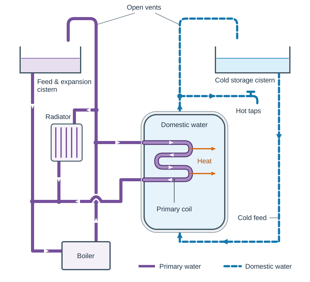
An indirect system keeps primary heating water and secondary domestic water isolated from each other:
- Primary circuit: A closed loop connects the boiler to a coiled copper pipe inside the cylinder, known as the primary heat exchanger (heating coil), and to the radiators. (A storage vessel heated this way is called a calorifier.) An attic feed and expansion cistern (typically 45 litres) tops up water losses and accommodates thermal expansion. Because this primary water recirculates indefinitely, it deoxygenates and deposits minerals only once, preventing progressive scale and allowing chemical corrosion inhibitors to be added.
- Secondary circuit: Domestic cold water drops from the cold storage cistern (230 L to 340 L) into the cylinder base, absorbs heat conductively across the wall of the primary coil, and warms up. Heated water rises by stratification and is drawn off from the top of the cylinder to the taps.
- Safety venting: Both open circuits require an open safety vent pipe terminating over their respective attic cisterns. The secondary vent rises from the cylinder top outlet and turns down over the cold storage cistern. The primary vent rises from the boiler flow and discharges over the 45 L feed and expansion cistern. Neither vent pipe may ever have an isolating valve fitted.
- Immersion heater: An electric heating element fitted directly into a threaded boss on the cylinder. Most modern cylinders have two elements: a short top element (sink) to heat a small volume quickly, and a long lower element (bath) to heat the full cylinder, often on cheaper night-rate electricity. It acts as a summer heat source when the boiler is switched off and serves as an emergency backup.
Unvented Hot Water Cylinders
An unvented cylinder connects directly to the incoming cold mains pipe, operating under mains pressure without attic cisterns or open vents.
Water expands in volume by roughly 2% across the normal domestic working range of 10 °C to 65 °C (and about 4% from 4 °C to 100 °C). Because an unvented cylinder has no open vent to the attic, it requires a three-stage mechanical safety hierarchy:
- An expansion vessel sized to roughly 10% of system water volume, fitted with a synthetic rubber diaphragm and nitrogen gas cushion to absorb thermal expansion.
- A working cylinder thermostat set to 60–65 °C, backed up by an independent high-limit thermal cut-out that isolates fuel or power at 85 °C.
- A temperature and pressure relief valve designed to lift if water reaches 90–95 °C or pressure exceeds 6 bar. This valve discharges safely through a copper pipe containing an open-air tundish, which offers a visible air break to prevent back-siphonage and indicate discharge.
Storage and Delivery Temperatures
Under Technical Guidance Document G (TGD G), domestic hot water must be stored at 60 °C to 65 °C. Storing water above 60 °C kills Legionella pneumophila, the bacterium responsible for Legionnaires' disease, which multiplies in tepid water between 20 °C and 45 °C. To prevent scalding at the outlet, a thermostatic mixing valve blends stored hot water with cold mains water to limit delivery to approximately 46–48 °C at baths and basins.
Cistern Support and Sealed Central Heating
Storage Cistern Support Details
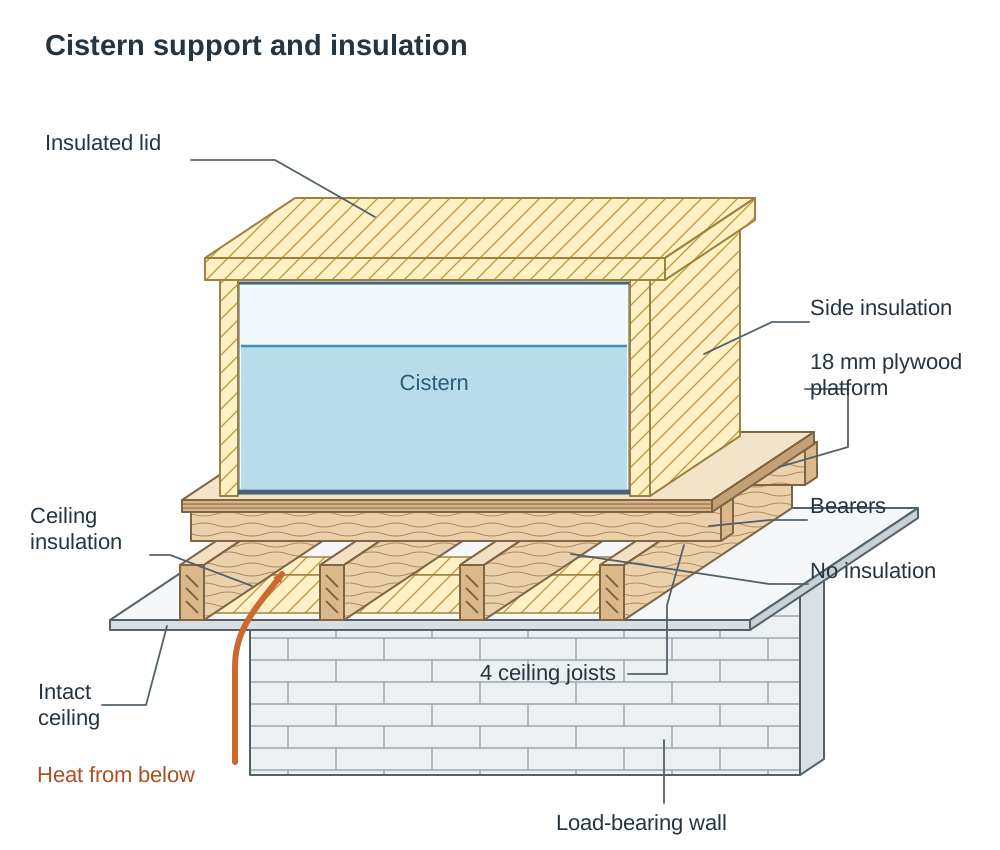
A full 230–340 litre cold storage cistern weighs 230–340 kg. Placing this concentrated dead load on ceiling joists requires robust framing: the cistern must rest on a flat, continuous platform of 18 mm exterior-grade WBP plywood or close-boarded timber. This platform rests on timber bearers spanning across a minimum of four ceiling joists, placed directly over an internal load-bearing wall to avoid ceiling sag.
The sides and lid of the cistern must be insulated with rigid insulation or glass wool, but the ceiling space directly below the cistern base must be left completely uninsulated. This deliberate detail allows warm air from the rooms below to rise into the cistern casing and prevent freezing in winter.
Sealed (Pressurised) Central Heating System
Unlike traditional vented heating circuits fed by an attic cistern, modern oil, gas, and heat-pump circuits are sealed systems operating at 1.0 to 1.5 bar cold pressure.
- Key components:
- A temporary braided filling loop connected to the mains with a double check valve, used to fill and pressurise the system and then physically disconnected.
- An expansion vessel containing an internal rubber diaphragm and nitrogen cushion that flexes as water expands when heated.
- A system pressure gauge located near the boiler to monitor pressure drops that signal leaks.
- A spring-loaded pressure relief safety valve calibrated to open at 3.0 bar, discharging outside through a copper safety pipe.
- An automatic air vent fitted at high points to vent trapped air without releasing water.
- Advantages: no attic cisterns (no freezing hazard, no risk of roof tank leaks, and freed attic space); higher system pressure prevents cavitation in the pump and allows radiators to be positioned higher up; faster warm-up and reduced corrosion because no air enters the circuit.
- Strict limitation: a sealed system cannot be connected to an uncontrolled solid-fuel appliance because solid fuel cannot be shut off instantly when pressure peaks.
Small-Bore Heating Pipework: One-Pipe vs. Two-Pipe
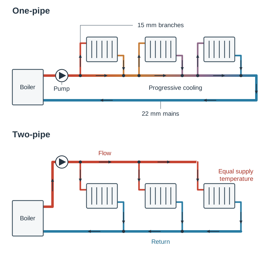
Domestic wet central heating distributes heated primary water through narrow copper or barrier-plastic pipes using an electric circulating pump. Distribution mains are typically 22 mm diameter, with 15 mm branches dropping to individual emitters.
One-Pipe System
In a one-pipe system, a single continuous pipe loop leaves the boiler flow, visits each radiator in turn, and returns to the boiler. Water diverted through a radiator exits back into the very same pipe. Radiators run hydraulically in series:
- Cooled water leaving the first radiator discharges back into the main run, progressively dropping the flow temperature for every subsequent emitter.
- For example, if boiler water leaves at 70 °C and each radiator drops temperature by 3 °C, the fifth radiator on the loop receives water at only 58 °C.
- Later radiators must be progressively oversized to deliver their rated output, and closing one radiator upsets flow and temperature along the rest of the loop.
Two-Pipe System
In a two-pipe system, radiators are connected in parallel across two separate pipes: a dedicated flow pipe and a dedicated return pipe.
- The flow main delivers primary water at the same initial boiler design temperature (typically 65 °C to 75 °C) to the inlet of every emitter.
- The return main collects cooled water from radiator outlets and returns it directly to the boiler.
| Feature | One-Pipe System | Two-Pipe System |
|---|---|---|
| Piping layout | Single series loop feeding and returning to same pipe | Separate, parallel flow and return pipes |
| Supply temperature | Drops progressively at each successive radiator | Identical design temperature delivered to all radiators |
| Radiator sizing | Radiators at end of circuit must be oversized | Sized solely to match the heat loss of each room |
| Balancing and control | Difficult; altering one valve affects entire ring | Balanced easily using lockshield valve at each emitter |
| Capital cost | Less pipework; cheaper to install | Requires roughly double the pipework; higher initial cost |
| Current status | Obsolete in new construction | Standard specification for domestic wet systems |
System Controls and Methods of Heat Conservation
Building Regulations Part L (Conservation of Fuel and Energy) mandates independent time and temperature controls across domestic space heating and hot water services.
Essential System Controls
- Motorised zone valve: An electrically operated valve that opens or closes flow to a specific heating zone (such as upstairs bedrooms, ground-floor living rooms, or hot water cylinder).
- Cylinder and room thermostats: The cylinder thermostat is strapped to the cylinder surface one-third of the way up from the base, set to 60–65 °C. Room thermostats detect air temperature and switch zone valves when comfort levels are met.
- Boiler interlock: An electrical wiring arrangement that ensures the boiler and circulating pump shut down completely whenever all room and cylinder thermostats are satisfied. This prevents the boiler firing on its internal thermostat when no heat is demanded.
- Thermostatic radiator valve (TRV): A self-acting valve fitted to radiator inlets that senses local air temperature via an expanding wax or liquid capsule, throttling flow to the radiator without needing an electrical connection.
- Condensing boiler: Recovers the latent heat of vaporisation from water vapour produced during combustion by passing flue gases through an extra-large secondary heat exchanger. This achieves a seasonal efficiency above 90%. To allow condensing, heating return water must arrive back at the boiler below 55 °C. The resulting acidic condensate must drain continuously through an insulated plastic pipe to an internal waste stack or external gully.
Ten Methods of Heat Conservation
- Cylinder insulation: Fit a factory-insulated cylinder with at least 50–80 mm of polyurethane foam (or an 80 mm lagging jacket) to minimise standing heat loss.
- Pipework lagging: Insulate all primary and secondary pipework runs, especially pipes passing through unheated attics, crawl spaces, and floor voids.
- Short dead legs: Keep the cylinder positioned close to bathrooms and kitchens so water sitting in supply pipes between uses is minimised.
- Calibrated cylinder thermostat: Set storage to 60–65 °C so fuel is not wasted generating excessively hot water.
- Time and zone programmers: Install digital 7-day multi-channel programmers so space heating and hot water run only during occupied hours.
- Boiler interlock wiring: Wire controls so the burner and pump extinguish when zones achieve their temperature set points.
- Individual TRVs: Fit thermostatic valves to radiators in bedrooms (setting them to 16–18 °C) while leaving main living rooms higher.
- High-efficiency heat generators: Replace conventional boilers with condensing units (efficiency >90%) or heat pumps.
- Radiator reflective foil: Install reflective foil behind external-wall radiators and position curtains clear of radiator tops.
- Fabric-first envelope: Maximise wall, floor, and roof insulation, maintain airtightness, and fit triple glazing to lower the gross heating load before sizing heating equipment.
Underfloor Heating, Heat Pumps, and Flues at Suspended Floors
Underfloor Heating (UFH)
Underfloor heating embeds continuous coils of cross-linked polyethylene (PEX) or polybutylene pipe into a concrete screed laid over high-density insulation. The entire floor becomes a radiant heat emitter.
- Water temperature: Operates at 30 °C to 45 °C, compared to 60 °C to 75 °C for panel radiators, delivering a comfortable floor surface temperature of 27–29 °C.
- Loop limits: Individual pipe loops are limited to 100–120 m in length to avoid excessive pump friction and flow starvation at the loop end.
- Blending valve: A thermostatic mixing valve at the distribution manifold mixes return water with hot primary supply water to protect the floor screed from thermal shock.
Air-to-Water Heat Pumps
An air-to-water heat pump absorbs low-grade sensible heat from outdoor air down to −15 °C. A refrigerant with a low boiling point evaporates in an outdoor coil, is compressed to elevate its temperature and pressure, releases heat into the domestic water via a condenser, and passes through an expansion valve to repeat the cycle.
A COP of 4.0 means the pump delivers 4 kW of useful heat for every 1 kW of electricity consumed. Heat pumps pair efficiently with underfloor heating because their COP is highest when producing water under 40 °C.
Flue Construction and Suspended Floor Detailing (TGD J)
A solid-fuel fireplace flue draws smoke and gases upward by the stack effect: warm combustion gases are less dense than outside air, creating an upward pressure draught.
- Flue detailing checklist (bottom to top for sectional drawings):
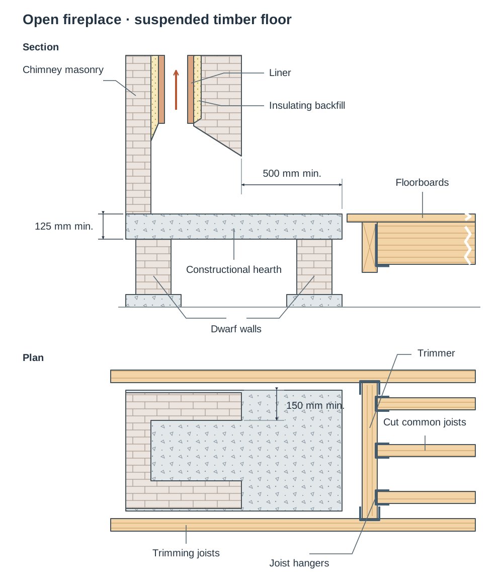
- Concrete constructional hearth: non-combustible slab at least 125 mm thick, resting on solid dwarf masonry walls (fender walls); for an open fireplace, it must extend at least 500 mm in front of the fireplace jambs and at least 150 mm beyond each side of the fireplace opening.
- Superimposed (decorative) hearth: non-combustible layer at least 48 mm thick extending at least 300 mm in front and 150 mm each side of a closed appliance.
- Timber joist trimming: trimmer joists carried on joist hangers built into trimming joists. Combustible timber must maintain a minimum clearance of 200 mm from the inside surface of the flue liner, and at least 40 mm from the outer face of chimney masonry or fireplace recess. Metal fixings must stay at least 50 mm from the internal flue surface.
- Fireplace throat unit and gather: narrows opening to 100 mm to accelerate gases and prevent room smoke spillage.
- Flue liner: clay, pumice, or stainless steel (min 200 mm diameter for open fires; 150 mm for stoves) laid with socket ends facing upwards to retain acidic condensate inside the liner.
- Insulating backfill: lightweight vermiculite/lime mix filling the gap between liner and brick chimney to preserve flue gas heat and draught.
- Termination: chimney pot bedded in flaunching terminating at least 600 mm above the roof ridge to eliminate wind downdraughts.
- Combustion air vent: permanently open external wall vent (or direct supply duct to the appliance in airtight homes). For an open fire with a throat, provide a free area of at least 50% of the cross-sectional area of the throat; for a closed solid-fuel appliance, provide at least 550 mm² free area per kW of rated output above 5 kW to prevent room oxygen depletion.
- Solid-fuel safety fittings: an unvalved gravity-fed heat leak radiator to dump surplus heat during power cuts, an open vent pipe, and a carbon monoxide alarm mounted on the ceiling 1–3 m horizontally from the appliance.
Heat Loss, Running Costs, and Payback Calculations
At Higher Level, space heating calculations demand fabric loss, ventilation loss, gross fuel input, and payback analysis.
Core Calculation Formulas
- Fabric Heat Loss Rate ():
where is thermal transmittance (), is surface area (), and is the difference between internal and external design temperatures (). Use the design outside temperature (typically −1 °C to −3 °C) when sizing boilers, and the mean seasonal temperature (e.g., 4 °C) when calculating annual running costs.
- Ventilation Heat Loss Rate ():
where 0.33 is the volumetric heat capacity of air (), is air changes per hour (), is internal room volume (), and is temperature difference ().
- Total Heat Loss Rate ():
- Net Annual Energy Demand ():
- Gross Fuel Energy Input ():
Divide net energy by boiler seasonal efficiency ():
- Simple Payback Period:
Key terms
- Calorifier
- A storage vessel in which domestic secondary water is heated indirectly by hot water circulating through an internal primary coil.
- Primary heat exchanger (heating coil)
- The coiled copper pipe fitted inside an indirect cylinder through which primary boiler water circulates to heat domestic secondary water by conduction.
- Feed and expansion cistern
- A 45-litre attic header tank that keeps the primary heating circuit topped up with water and provides expansion volume when the circuit heats up.
- Open safety vent pipe
- An unvalved pipe rising from the flow side of a water circuit that turns down over an attic cistern to release steam and expanding water safely if overheating occurs.
- Stratification
- The natural thermal layering of water inside a cylinder, where hotter, less dense water stays at the top while incoming cold water rests at the bottom.
- Unvented cylinder
- A sealed domestic hot water storage vessel connected straight to the cold mains supply, doing away with attic cisterns and relying on mechanical relief valves.
- Expansion vessel
- A sealed steel container holding an internal rubber diaphragm and nitrogen gas cushion that compresses to take up expanding water volume in closed systems.
- Two-pipe system
- A space heating layout where each radiator is connected in parallel between separate flow and return pipes, supplying equal water temperatures to all emitters.
- Lockshield valve
- A capped radiator valve adjusted with a spanner during commissioning to regulate water resistance and balance flow across all radiators.
- Thermostatic radiator valve (TRV)
- A self-operating valve fitted to a radiator inlet that expands or contracts an internal capsule to throttle hot water flow as room air warms.
- Boiler interlock
- An electrical control wiring system that shuts down both burner and circulating pump when all room and cylinder thermostats are satisfied.
- Heat leak radiator
- An unvalved, gravity-circulated radiator installed on a solid-fuel boiler circuit to safely dump excess heat if the pump stops or zone valves close.
- Constructional hearth
- A solid, non-combustible concrete slab at least 125 mm thick built beneath a fireplace or stove to form a fireproof barrier over timber floors.
- Trimmer joist
- A cross timber joist supported by trimming joists on either side of a fireplace opening to carry the ends of cut common joists clear of chimney masonry.
- Seasonal efficiency
- The ratio of useful heat energy supplied to a building across an entire heating season divided by the total gross calorific energy of the fuel consumed.
- Coefficient of performance (COP)
- The ratio of useful thermal energy output delivered by a heat pump divided by the electrical energy input needed to drive the compressor.
- Tundish
- A plumbing fitting with an open air gap installed in safety relief discharge pipework to give a visual warning of water release while preventing back-siphonage.
- Motorised zone valve
- An electrically driven two-port valve controlled by a thermostat or programmer that directs primary water flow to separate heating or hot water circuits.
Check yourself
Why is the kitchen sink the only tap connected directly to the rising main in an indirect cold water system?
Water from the rising main is fresh and unstored, ensuring clean drinking quality. Stored cistern water in the attic may pick up airborne dust, insect contamination, or warm up in summer.
A bedroom measures 4.0 m × 3.0 m × 2.4 m high and has an air infiltration rate of 0.75 air changes per hour. If the room is heated to 18 °C when outside is 2 °C, calculate the ventilation heat loss rate in watts.
114.05 W. (Volume = 4.0 × 3.0 × 2.4 = 28.8 m³; ΔT = 18 − 2 = 16 K; Qv = 0.33 × 0.75 × 28.8 × 16 = 114.048 W).
Why must domestic hot water be stored at 60–65 °C, and how are occupants protected from scalding at the bath?
Storing hot water at 60–65 °C kills Legionella bacteria. A thermostatic mixing valve is fitted near the bath outlet to blend hot and cold water down to a safe delivery temperature of roughly 46–48 °C.
Why is a sealed (pressurised) heating circuit forbidden from connecting to a standard solid-fuel stove with a back boiler?
A solid-fuel fire cannot be shut down instantly by a thermostat. If the circulating pump fails or power cuts out, heat continues building, creating dangerous over-pressurisation that requires an open vent pipe to relieve safely.
What is the primary advantage of a two-pipe heating system over a one-pipe ring system?
A two-pipe system supplies primary hot water to all radiators in parallel at the same initial boiler design temperature, whereas a one-pipe system suffers progressive temperature drops along the loop.