

A house loses heat through its roof, walls, floor, windows and draughts. This topic shows you how heat escapes, how to calculate it (U-values and the yearly cost of heat loss), and how insulation, good detailing and ventilation keep a house warm, dry and healthy.
Heat Transfer Fundamentals, Fabric Loss, and Thermal Comfort
Heat always flows from a warmer place to a colder place. In winter, that means from inside the house to outside. Heat moves through the building envelope by three mechanisms:
- Conduction: Heat transfer through solid materials by particle vibration, such as heat passing through concrete blocks, timber framing, or metal lintels.
- Convection: Heat transfer through the circulation of liquids or gases, such as warm air rising in an open wall cavity or air currents tumbling down a cold windowpane.
- Radiation: Heat transfer across open space by electromagnetic waves without heating the air in between, such as heat radiating from a stove or sunlight streaming through south-facing glass.
In an older, uninsulated house, heat escapes in these approximate typical proportions:
- External walls: ~35%
- Roof and attic: ~25%
- Ground floor: ~15%
- Draughts and ventilation: ~15%
- Windows and external doors: ~10%
Thermal Comfort and Radiant Temperature
Comfort indoors involves more than air temperature alone. Mean radiant temperature is the average temperature of the surfaces surrounding a person, including walls, windows, floor, and ceiling. Because the human body radiates heat directly to colder surroundings, a room with warm air can still feel chilly if the walls or glazing are cold. Well-insulated walls raise interior surface temperatures, giving much better comfort at the same air temperature.
Thermal comfort depends on five key factors:
- Air (dry bulb) temperature (typically 18 °C to 21 °C in living areas)
- Mean radiant temperature of surrounding surfaces
- Relative humidity (ideally 40% to 60%)
- Air movement (draughts cause chills, but fresh air prevents stuffiness)
- The occupant's activity level and clothing
Thermal Properties, U-Values, and Temperature Gradients
Calculating how a structural element resists heat flow relies on four core thermal measurements:
- Thermal conductivity (-value): The rate of heat flow through a 1 m thickness of a material per degree temperature difference across its faces, measured in or . Dense materials have high values (concrete block is about ), while good insulators have very low values (PIR board is about ).
- Thermal resistivity (-value): The resistance to heat flow of one metre thickness of a material, per metre squared (, measured in or ). Some exam questions supply instead of for plasters and screeds.
- Thermal resistance (-value): The actual resistance provided by a specific material layer of thickness in metres:
For example, 100 mm of mineral wool with gives:
Boundary layers of still air clinging to building surfaces also resist heat flow. These are the internal surface resistance () and external surface resistance (). Any unventilated air cavity provides a cavity resistance (). Note that a ground-floor slab cast on subsoil has an internal surface resistance () but no external surface resistance ().
- Thermal transmittance (-value): The rate of heat loss through one square metre of a complete structural element per degree temperature difference between inside and outside:
Measured in , a lower U-value means better thermal performance.
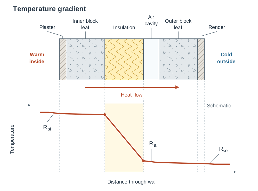
Temperature Gradients Through a Wall
The temperature drop across any individual layer is directly proportional to its share of the total thermal resistance:
To plot a gradient:
- Calculate the total resistance () and overall temperature difference ().
- Start at the indoor air temperature.
- Subtract the temperature drop across , then subtract the drop across each layer in turn, moving outwards to the cold face.
Because high-performance insulation contributes the vast majority of the total resistance, almost the entire temperature drop occurs inside that insulation layer. The cold outer face of the insulation is where temperatures plummet, showing why indoor water vapour must be stopped before it can reach this cold zone.
Steady-State Heat Loss, Ventilation Loss, and Annual Fuel Costs
Heat loss through the building fabric is calculated under steady-state conditions using:
where is the heat loss rate in Watts (Joules per second), is the exposed surface area in , and is the temperature difference across the element. For walls and roofs, . For ground floors, .
Ventilation Heat Loss
Heat is also carried away when warm indoor air escapes and is replaced by cold outdoor air:
where is the ventilation rate in air changes per hour (ACH), is the room volume in , and is the volumetric heat capacity of air. For a living room of with and , ventilation heat loss is:
Total building heat loss equals total fabric loss plus total ventilation loss.
Five-Step Space-Heating Cost Method
To calculate the annual running cost of replacing fabric heat loss:
- Calculate heat loss rate (): Find in Watts ().
- Calculate total heating time () in seconds:
- Calculate total energy lost in kilojoules (kJ):
- Calculate fuel quantity consumed: Divide total energy lost by fuel calorific value (oil is typically ; wood pellets are typically ):
- Calculate annual cost: Multiply fuel quantity by the unit price (€).
Costs-in-Use, Payback, Statutory Standards, and Heat Gains
Costs-in-use means evaluating a building element over its entire working life: initial purchase and installation costs plus annual space-heating running costs.
Payback Period
The payback period is the time in years required for heating cost savings to repay the capital cost of an insulation upgrade:
If upgrading an uninsulated external wall costs €4,200 and reduces the annual oil bill from €352 to €96, the annual saving is €256. The payback period is . If fuel prices rise over time, the annual financial saving increases, which shortens the payback period.
Statutory Thermal Transmittance Values
Technical Guidance Document L (TGD Part L: Conservation of Fuel and Energy – Dwellings) sets mandatory maximum U-values for new dwellings:
- External walls:
- Ground floors:
- Pitched roof (insulated at ceiling or rafters):
- Flat roof:
- External windows, doors, and rooflights:
By comparison, the voluntary Passive House standard demands a much stricter wall U-value of or lower. To check compliance in an exam question, compare your calculated U-value against the statutory maximum: the element complies only if its U-value is equal to or lower than the regulation figure.
Internal and Solar Heat Gains
A house gains heat from internal and external sources, reducing the net heat the boiler or heat pump must supply:
- Solar heat gain: Short-wave solar radiation passes through glazing and is absorbed by high thermal mass elements like concrete floors and plastered masonry, which slowly re-radiate warmth into the room. Gains are highest through large south-facing windows.
- Internal gains: Heat released inside the dwelling by occupants (roughly 80 W to 100 W per person), electric lighting, cooking, and household appliances.
Insulation Materials, High-Void Structures, and Retrofit Techniques
High-void insulating materials consist of small, motionless pockets of air or blowing gas enclosed within lightweight cellular or fibrous structures. Because still air is an exceptionally poor conductor of heat and tiny pockets prevent air from circulating by convection, heat transfer is severely suppressed. Common high-void materials include mineral wool, expanded polystyrene, and cellulose. If these materials become wet on site, their performance collapses because liquid water conducts heat roughly 25 times faster than still air.
Reflective insulating materials (such as aluminium foil facings and multi-foil membranes) work differently. Their shiny, low-emissivity surface reflects radiant heat back towards the warm side and gives off very little radiation itself. They only work when they face a still air gap, because touching a solid surface lets heat conduct straight through.
| Material | Typical -value () | Typical Application |
|---|---|---|
| Mineral Wool (Rock/Glass) | 0.035 – 0.040 | Loft quilts, timber-frame studs, acoustic partitions |
| Expanded Polystyrene (EPS) | 0.031 – 0.037 | External wall insulation (EWI), floor slab insulation |
| Extruded Polystyrene (XPS) | 0.028 – 0.034 | Heavy-load ground floors, foundation perimeter edges |
| Polyisocyanurate (PIR) | 0.022 – 0.026 | Partial-fill cavity walls, cut-rafter warm roofs |
| Cellulose Fibre | 0.038 – 0.040 | Blown attic insulation, timber-frame cassettes |
| Reflective Foil Barriers | Variable | Cavity membranes (requires adjacent still air gap) |
Retrofitting Existing External Walls
- Cavity Bead Injection: Pumping EPS beads bonded with an adhesive emulsion through holes drilled in outer mortar joints. Ideal for uninsulated cavity walls without disturbing interior finishes.
- External Wall Insulation (EWI): Fixing rigid insulation (EPS or mineral wool) to the outside face of masonry in five ordered steps: (a) mechanically fix an aluminium base starter track at DPC level; (b) bond and mechanically anchor insulation boards tightly to the wall; (c) apply a cementitious base coat render; (d) embed an alkali-resistant glass-fibre mesh into the wet base coat; (e) apply an external primer followed by a weatherproof, breathable polymer finish.
- Internal Dry-Lining: Fixing composite insulated plasterboard to the inside wall face with adhesive dabs or timber battens. It keeps the external facade unaltered, but slightly reduces internal room area and requires careful sealing around sockets and joists.
Thermal Bridging, Detailing, and Thermal Looping
A thermal bridge (or cold bridge) happens where a material with higher thermal conductivity penetrates the insulation, or where the insulation layer is broken. Typical locations include concrete window lintels, window sills and jambs, junctions between ground-floor slabs and external walls, and eaves junctions.
Thermal bridges can account for a significant share of fabric heat loss in an otherwise well-insulated house. They also create cold interior surface spots, causing surface condensation and mould growth, which damages finishes and can aggravate asthma and other respiratory problems.
Detailing the Wall-to-Floor Junction
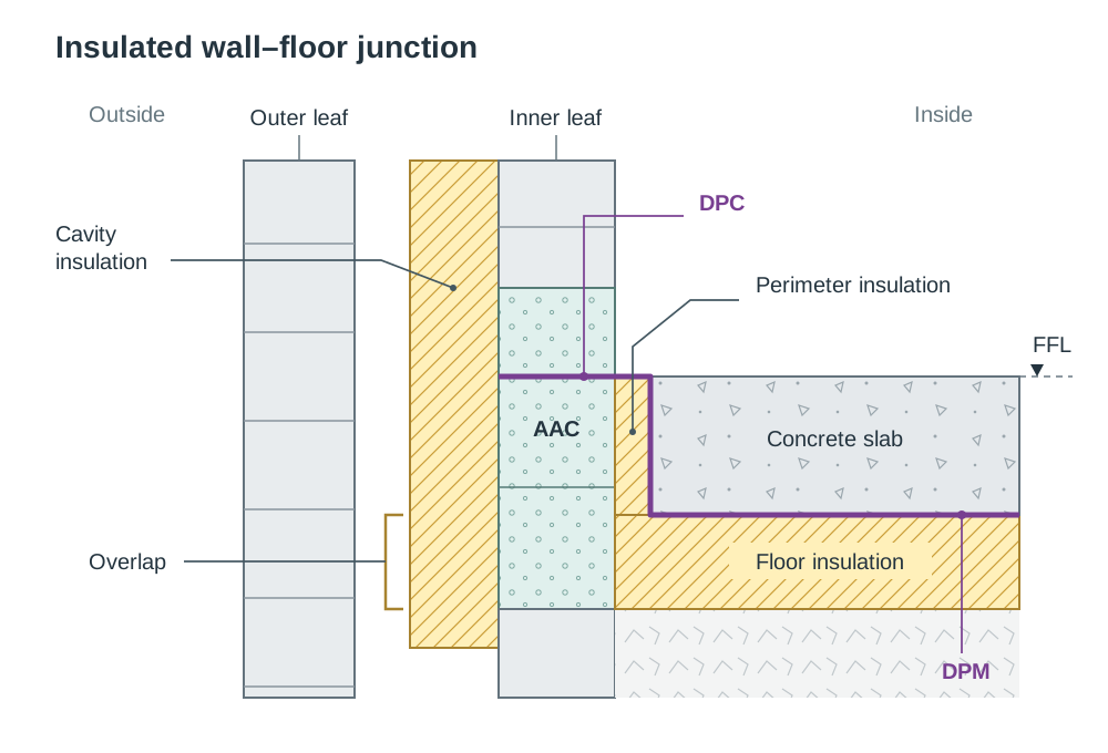
To eliminate thermal bridging where a ground floor meets an external cavity wall, assemble the junction in these ordered steps:
- Lay autoclaved aerated concrete (AAC) thermal-break blocks in the inner leaf at and below finished floor level to slow downward conduction.
- Continue the cavity wall insulation down below finished floor level, so that it overlaps the perimeter edge insulation and the floor insulation and leaves no uninsulated gap at the junction.
- Install a continuous layer of rigid sub-floor insulation horizontally beneath the concrete floor slab or screed.
- Fit vertical perimeter edge insulation (minimum 25 mm thick) between the edge of the floor slab and the inner block leaf, ensuring it laps tightly against the sub-floor insulation.
- Dress the damp proof membrane (DPM) under the slab up and over the perimeter insulation, linking seamlessly with the wall damp proof course (DPC).
Attic Insulation Detailing
When insulating an attic floor with mineral wool, roll the first layer between the ceiling joists to the joist depth. Then lay the second layer perpendicular (at right angles) across the joists. This cross-laying covers the timber joists, eliminating thermal bridging through the wood and sealing any gaps between the first-layer batts.
Thermal Looping
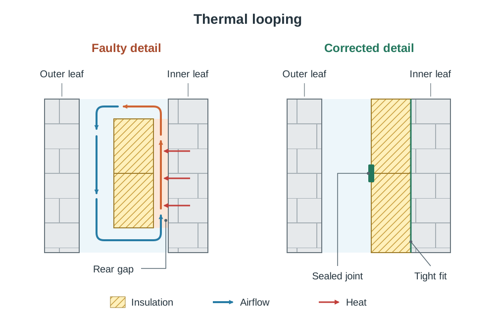
Thermal looping occurs when an unsealed air gap is left between the inner masonry leaf and cavity insulation boards. Cold air enters at the base of the cavity, absorbs heat escaping from the inner leaf, warms up, rises by convection, and spills over the top of the insulation into the cold outer air space. This continuous convective loop pulls heat straight out of the inner masonry leaf, which can seriously reduce the insulation's actual performance. It is prevented by bedding boards tightly against smooth blockwork and taping or tongue-and-grooving all board edges.
Moisture, Psychrometry, Condensation, and MVHR
Air holds invisible water vapour, and warm air can hold far more moisture than cold air.
- Dry bulb temperature: Ambient air temperature measured by an ordinary shielded thermometer.
- Wet bulb temperature: Temperature measured by a thermometer whose bulb is wrapped in a damp fabric wick cooled by evaporating water. The drier the room air, the faster water evaporates, causing a greater difference between wet bulb and dry bulb readings.
- Relative humidity (RH): The ratio of actual moisture present in air compared to the maximum moisture it could hold at that temperature, expressed as a percentage.
- Dew point: The critical temperature at which air reaches 100% saturation. Any further cooling forces excess vapour to condense into liquid water.
Reading the Psychrometric Chart
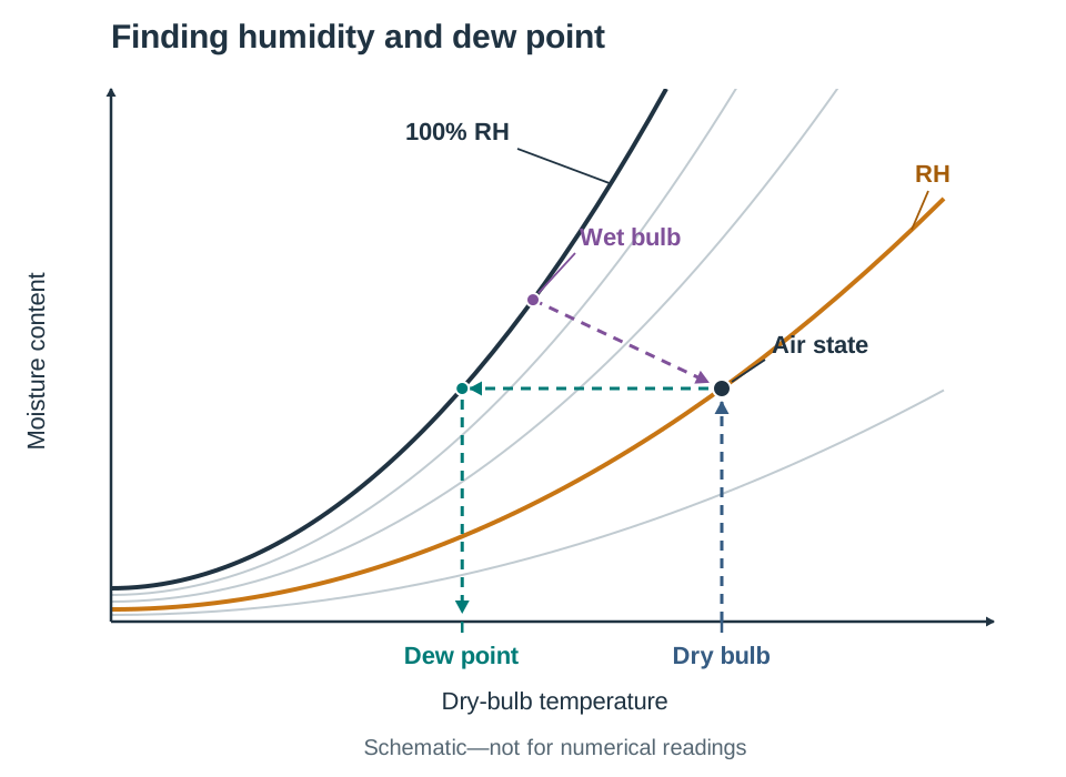
To find relative humidity and dew point:
- Measure dry bulb and wet bulb temperatures using a whirling (sling) hygrometer.
- Locate the dry bulb temperature on the horizontal bottom axis and draw a vertical line upwards.
- Locate the wet bulb temperature on the outer curved saturation line and follow the diagonal wet-bulb line down to intersect the vertical dry-bulb line.
- Read the relative humidity from the curved percentage line passing through that intersection point.
- From that intersection point, move horizontally left to the outer saturation curve (100% RH). The temperature read there is the dew point.
Condensation Mechanisms and Mould
- Surface condensation: Warm, moist room air contacts a surface colder than the dew point of that air (such as single glazing or an uninsulated lintel), causing droplets to form on the surface.
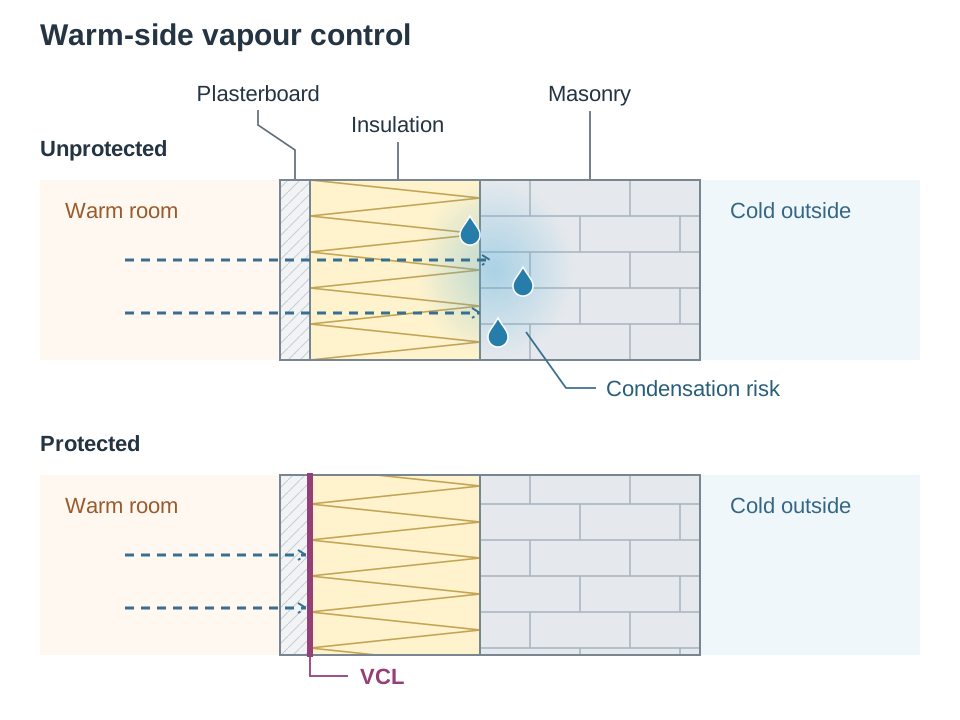
- Interstitial condensation: Water vapour diffuses outward through plasterboard and insulation into the structural layers of a wall or roof. As it encounters colder outer zones, it reaches its dew point and condenses invisibly inside the construction, saturating insulation, rotting timber, and corroding wall ties.
To prevent interstitial condensation, install a continuous vapour control layer (VCL), such as 500-gauge polythene or foil backing, strictly on the warm indoor side of the insulation. This stops moisture before it can reach the cold outer structure.
Mould spores germinate on organic building surfaces (plasterboard paper, timber, wallpaper) when the surface relative humidity remains at or above 70% for sustained periods.
Mechanical Ventilation with Heat Recovery (MVHR)
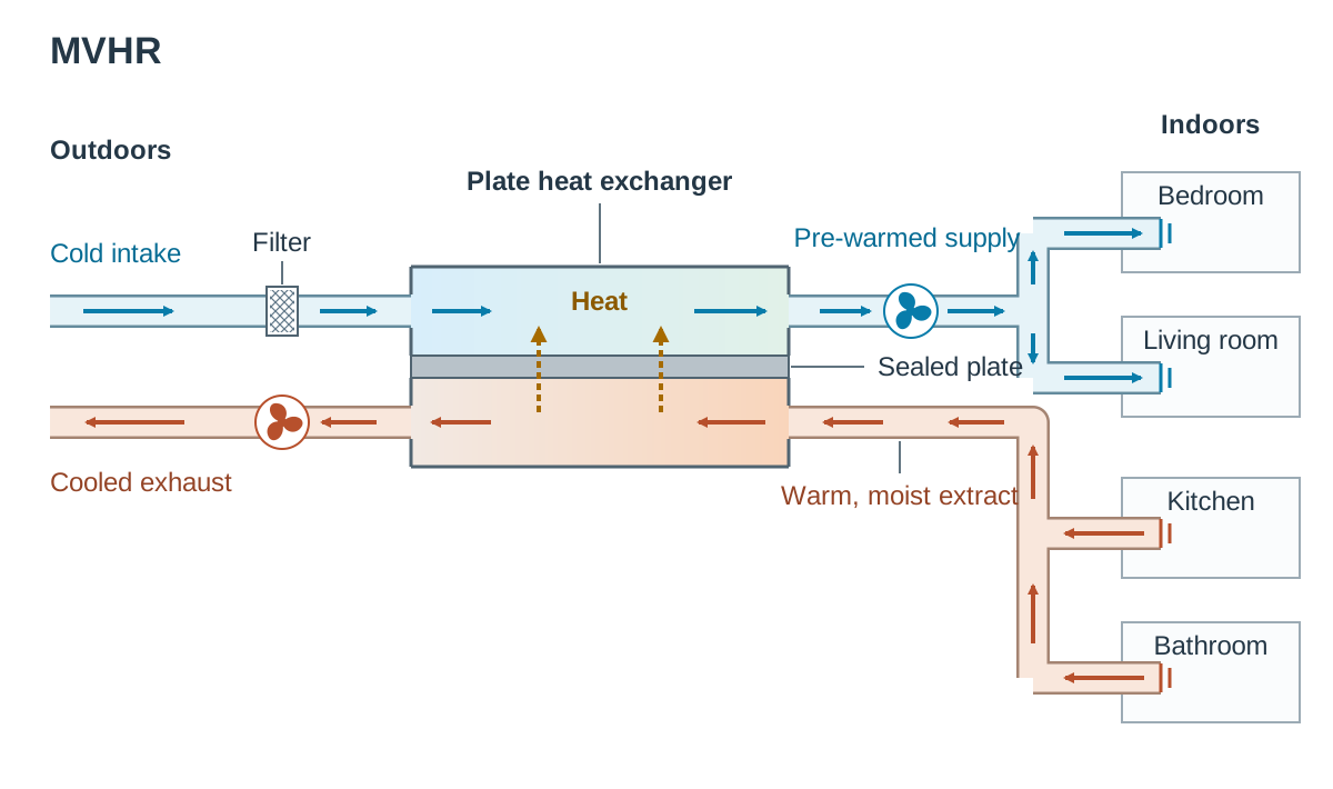
In an airtight house, natural ventilation is weather-dependent: strong winds cause over-ventilation and heat loss, while calm humid days lead to under-ventilation and condensation. An MVHR system provides balanced, controlled air exchange:
- Warm, moist air is continuously extracted through ducted ceiling terminals from wet rooms (kitchens, utility rooms, bathrooms).
- Fresh outdoor air is drawn into the building through a separate external intake duct.
- Both air streams pass simultaneously through a central counter-flow plate heat exchanger where outgoing heat conducts across thin plates into the incoming fresh air, without the two air paths ever mixing.
- Incoming fresh air is filtered to remove dust, pollen, and airborne particles before entering the rooms.
- Pre-warmed, clean fresh air is ducted continuously into habitable rooms (bedrooms and living areas).
Two principal advantages of MVHR are:
- Energy efficiency: It recovers up to 90% of heat that would otherwise be exhausted, substantially reducing space-heating demand.
- Indoor air quality: It provides continuous, draught-free fresh air, eliminates condensation and mould risks, and filters outdoor allergens.
Key terms
- Thermal Conductivity (k-value)
- The rate of heat flow through one metre thickness of a material per degree temperature difference across its faces, measured in W/m°C or W/m K.
- Thermal Resistivity (r-value)
- The opposition to heat flow of one metre thickness of a material per metre squared (r = 1/k), measured in m°C/W.
- Thermal Resistance (R-value)
- The opposition to heat flow provided by a specific material layer of thickness T in metres (R = T/k or R = T × r), measured in m²°C/W.
- Thermal Transmittance (U-value)
- The overall rate of heat loss through one square metre of a complete structural element per degree temperature difference between indoor and outdoor environments (U = 1/Rt), measured in W/m²°C.
- Thermal Bridge
- A break in insulation continuity or a path of high thermal conductivity through the building envelope, causing localized heat loss, cold spots, and surface condensation.
- Thermal Looping
- Convective air movement in an unsealed gap between an inner masonry leaf and cavity insulation, drawing heat directly out of the wall and degrading insulation performance.
- Dew Point
- The temperature to which air must cool for its relative humidity to reach 100%, causing water vapour to condense into liquid water droplets.
- Interstitial Condensation
- Condensation that forms invisibly inside the internal structural layers of a wall, floor, or roof when outward-diffusing water vapour cools below its dew point.
- Vapour Control Layer (VCL)
- An impermeable membrane (such as 500-gauge polythene) positioned strictly on the warm indoor side of insulation to stop vapour entering the structural fabric.
- Mechanical Ventilation with Heat Recovery (MVHR)
- A balanced mechanical system that extracts warm, stale air from wet rooms and transfers its heat across a plate exchanger to pre-warm incoming fresh air supplied to living spaces.
- Costs-in-Use
- The assessment of a building component based on its full life-cycle cost, combining initial purchase and installation expenses with ongoing annual heating and maintenance costs.
- Payback Period
- The time in years required for the cumulative annual financial savings on space heating to equal the initial capital cost of an insulation upgrade.
Check yourself
What is the thermal resistance of a 150 mm layer of mineral wool with a conductivity of k = 0.038 W/m°C?
R = T / k = 0.150 / 0.038 = 3.947 m²°C/W.
An uninsulated roof costs €480 per year in heating oil. After adding loft insulation costing €1,200, the annual oil cost drops to €80. What is the payback period?
Annual saving = 480 - 80 = €400/year. Payback period = €1,200 / €400 = 3 years.
Why must mineral wool insulation in an attic be cross-laid in two perpendicular layers?
The first layer fills the space between joists, and the second layer laid across them covers the timber, eliminating thermal bridging through the joists and sealing any gaps between batts.
Why must cavity wall insulation boards be fitted tightly against the inner block leaf?
To eliminate gaps behind the boards, preventing thermal looping where convective air currents circulate behind the insulation and draw heat directly out of the inner leaf.
How do you find the dew point of room air using a psychrometric chart?
Plot the intersection of the vertical dry-bulb line and the sloping wet-bulb line, then move horizontally left to the 100% saturation curve to read the dew point temperature.