

Foundations form the structural substructure of a building, acting as the critical link that safely transmits all dead, imposed, and lateral wind loads into the ground without exceeding the soil's safe bearing capacity. For Leaving Certificate Construction Studies Higher Level, students must master the functional requirements of foundations, subsoil hazards, site investigation techniques, the geometry and sizing of strip and stepped footings, pad foundations, short-bored piles, raft foundations (including the examined passive raft), excavation safety, water management, and concrete batching and placement practices.
Functional Requirements and Structural Principles
A foundation is the lowest structural element of a building. It must satisfy five key functional requirements:
- Load distribution: Safely transmit the dead load (permanent self-weight of building components) and imposed load (occupants, furniture, snow) into the earth so that the safe bearing capacity of the soil is never exceeded.
- Stability and anchorage: Anchor the superstructure against overturning, sliding, and uplift caused by wind and lateral soil pressures.
- Level platform: Provide a flat, true, horizontal base from which rising masonry, timber frame, or concrete construction can proceed.
- Limit differential settlement: Minimise uneven downward movement between different parts of the building to prevent racking of frames and diagonal shear cracking in walls.
- Resist subsoil movement: Withstand seasonal ground pressures, including swelling and shrinkage in cohesive soils and frost heave.
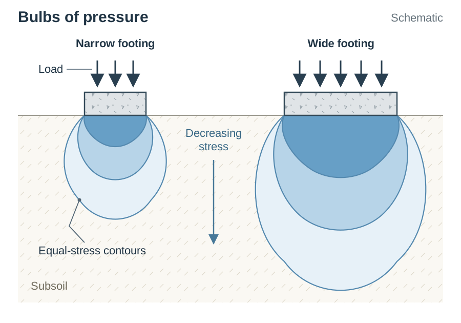
When a footing transfers vertical load down to the subsoil, stress radiates downward and outward in curved contours of equal stress known as the bulb of pressure. High-intensity stress concentrates directly beneath the footing and dissipates with depth. A narrow footing creates a shallow, concentrated bulb of pressure. A wider foundation produces a deeper, broader pressure bulb. If adjacent stress bulbs overlap, or if a bulb extends into a weak, compressible subsoil layer, excessive settlement will occur.
Pad Foundation Sizing
An isolated pad foundation spreads a concentrated point load from a steel stanchion, precast column, or masonry pier over an adequate area of subsoil. The required plan area is calculated using the safe bearing capacity:
For example, if a porch column delivers a vertical load of onto firm gravelly clay with a safe bearing capacity of :
A square pad requires a side length of . A reinforced concrete pad footing satisfies this requirement.
Site Investigation, Subsoil Movement, and Ground Hazards
A thorough site investigation must take place before foundation design starts. This establishes the depth to firm bearing strata, the level of the water table, the presence of shrinkable clay or made-up ground (fill), and radon risk from the EPA radon map.
Site Investigation Methods
- Desk study: Review historical Ordnance Survey maps, geological surveys, local authority flood records, and previous planning records for the area.
- Walk-over survey: Inspect the site for surface water, tell-tale wetland vegetation (rushes, willows), topography, and existing cracks in adjacent buildings or boundary walls.
- Trial pits: Excavate open pits with a mechanical digger to a depth of to . This allows direct visual inspection of soil strata, soil sampling, and measurement of the resting water table.
- Boreholes: Bored deep into the ground using mechanical drilling rigs to recover core samples where rock or firm strata lie well below normal trench depth.
Settlement versus Subsidence
- Settlement: The downward movement of a building caused by the consolidation of subsoil under the building's own self-weight. Uniform settlement occurs at an even rate across the whole building and rarely causes structural distress. Differential settlement occurs when separate parts of the structure sink unevenly due to varying soil strata or uneven loads, inducing high shear stresses and stepped diagonal cracks in walls.
- Subsidence: Ground movement beneath the footings caused by external factors independent of building load. Typical causes include leaking underground water mains washing away soil fines, falling groundwater tables, or mining cavities.
Ground Hazards
- Frost heave: Freezing of moisture in upper soil layers causes water to expand by roughly 9%, forming ice lenses that lift shallow footings. To avoid frost heave in Ireland, the underside of foundations must be taken down to firm ground at least 600 mm below finished ground level.
- Shrinkable clay and trees: Cohesive clay soils shrink significantly during dry weather as tree roots extract soil water. If a mature tree is felled, the desiccated soil slowly re-absorbs rainwater and expands upward over several seasons. This upward pressure, called ground heave, fractures rising walls. Keep foundations clear of trees by a distance at least equal to the mature height of the tree, or carry footings down below the root zone.
- Pyritic heave: Hardcore beneath ground slabs that contains the mineral iron pyrite () oxidises in the presence of moisture and air, producing sulphuric acid which reacts with calcium carbonates to form expansive crystals. This chemical expansion heaves the concrete floor slab upward, lifting internal stud partitions and cracking external masonry.
Foundation Types and Selection Criteria
The choice of foundation depends on soil bearing capacity, the depth of stable strata, building loads, and the site topography.
| Foundation Type | Typical Ground and Site Conditions | Key Construction Features |
|---|---|---|
| Traditional Strip | Firm, uniform subsoil (compact gravel, stiff boulder clay) with standard domestic wall loadings. | Continuous mass or reinforced concrete strip under all load-bearing walls. Underside at least 600 mm below finished ground. |
| Stepped Strip | Sloping sites where following the natural ground slope minimises excavation and deep rising walls. | Footing steps along the slope in multiples of block course heights (). Laps horizontally where levels change. |
| Wide Strip | Low-bearing soils (soft clay, sand-silt mixes) where wall loads must be spread broadly. | Wider footing fitted with transverse steel rebar in the bottom tensile zone to stop the projecting concrete wings cracking upward. |
| Deep Strip (Trench Fill) | Firm bearing ground lying to below surface level. | Trench is filled with mass concrete to within of ground level, cutting out hazardous bricklaying inside deep, narrow trenches. |
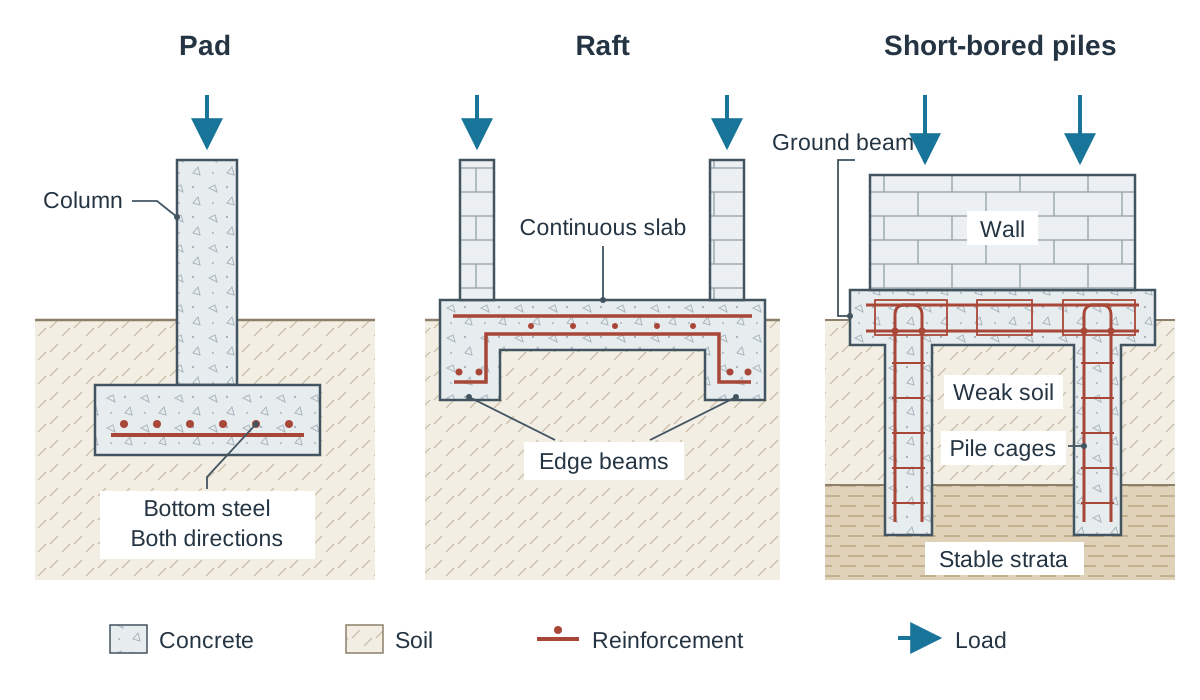
| Pad Foundation | Framed structures where loads arrive as concentrated point loads from columns or piers. | Isolated reinforced concrete blocks with steel placed in both directions near the bottom. Linked by a ground beam if carrying walls. |
| Raft Foundation | Soft, compressible, or variable ground (reclaimed land, peat margins, soft clays). | A continuous reinforced concrete slab covering the whole building footprint with stiffened downstand edge beams, moving as one rigid unit. |
| Short-Bored Piles | Shrinkable clay or poor surface fill with stable strata within of ground level. | Bored vertical shafts filled with concrete and steel rebar cages, tied together at ground level by a continuous reinforced ground beam. |
Traditional Strip versus Passive Raft
Higher Level questions (e.g. 2022 Q4(c)) have asked you to compare a traditional strip with a passive raft foundation:
- Traditional Strip: Familiar, economical craft method using standard site skills. However, it requires deep trench excavations, extensive blockwork in rising walls, has high embodied energy due to concrete volume, and produces a major cold bridge at the wall-to-floor junction.
- Passive Raft: The structural slab sits directly inside a continuous cradle of high-density expanded polystyrene (EPS) insulation. This eliminates the wall-to-floor thermal bridge completely and delivers an airtight, fast sub-floor platform with reduced excavation depth. The trade-offs are higher initial material costs, the need for an engineered design, and specialist, certified site installation.
Design Geometry and Sizing for Strip Foundations
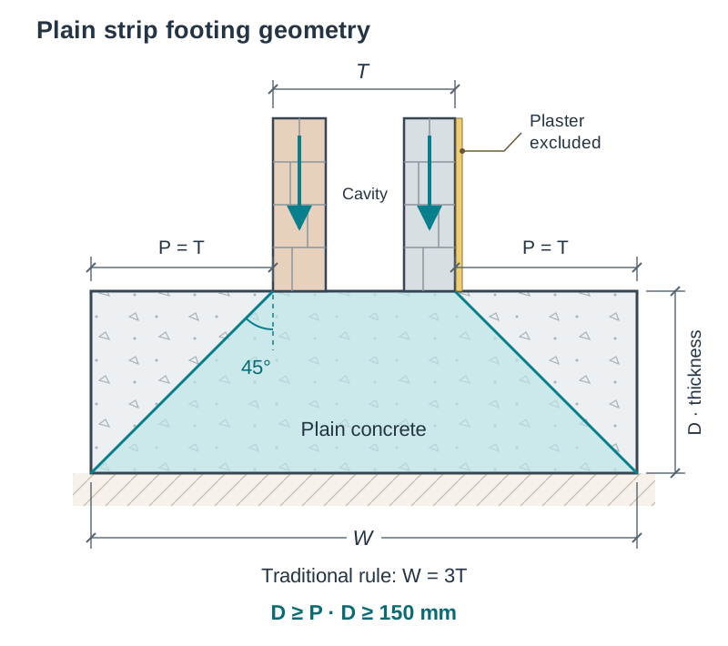
In an unreinforced concrete strip foundation, structural wall loads disperse downward through the footing at a angle of spread. Sizing must ensure the concrete stays in pure compression without developing tension in the outer projections.
Traditional Sizing Rules
- Structural wall thickness (): The overall width of the masonry wall, from the outer face of the outer leaf to the inner face of the inner leaf (leaves plus cavity). This is the footprint whose edges set where the load spread starts. Internal gypsum plaster () is excluded because it is a thin applied finish, not part of the masonry sitting on the footing.
- Width (): A traditional rule of thumb for plain concrete strips is , which provides an equal projection on each side of the wall.
- Depth/Thickness (): Under Building Regulations Technical Guidance Document A (TGD A), the depth of a plain concrete footing must be at least equal to its projection () and never less than . When , the projection , meaning .
If a plain concrete footing is made wider without increasing its depth or introducing steel reinforcement, the projection exceeds the depth (). Soil reaction forces bend the outer wings upward, inducing tensile stresses in the bottom face that cause diagonal shear cracks along the plane.
Stepped Foundation Rules
When constructing strip foundations on sloping ground:
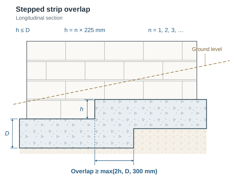
- The vertical step height () must not exceed the foundation depth () and must equal an exact multiple of the block course height ( for a standard block with a mortar bed).
- The horizontal overlap of the upper footing over the lower footing must equal twice the step height (), the foundation thickness (), or , whichever is greatest.
Excavation Safety and Water Management
Foundation excavations present severe safety and structural risks that must be managed on site.
Trench Safety
- Support trench sides exceeding in depth, or in wet, loose soil, using pre-assembled steel trench boxes or timber shoring (poling boards, walings, and adjustable steel trench struts). Alternatively, batter the sides back to a safe angle of repose.
- Keep spoil heaps and heavy machinery at least back from the trench lip. Surcharge (weight placed near the edge) causes sudden sidewall collapse.
- Install continuous safety barriers and warning signage around open excavations, provide secure ladder access points, locate all underground utility services before digging, and never enter an unsupported trench.
Problem of Water in Excavations
Water enters trenches from rain, surface run-off, high water tables, natural springs, or broken drains. If left unmanaged, standing water softens the trench bed and reduces the soil's bearing capacity, causes trench walls to collapse, and washes cement paste out of fresh concrete, leaving honeycombed, weak footings.
Dewatering and site remedies:
- Dig trenches in dry conditions and pour concrete promptly following building control or structural inspection.
- Cut off surface run-off by excavating an uphill cut-off (French) drain lined with geotextile and backfilled with clean drainage stone.
- Form a sump (a small collection pit) at the lowest point of the excavation, outside the structural footing line, and continuously pump water away using a submersible pump.
- Where the water table is high throughout the site, lower it before excavation begins using wellpoint dewatering (perforated pipes jetted into the ground and coupled to a vacuum header pipe).
- Remove any softened, contaminated mud from the trench bottom, then place a blinding layer of lean-mix concrete before setting steel or pouring structural concrete.
Site Setting Out, Reinforcement, and Concreting Practice
Foundation installation follows an ordered, verified site sequence:
- Site clearance: Strip vegetable topsoil (typically to deep) from the building footprint. Topsoil contains decaying organic matter that compresses under load and must never support foundations.
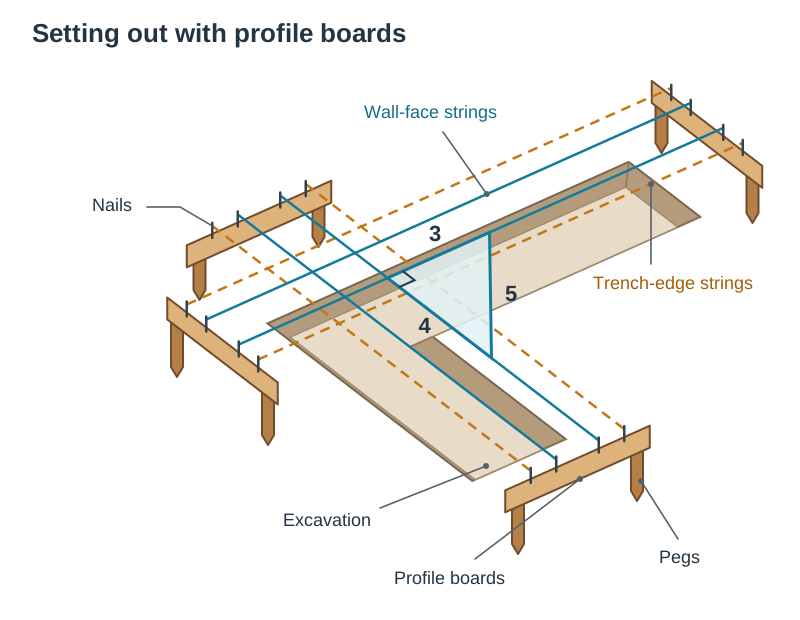
- Setting out with profile boards: Establish the front building line from the approved site plan, measuring from the road or site boundary. Use a site benchmark to set levels. Lay out perpendicular corners using an optical site square or the 3:4:5 right-angled triangle method. Erect timber profile boards well back from the dig line to prevent plant disturbance. Cut saw kerfs or drive nails into the boards to hold the string lines that mark trench excavation widths and wall leaf faces.
- Trench preparation and blinding: Dig trenches down to firm, undisturbed subsoil below frost depth (minimum 600 mm). Compact and level the base, then lay a blinding layer of lean-mix concrete (C10 mix). Blinding seals the ground, stops moisture being drawn out of the structural pour, and provides a clean platform for setting out steel.
- Steel reinforcement: Concrete is strong in compression but weak in tension. Upward soil pressure bends the edges of the strip upward, placing the bottom face in tension. Steel rebar cages or mesh are placed in the bottom third of the footing. Rebar sits on plastic or concrete spacer chairs to ensure adequate concrete cover: at least where concrete is cast on blinding, or where cast directly against earth.
- Concrete batching and quality control:
- Materials: Portland cement (CEM I), clean sharp sand (fine aggregate), crushed gravel/stone graded up to (coarse aggregate), and potable water.
- Storage: Store cement bags off the ground on raised wooden pallets in a dry, weatherproof store and use on a first-in, first-out basis. Keep aggregates in clean, segregated bays on hardstanding to prevent contamination with earth.
- Batching: Batching by weight on digital scales is accurate and standard for ready-mix. Batching by volume using wooden gauge boxes is less reliable due to the bulking of damp sand.
- Water/cement ratio: The mass of water divided by the mass of cement. A ratio of approximately 0.5 is standard. Adding excess water increases workability but makes the hardened concrete porous, weak, and prone to shrinkage cracking. Too little water prevents full compaction, causing air voids (honeycombing).
- Mixing: Inadequate mixing results in non-uniform cement distribution and localised weak zones. Ready-mixed concrete delivers certified strength and quality for large pours, whereas site-mixed concrete suits small, remote repair pours.
- Pouring and curing: Pour concrete (typically C20/25 or C25/30) into the trench and compact it using an internal poker vibrator to remove entrapped air. Screed the top level to datum pegs. Cover with polythene sheeting to keep the concrete damp and protect it from frost and rapid drying while it hydrates and gains strength.
Thermal Detailing at Foundation and Rising Wall (Question 1)
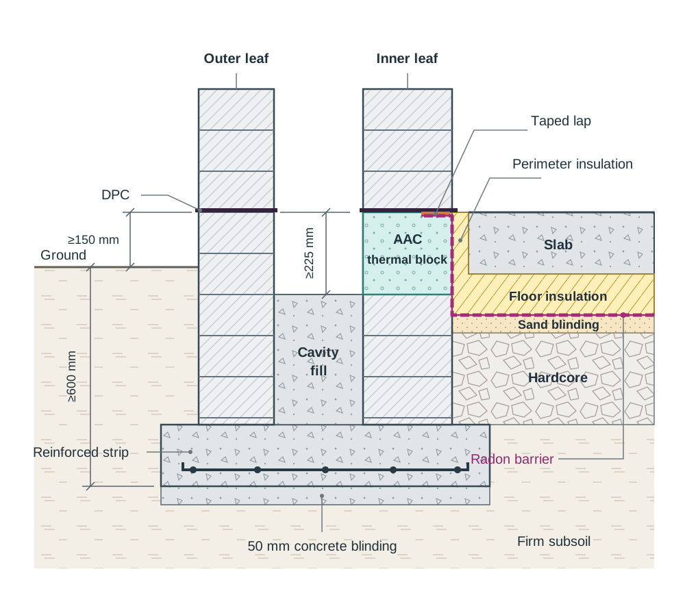
In compulsory Question 1 drawing questions, the foundation-to-wall detail must demonstrate compliance with current Part L thermal requirements and Part C moisture and radon standards:
- Foundation strip: Draw the reinforced concrete strip foundation resting on a blinding bed, positioned safely below ground level (minimum 600 mm to footing underside).
- Rising blockwork and cavity fill: Draw outer and inner concrete block leaves. Fill the cavity with lean-mix concrete up to a level at least below the damp-proof course (DPC) to brace the blockwork against external backfill ground pressures.
- Thermal bridge prevention: Install an autoclaved aerated concrete (AAC) thermal block as the first course of the inner leaf at floor level. Thermal blocks have low thermal conductivity and stop heat escaping diagonally downward through the inner leaf into the cold foundation.
- Perimeter insulation: Fit a to vertical strip of rigid insulation between the perimeter edge of the floor slab and the inner leaf. This must join continuously with the sub-floor slab insulation.
- Radon barrier and DPC: Lay a heavy-duty radon barrier over a sand blinding layer across the hardcore bed. Lap and seal the radon barrier to the wall DPC using double-sided butyl tape, and fit a cavity tray where necessary. The wall DPC must sit at least above the finished external ground level.
Key terms
- Dead Load
- The static, permanent self-weight of all fixed structural elements in a building, such as walls, floors, roofs, and structural timber or steel.
- Imposed (Live) Load
- The variable, movable loads applied to a building from occupants, furniture, stored equipment, and snow. Wind is treated as a separate lateral and uplift environmental load.
- Bulb of Pressure
- The stressed zone of subsoil beneath a loaded footing, mapped as curved isobar contours that indicate diminishing stress with depth.
- Differential Settlement
- Unequal downward movement between different sections of a building's foundations, causing distortion of the frame and diagonal stepped cracking in walls.
- Subsidence
- Downward ground movement beneath a foundation caused by external environmental factors independent of building weight, such as washed-out soil fines from leaking pipes.
- Frost Heave
- The upward lifting of shallow footings caused by groundwater freezing, expanding by 9%, and creating ice lenses in upper soil layers.
- Ground Heave
- The upward swelling of cohesive clay soil as it re-absorbs moisture over several seasons, commonly triggered when a mature tree is felled close to a foundation.
- Profile Board
- A temporary horizontal timber board supported by pegs outside the excavation area, used to mark wall lines and trench widths with saw kerfs or nails.
- Pad Foundation
- An isolated, reinforced concrete block designed to spread a concentrated point load from a column or pier safely into the ground.
- Ground Beam
- A reinforced concrete beam cast horizontally at or near ground level to span between piles or pad footings and support rising masonry walls.
- Spacer Chair
- A plastic or concrete support used to elevate steel reinforcement off the trench base, maintaining a specified concrete cover (50 mm on blinding, 75 mm on earth).
- Water/Cement Ratio
- The mass of water divided by the mass of cement in a concrete mix, which governs the compressive strength, durability, and porosity of the cured concrete.
Check yourself
What is the key structural rule governing the depth of an unreinforced concrete strip foundation?
The depth D must be at least equal to the projection P (D >= P) and never less than 150 mm, keeping the load spread within a safe 45-degree angle in pure compression.
Give two practical site methods for managing ground water in an open foundation trench.
Divert surface water using an uphill cut-off (French) drain, and pump standing water out of a collection sump dug at the lowest point of the excavation.
What are the structural consequences of adding too much water to a concrete mix?
Excess water increases the water/cement ratio, causing bleeding, higher porosity, lower compressive strength, and increased drying shrinkage cracking.
Why are foundation piles positioned either side of window openings rather than directly beneath them?
The lintel over the opening carries the wall load above it to the solid wall (jambs) at each side. The load therefore reaches the ground beam at those points, so the piles are placed under the solid wall either side of the opening.
What two thermal detailing features at rising wall level reduce cold bridging in a strip foundation?
A low-conductivity thermal block placed at the base of the inner leaf, and continuous vertical perimeter insulation fitted between the floor slab edge and the wall.