
Computer Aided Manufacture (CAM) uses computer software and programmable machinery to turn digital designs into physical components. In the Junior Cycle examination, you will need to explain the CAD/CAM workflow, select suitable subtractive or additive processes for given parts, and evaluate them using principles of accuracy, safety, and finish.
The CAD to CAM Workflow and Mechatronics
CAD and CAM connect design and production into one digital workflow:
- CAD (Computer-Aided Design): Software used to create 2D working drawings and 3D digital models on screen.
- CAM software: Uses the CAD drawing or model to prepare instructions for manufacture. A toolpath is the route a cutting tool follows.
- CNC (Computer Numerical Control): Programmed numerical instructions control a machine tool's movements.
CAM operates as a mechatronic system with three core stages:
- Input: The digital program, toolpaths, and sensor signals.
- Process: The computer controller interprets code and directs machine actions.
- Output: Motors move the cutting tool, bed, or printhead to shape the material.
CAM Processes: Subtractive and Additive
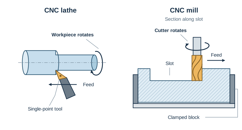
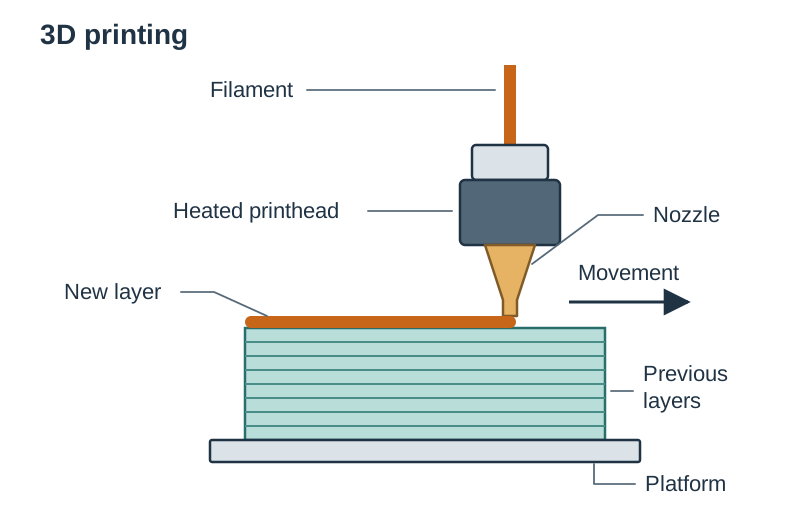
These CAM examples either remove material or build a part in layers. Subtractive processes cut waste material away from a solid block or sheet. Additive processes build the part up in thin layers.
| Machine | Process Type | Operation | Typical Uses |
|---|---|---|---|
| CNC Lathe | Subtractive | Workpiece spins while a single-point tool cuts cylindrical shapes | Turning metal pins, brass bushings, and threaded shafts |
| CNC Mill | Subtractive | Rotating multi-edge cutter removes material along X, Y, and Z axes | Machining slots, pockets, and flat bracket surfaces |
| Laser Cutter | Subtractive | High-powered light beam vaporises or melts a narrow cut path | Profiling 2D acrylic robot arms and plywood chassis plates |
| 3D Printer | Additive | Extrudes heated plastic filament layer upon layer | Rapid prototyping and curved, lightweight drone casings |
Advantages, Disadvantages, and Impact on Workers
Choosing CAM depends on production scale, material choice, and cost.
Advantages
- Correct programming and setup help CAM produce accurate parts.
- Excellent repeatability: Repeated parts have closely similar dimensions.
- Automatic repetition can reduce production time.
- The program can be saved and re-run whenever spare parts are needed.
Disadvantages
- Equipment and software require high initial capital investment.
- Operators need specialist technical training to program and set up machines.
- A single programming or setup error can ruin a whole batch of material.
Impact on Workers
Automated manufacturing replaces repetitive, dangerous manual tasks and shifts factory roles toward programming, machine setup, quality inspection, and maintenance.
Simulation, Safety, and Surface Finish
Simulation and Safety
A digital simulation tests toolpaths on screen before cutting real material. It identifies tool clashes, incorrect depths, and coordinate errors early, reducing tool breakage and material scrap.
- Secure material as instructed and keep required guards closed.
- Use suitable ventilation or extraction; never laser-cut PVC.
- Stop the machine and wait for moving parts to stop before measuring or clearing waste.
Surface Finish
Check finished dimensions and surface finish against the drawing. Remove sharp burrs where needed. Printed parts may need support removal or smoothing.
Key terms
- CAM
- Computer Aided Manufacture: using computer systems to direct and control manufacturing equipment.
- CAD
- Computer-Aided Design: software used to create detailed 2D working drawings and 3D computer models.
- CNC
- Computer Numerical Control: the automatic control of machine tools using coded numerical data.
- Subtractive Manufacturing
- A method that creates parts by cutting away unwanted material from a solid workpiece.
- Additive Manufacturing
- A method that creates parts by joining material layer upon layer, as in 3D printing.
- Simulation
- Testing a machine program virtually on screen to detect toolpath errors before cutting material.
- Repeatability
- How closely repeated results agree under the same conditions.
- Prototype
- The first full-size, complete item of a product used to test and refine a design.
Check yourself
What are the three main stages of a mechatronic CAM system?
Input (the coded program), Process (the computer controller), and Output (motors moving the tool or workpiece).
Which CAM process is best suited for producing a cylindrical brass bushing?
A CNC lathe.
Why is a machining simulation run before manufacturing begins?
It detects toolpath mistakes and tool collisions on screen, protecting tools and saving material.
State one disadvantage of using CAM for a single, one-off component.
Equipment and software are expensive, and programming the part takes significant setup time.
What finishing step is normally needed on a CNC-milled metal part?
Remove sharp burrs with a suitable file or deburring tool, where needed.