

Reflection is the bouncing back of a wave from a surface. Light reflects at the same angle at which it arrives, measured from the normal. Plane mirrors form upright, virtual images the same distance behind the mirror as the object is in front.
The Wave and Ray Models of Reflection
Reflection occurs across all types of waves, including sound, water, and electromagnetic radiation. When waves hit a barrier, they rebound back into the original medium.
Reflection as a wave effect
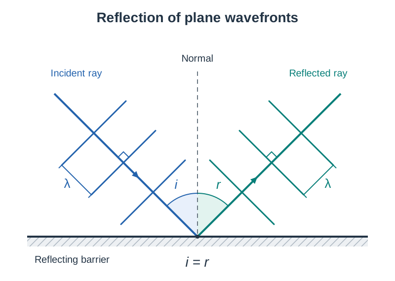
A wavefront is a line or surface joining points of a wave that are in step (in phase), such as all the points along one crest. Successive crest wavefronts are one wavelength apart. A ray is a line drawn at to the wavefronts showing the direction of energy propagation.
When straight (plane) wavefronts hit a flat barrier at an angle, each section of the wavefront reflects in sequence. The reflected wavefronts leave at the exact same angle to the barrier as the incident wavefronts arrived. On reflection, the frequency, wavelength, and wave speed do not change because the wave remains in the original medium. Only the direction of travel changes. If the surface absorbs some energy, the amplitude of the reflected wave decreases.
Diagram construction: Draw a straight line for the reflecting barrier. Draw three equally spaced parallel lines approaching at an angle to represent incoming wavefronts, with an incident ray arrow at to them. At the point of contact, draw a dashed normal perpendicular to the barrier. Draw three reflected wavefronts leaving the surface with identical spacing (same wavelength ) and a reflected ray arrow at to them, ensuring the angle between the incident ray and the normal () equals the angle between the reflected ray and the normal ().
Specular versus diffuse reflection
- Specular (regular) reflection: Occurs on smooth, polished surfaces such as mirrors or calm water. Parallel incident rays reflect parallel to each other, forming a clear visual image.
- Diffuse reflection: Occurs on rough or uneven surfaces such as paper or walls. Microscopic irregularities mean the surface normals point in random directions. Incoming parallel rays scatter in many directions, making the surface visible from any angle without forming an image.
The Two Laws of Reflection
Every individual ray obeys the laws of reflection:
- The incident ray, the reflected ray, and the normal at the point of incidence all lie in the same plane.
- The angle of incidence equals the angle of reflection: .
The normal is an imaginary line drawn perpendicular () to the reflecting boundary at the point of incidence. Always measure angles and from the ray to the normal, never to the mirror face.
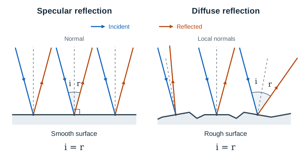
Image Formation in Plane Mirrors
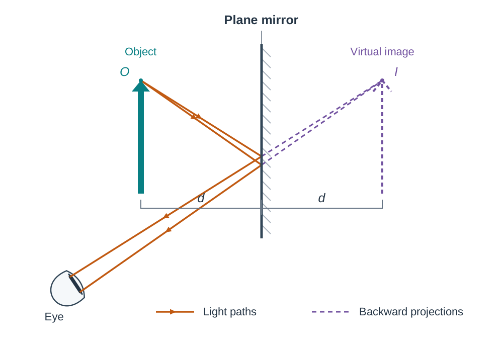
A plane mirror has a flat reflecting surface. When an object stands in front of it, diverging rays strike the glass, reflect obeying , and enter the observer's eye.
Your eye and brain assume light always travels in straight lines, so the reflected rays seem to come from a point behind the mirror. Because the rays actually diverge after reflection, they never meet in real space. Their backward projections meet behind the mirror at a point through which no light energy passes. This forms a virtual image, which cannot be projected onto a physical screen.
Properties of plane mirror images
- Virtual: Formed by the apparent intersection of light rays traced behind the mirror.
- Upright: It maintains the same vertical orientation as the object.
- Magnification of 1: The image is identical in size to the object ().
- Equal distance: The image is formed at the same perpendicular distance behind the mirror as the object is in front. Under the real-is-positive convention, virtual image distances are negative, so .
- Laterally inverted: Left and right orientations are reversed. Emergency vehicles use this property by printing 'AMBULANCE' in reverse on the front bonnet so drivers view it correctly oriented in their rear-view mirrors.
Constructing the plane mirror ray diagram
- Draw a straight line for the mirror surface and add diagonal hatching to the non-reflecting rear face.
- Place an object point at a chosen perpendicular distance in front of the mirror.
- Measure that exact same distance directly behind the mirror along a normal line and mark the virtual image point .
- Draw two separate diverging incident rays from to different strike points on the front surface of the mirror, adding directional arrows pointing towards the mirror.
- Line up your ruler with and the point where one incident ray hits the mirror. Draw the section behind the mirror (from to the glass) as a dashed line with no arrow. Continue that line in front of the mirror as a solid reflected ray, with an arrow pointing away from the mirror towards the eye. Repeat this step for the second ray.
Curved Mirror Geometry and Aberration
Spherical mirrors are sections of a sphere. Their optical behaviour depends on which face reflects light:
- Concave (converging) mirror: Curves inwards like the inside of a spoon. Rays travelling parallel to the principal axis reflect inwards to meet at a real focus in front of the mirror.
- Convex (diverging) mirror: Bulges outwards. Rays travelling parallel to the principal axis reflect outward as if spreading from a virtual focus behind the mirror.
Key geometric terms
- Pole (): The geometric centre of the curved mirror surface.
- Centre of curvature (): The centre of the sphere of which the mirror is a section. The distance from to is the radius of curvature (). Any straight line drawn from to the mirror surface is a radius, making it a true normal () to the surface at that point.
- Principal axis: The straight line passing through both and .
- Principal focus (): The point on the principal axis where rays incident parallel to the axis converge after reflection (concave mirror), or appear to diverge from (convex mirror).
- Focal length (): The distance along the principal axis from the pole to the focus . For spherical mirrors with small apertures, .
Spherical aberration and parabolic mirrors
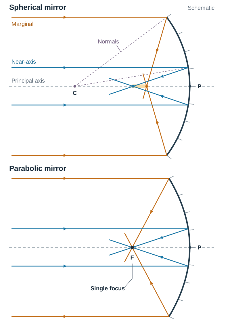
Wide spherical mirrors suffer from spherical aberration. Rays striking the outer rim of the mirror reflect and cross the principal axis closer to the pole than rays striking near the centre. This spreads the focal point along the axis and blurs the image.
A parabolic mirror solves this defect. Its cross-section follows a parabola, reflecting incoming rays parallel to its principal axis to one focal point.
Curved Mirror Ray Tracing and Image Regimes
To locate an image formed by a curved mirror geometrically, trace any two of four standard construction rays from the top of the object:
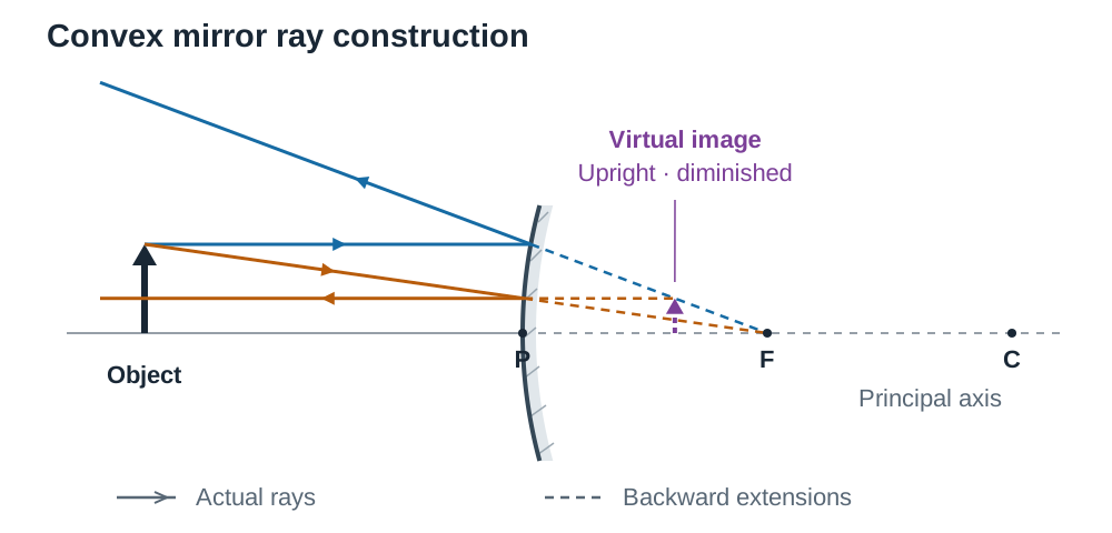
- Parallel ray: A ray parallel to the principal axis reflects through the focus (concave mirror) or reflects along a line aligning with the virtual focus behind the mirror (convex mirror).
- Focal ray: A ray passing through (concave mirror) or travelling towards behind the mirror (convex mirror) reflects parallel to the principal axis.
- Centre of curvature ray: A ray passing through (concave mirror) or directed towards (convex mirror) hits the mirror along the normal () and reflects straight back on itself.
- Pole ray: A ray striking reflects across the principal axis such that the angle of reflection equals the angle of incidence ().
Concave mirror image regimes
| Object Position | Image Position | Nature | Orientation | Size |
|---|---|---|---|---|
| Beyond | Between and | Real | Inverted | Diminished () |
| At | At | Real | Inverted | Same size () |
| Between and | Beyond | Real | Inverted | Magnified () |
| At | At infinity | Rays reflect parallel; no image forms | — | — |
| Inside () | Behind mirror | Virtual | Upright | Magnified () |
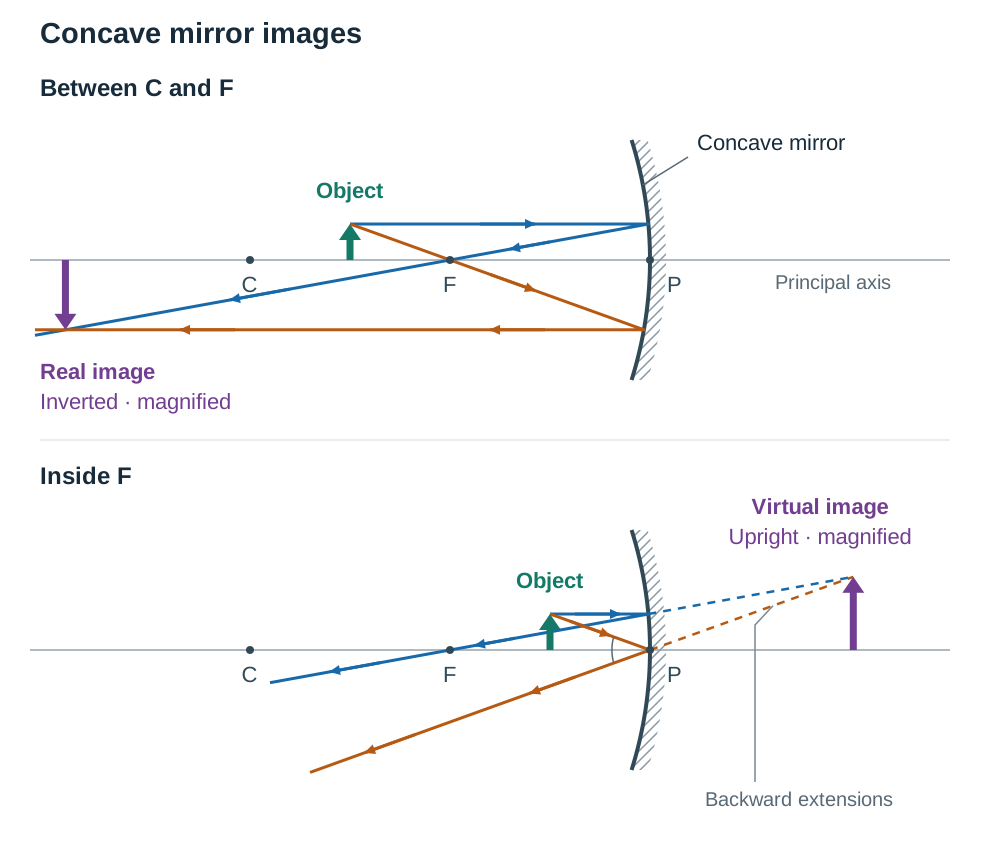
Step-by-step ray diagram: object between C and F
- Draw the principal axis as a horizontal line. Draw the concave mirror curving towards the left. Mark where the axis touches the mirror.
- Mark and along the axis in front of the mirror, ensuring is exactly halfway between and .
- Draw the object as an upright arrow standing on the axis between and .
- Ray 1: From the top of the arrow, draw a horizontal ray parallel to the axis to the mirror surface. Draw the reflected ray passing back through and extend it well beyond .
- Ray 2: From the top of the arrow, draw a ray passing down through to hit the mirror. Draw the reflected ray travelling back parallel to the axis.
- Where these two solid reflected rays intersect beyond , draw an arrow pointing downwards from the axis. This represents the image: real, inverted, and magnified.
Convex mirror image formation
A convex mirror has only one image regime: the image is always virtual, upright, diminished (), and located behind the mirror between and , no matter where the object stands.
The Mirror Formula and Sign Convention
For these curved-mirror calculations, we use the 'real is positive' sign convention. The mirror formula below uses the paraxial approximation: rays stay close to the principal axis and make small angles with it.
Sign rules
- Real distances are positive ().
- Virtual distances are negative ().
- Concave mirror: focal length is positive ().
- Convex mirror: focal length is negative ().
- Real image (in front of mirror): image distance is positive ().
- Virtual image (behind mirror): image distance is negative ().
- Real object in front of the mirror has a positive object distance ().
The optical relationship linking focal length , object distance , and image distance is:
Magnification () is the ratio of image height to object height, which equals the ratio of image distance to object distance:
Notice that for a plane mirror, which has zero curvature (, so ), the formula gives , leading directly to . A plane mirror is mathematically a curved mirror with an infinite radius of curvature.
Technological and Medical Applications of Reflection
Curved mirrors are used widely across engineering, astronomy, and clinical practice. For each application, practise naming the mirror, describing the image it forms, and explaining why it suits the job.
- Security and blind-spot mirrors (convex): Convex mirrors provide a wide field of view because their outward curvature compresses a broad scene into an upright, diminished virtual image. They help eliminate blind spots at concealed road junctions, shopping aisles, and on vehicle side mirrors.
- Shaving, make-up, and some dental mirrors (concave): When an object is placed inside the focus (), a concave mirror produces an upright, magnified, virtual image. This allows someone shaving or a dentist inspecting a tooth to examine fine detail easily.
- ENT head mirrors (concave): Ear, nose, and throat doctors use a concave head mirror with a central hole to concentrate light from an external lamp onto the patient's ear canal or throat, while looking through the hole along the beam of light.
- Solar concentrators (parabolic): Parabolic mirrors track the Sun and reflect incoming parallel sunlight onto a central pipe or receiver at the focus. The intense thermal energy boils a fluid to create steam, driving a turbine to produce electricity with low carbon emissions.
- Astronomical reflecting telescopes (concave parabolic): Large telescopes use curved primary mirrors rather than objective lenses. Mirrors have no chromatic aberration: glass lenses refract and disperse colours by slightly different amounts so they focus at different points, whereas reflection obeys identically for all colours. Mirrors can also be supported mechanically across their entire rear surface, which prevents heavy glass from sagging under its own weight.
Key terms
- Reflection
- The bouncing back of a wave (such as light) when it strikes a surface or boundary between two media.
- Wavefront
- A line or surface connecting points of a wave that are vibrating in step or in phase.
- Normal
- An imaginary line constructed perpendicular (at 90 degrees) to an optical surface at the point of incidence.
- Angle of Incidence
- The angle between the incident ray and the normal at the point of incidence.
- Angle of Reflection
- The angle between the reflected ray and the normal at the point of incidence.
- Real Image
- An optical image formed by the actual intersection of light rays, which can be formed on a screen.
- Virtual Image
- An optical image formed by the apparent intersection of rays traced backwards, which cannot be formed on a screen.
- Lateral Inversion
- The reversal of left and right in an image formed by reflection in a mirror.
- Principal Focus
- The point on the principal axis where rays incident parallel to the axis converge after reflection (concave), or appear to diverge from (convex).
- Focal Length
- The distance along the principal axis from the pole of a mirror to its principal focus.
- Magnification
- The ratio of image height to object height, equal to the ratio of image distance to object distance (m = |v| / u).
- Spherical Aberration
- The blurring of an image formed by a spherical mirror of wide aperture, caused by marginal rays focusing closer to the pole than central paraxial rays.
- Parabolic Mirror
- A curved mirror with a parabolic cross-section that reflects incoming rays parallel to its principal axis to a single focal point, eliminating spherical aberration.
- Centre of Curvature
- The centre of the sphere of which the curved mirror forms a surface section.
Check yourself
A ray of light strikes a flat mirror at an angle of 35 degrees to the mirror face. What is the angle of reflection?
55 degrees. The angle of incidence is measured from the normal: i = 90 - 35 = 55 degrees. Under the second law of reflection, r = i = 55 degrees.
State two fundamental differences between a real image and a virtual image.
1. A real image is formed by the actual intersection of light rays, whereas a virtual image is formed by the apparent intersection of rays traced backwards. 2. A real image can be captured on a physical screen, while a virtual image cannot.
What wave properties remain unchanged when a light wave undergoes reflection from a mirror?
Frequency, wavelength, and wave speed remain unchanged because the wave stays in the same medium. Only the direction of the wave changes.
A convex mirror has a focal length of 30 cm. An object stands 60 cm in front of it. Find the image distance v and describe the image.
Using 1/f = 1/u + 1/v with f = -30 cm and u = +60 cm: 1/v = -1/30 - 1/60 = -2/60 - 1/60 = -3/60 = -1/20, so v = -20 cm. The image is virtual, 20 cm behind the mirror, upright, and diminished (m = 20/60 = 0.33).
Why do large astronomical telescopes use concave parabolic mirrors rather than large glass lenses?
Mirrors eliminate chromatic aberration because reflection obeys i = r for all colours equally, avoid spherical aberration due to their parabolic shape, and can be supported from behind across their entire structure to prevent sagging.