

If the magnetic field passing through a coil of wire changes, a voltage appears across the coil. This voltage is called an induced electromotive force (emf). If the coil forms part of a complete circuit, the emf drives an induced current. This fundamental phenomenon, discovered by Michael Faraday, is called electromagnetic induction. The size of the induced emf depends on how fast the magnetic flux changes over time (Faraday's law), while the direction of the induced current always acts to oppose the change causing it (Lenz's law). This principle underpins alternating-current generators, electrical transformers, and high-voltage transmission across the national electricity grid.
Magnetic Flux and Faraday's Law
Magnetic flux (symbol ) is a measure of how much magnetic field passes through an area. For a uniform field at right angles to a flat surface of area , it is defined as:
where is the magnetic flux density in teslas (T) and is the area in square metres (). The SI unit of magnetic flux is the weber (Wb).
Unit check: . Since induced emf is rate of change of flux, , which means . Checking units this way helps confirm whether an equation or answer makes sense.
Faraday's Law of Electromagnetic Induction states that the magnitude of the induced electromotive force is directly proportional to the rate of change of magnetic flux.
For a single loop of wire, . For a coil of turns, the flux links every turn, giving:
The minus sign comes from Lenz's law and indicates the direction of the induced effect. When calculating the numerical magnitude of the average emf in Leaving Certificate questions, we use:
Notice that an induced emf is set up across the ends of a conductor whenever the flux changes, regardless of whether a current can flow. An induced current flows only when there is a complete electrical circuit.
Lenz's Law and Conservation of Energy
Lenz's Law states that the direction of an induced current is always such that it opposes the change producing it.
The negative sign in is the mathematical representation of Lenz's law. The induced current creates its own magnetic field that fights the change in the external field.
Push the north pole of a bar magnet towards a coil connected in a complete circuit with a sensitive galvanometer:
- As the north pole moves closer, the magnetic flux through the coil increases.
- By Lenz's law, the induced current makes the near end of the coil a north pole.
- Two like poles repel each other, pushing back against the advancing magnet.
- To keep the magnet moving forwards, you must do external mechanical work against this repulsive force.
- That mechanical work is converted directly into electrical energy in the coil.
- When you pull the north pole away, the flux inside the coil decreases. The induced current reverses direction immediately, turning the near end into a south pole that attracts the departing magnet. You must again do mechanical work to pull it free.
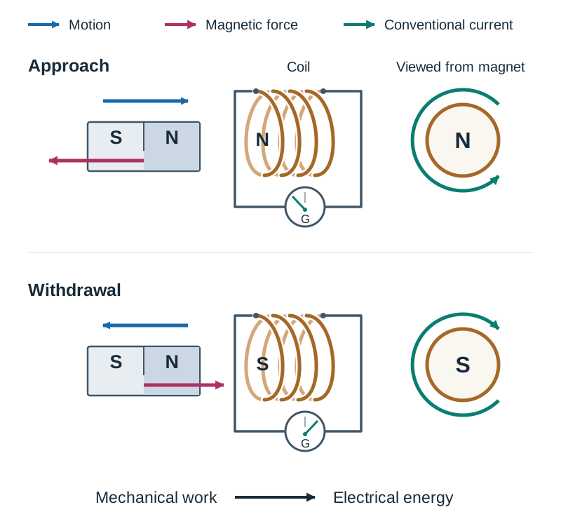
If Lenz's law did not hold—if an approaching north pole induced an attracting south pole instead—the magnet would accelerate towards the coil on its own. It would gain kinetic energy while simultaneously producing electrical energy, generating energy out of nowhere. Lenz's law is therefore an unavoidable consequence of the Principle of Conservation of Energy.
Demonstrating and Investigating Electromagnetic Induction
Demonstrating Faraday's and Lenz's Laws
- Magnet and coil: Connect a multi-turn coil to a centre-zero galvanometer. Push a bar magnet into the coil to see a momentary deflection. Hold the magnet stationary inside: the pointer returns to zero because the flux is constant. Pull the magnet out: the pointer deflects in the opposite direction. Moving the magnet faster produces a larger deflection, showing that a faster rate of change of flux induces a larger emf. Note that a qualitative meter deflection alone cannot verify direct proportionality; verifying proportionality requires recorded measurements and a plotted graph.
- Suspended aluminium ring: Hang a solid, lightweight aluminium ring from a stand. Thrust a magnet towards the ring: the ring swings away due to repulsion. Pull the magnet away: the ring is drawn after it due to attraction. If you test an identical aluminium ring with a slit cut across it, the ring does not move. The slit breaks the conducting loop, preventing circulating current and magnetic poles from forming, even though an emf is still induced across the slit.
- Magnet in a copper pipe: Drop a non-magnetic metal cylinder through a vertical copper pipe: it falls freely under gravity. Drop a strong neodymium magnet of identical size and mass through the pipe: it falls much more slowly. As the magnet drops, its moving field induces circulating currents, known as eddy currents, in the walls of the copper pipe. By Lenz's law, these currents create an opposing magnetic field that exerts an upward braking force on the magnet.
Quantitative Primary Investigation: Measuring Peak EMF
To investigate how induced emf depends on the speed of flux change with primary data:
- Aim: Investigate the relationship between peak induced emf and magnet velocity.
- Apparatus: A coil connected to a voltage sensor and data logger (or oscilloscope), a bar magnet, a vertical transparent guide tube, and a metre stick.
- Method: Drop the magnet, north pole first, down the tube through the coil from a measured height . The data logger records the peak voltage. Repeat three times for each height to find an average, and repeat for at least six different drop heights.
- Variables: Independent variable is drop height , giving entry speed ; dependent variable is peak emf; controlled variables are using the same magnet, the same coil, and dropping with the same pole downwards.
- Analysis: Plot peak emf against (which is proportional to speed). A straight line through the origin verifies that induced emf is directly proportional to the speed of flux change.
- Sources of error: Random error occurs if the magnet rubs or tilts inside the tube; systematic error occurs if the drop height is misread from the wrong edge of the magnet or if the data-logger sampling rate is too low to record the true peak.
AC and DC Generators
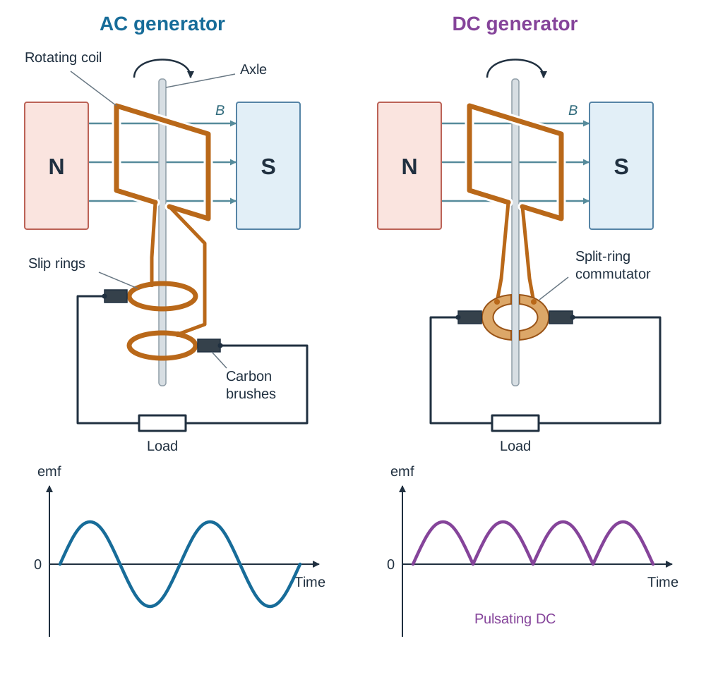
An electrical generator converts mechanical energy into electrical energy using electromagnetic induction. A rectangular coil (armature) mounted on an axle is rotated inside a magnetic field.
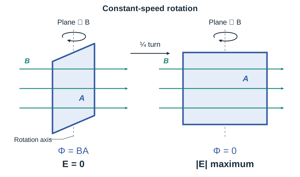
As the coil turns, the flux through it changes continuously. The induced emf is zero when the plane of the coil is perpendicular to the magnetic field (where flux is momentarily maximum but not changing). The emf reaches its maximum peak when the plane of the coil is parallel to the field lines (where the coil cuts field lines fastest, giving the maximum rate of flux change).
Drawing and Modelling an AC Generator
To draw an AC generator, sketch:
- A north magnetic pole on the left and a south magnetic pole on the right, providing a horizontal magnetic field.
- A rectangular coil between the poles, mounted on an axle.
- Two circular slip rings fixed to the axle, each connected to one end of the coil.
- Two fixed carbon brushes that press against the slip rings, connecting the rotating coil to the external circuit.
- Output graph: A smooth sine wave alternating equally above and below the time axis. The current constantly reverses direction in the external circuit.
Drawing and Modelling a DC Generator
To draw a DC generator, use the exact same magnet and coil arrangement, but replace the two separate slip rings with a single split-ring commutator—a metal ring split into two semicircular halves separated by an insulating gap.
- The brushes swap contact from one half of the commutator to the other every half-turn. This changeover happens when the plane of the coil is perpendicular to the field, the moment the induced emf is zero.
- Output graph: A sequence of positive humps that touch zero every half-cycle but never cross below the axis. The current always flows in one direction through the external circuit, producing pulsating DC.
Root Mean Square (RMS) Alternating Current
Alternating current (AC) repeatedly reverses its direction of flow. In Ireland, the national mains electricity supply operates at a frequency of , completing 50 full cycles and changing direction 100 times every second.
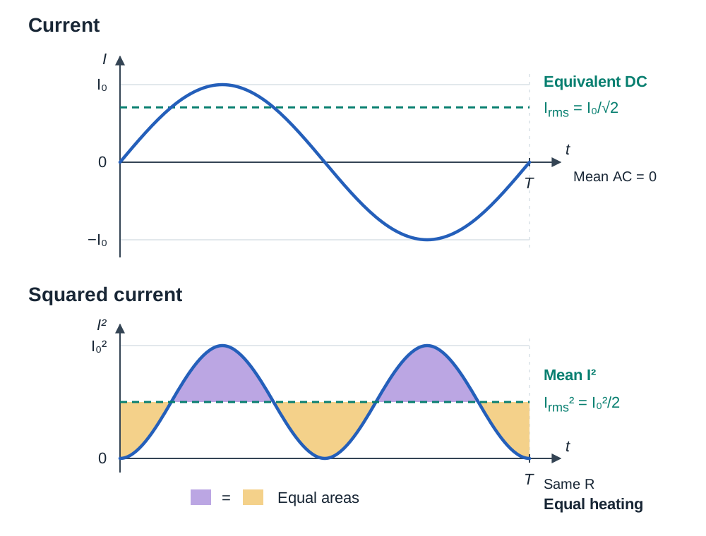
Because current reverses symmetrically, the simple average value of AC over a full cycle is zero. However, heating in a resistor depends on , which is always positive regardless of the direction the current flows. To compare the heating power of alternating current with steady direct current, we use the root mean square value.
The Root Mean Square (rms) value of an alternating current (or voltage) is the value of steady direct current (or voltage) that produces the same heating effect in an identical resistor.
For a sinusoidal waveform, the formulas linking rms and peak values ( and ) are:
When Irish mains electricity is stated as , this is an rms value. The actual peak voltage reaches:
All electrical power formulas for AC require rms values: .
Transformers, Mutual Inductance, and Efficiency
Mutual inductance is the process where a changing electric current in one circuit induces an electromotive force in an adjacent circuit through changing magnetic flux.
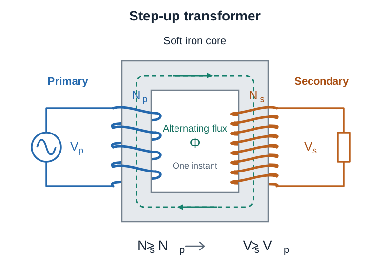
A transformer uses mutual inductance to change alternating voltage levels. It consists of two separate coils of insulated wire wound onto a soft iron core:
- An alternating voltage applied to the primary coil ( turns) drives an alternating current.
- This current creates a continuously alternating magnetic flux in the core.
- The soft iron core guides this changing flux through the secondary coil ( turns).
- By Faraday's law, an alternating emf is induced across the secondary terminals.
Because the same magnetic flux links both coils, the voltage ratio equals the turns ratio (transformer equation):
- Step-up transformer: More turns on secondary (), so secondary voltage is higher ().
- Step-down transformer: Fewer turns on secondary (), so secondary voltage is lower ().
- Why transformers require AC: A steady DC produces a constant magnetic field once turned on. With no change in flux (), zero emf is induced in the secondary coil.
Efficiency of a Real Transformer
For an ideal transformer with no energy losses, input power equals output power: . Real transformers lose some power as heat, so efficiency is defined as:
Energy losses in transformers arise from four causes:
- Joule heating ( losses): Current flowing through winding resistance produces heat. Minimised by using thick, low-resistance copper wire.
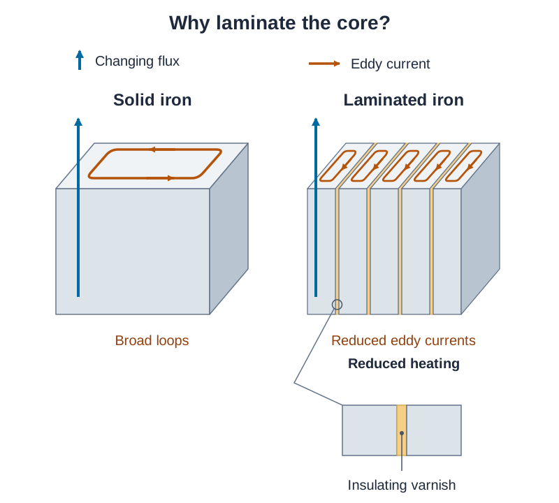
- Eddy currents: Changing flux induces circulating currents in the conductive iron core. Minimised by using a laminated core made of thin sheets of soft iron separated by insulating varnish.
- Hysteresis: Energy is used repeatedly magnetising and demagnetising the iron core each cycle. Minimised by using magnetically soft iron.
- Flux leakage: Not all magnetic field lines from the primary pass through the secondary coil. Minimised by winding coils closely together on a closed core loop.
National Grid Transmission and Applications
High-Voltage Transmission on the National Grid
Electrical energy must travel long distances from generating stations to consumers through cables of resistance . The power lost as heat along these lines is:
Since power transmitted is , the required line current is . Substituting this gives:
Stepping up transmission voltage by a factor of 10 decreases power lost as heat by a factor of . Step-up transformers at power stations raise voltage to very high levels for long-distance lines. Near homes and towns, local substations use step-down transformers to reduce voltage to safe levels, ending at rms.
- Why the grid uses AC: Only alternating current allows transformers to step voltages up and down easily.
- Trade-offs of high voltage: Very high voltages require tall pylons, large ceramic insulators, and wide safety corridors. These increase construction costs and create visual impact or planning objections.
- Grid generation issues: Renewable generation such as wind and solar fluctuates with weather conditions, so grid operators must balance supply and demand in real time. Remote generating sites (like offshore wind farms) also require long transmission lines, increasing infrastructure needs.
Everyday Applications of Induced EMF
- Induction hobs: High-frequency AC in coils under ceramic glass produces changing magnetic fields that induce eddy currents in the iron or steel base of a pot, heating it directly.
- Wireless charging: An alternating current in the charging pad induces an alternating emf in a small coil inside the mobile phone via mutual induction.
- Electric guitar pickups: A vibrating steel guitar string alters the magnetic field through a coil wrapped around a permanent magnet, inducing an electrical audio signal.
- Regenerative braking: when an electric car slows down, the turning wheels drive the motor so that it acts as a generator. The changing flux in its coils induces an emf, converting the car's kinetic energy into electrical energy that recharges the battery, and this slows the car.
Key terms
- Electromagnetic Induction
- The production of an electromotive force across an electrical conductor when it experiences a changing magnetic flux.
- Magnetic Flux (Φ)
- The product of magnetic flux density and the perpendicular area through which it passes: Φ = BA. Its SI unit is the weber (Wb).
- Weber (Wb)
- The SI unit of magnetic flux; one weber is the flux passing perpendicularly through an area of one square metre when the flux density is one tesla (1 Wb = 1 T·m² = 1 V·s).
- Faraday's Law of Electromagnetic Induction
- The magnitude of the induced electromotive force is directly proportional to the rate of change of magnetic flux.
- Lenz's Law
- The direction of an induced current is always such that it opposes the change producing it.
- Root Mean Square (rms) Value
- The value of steady direct current (or voltage) that produces the same heating effect in an identical resistor as the alternating current (or voltage).
- Mutual Inductance
- The induction of an electromotive force in one circuit caused by a changing electric current in a neighbouring circuit.
- Transformer
- A device that alters the magnitude of an alternating voltage through mutual inductance between two coils wound on a common soft iron core.
- Eddy Currents
- Circulating electric currents induced within the body of a conductor by a changing magnetic flux, causing energy loss as heat.
- Laminated Core
- A transformer core constructed from thin sheets of soft iron separated by insulating varnish to restrict eddy currents and reduce heat dissipation.
Check yourself
What is the magnetic flux through a rectangular coil of dimensions 15 cm by 20 cm placed perpendicularly in a uniform magnetic field of 0.60 T?
Area A = 0.15 m × 0.20 m = 0.030 m². Because the field is perpendicular, Φ = BA = 0.60 T × 0.030 m² = 0.018 Wb.
The north pole of a bar magnet is pulled rapidly away from a coil. What magnetic pole is created at the near end of the coil, and why?
A south pole is created. By Lenz's law, the induced current opposes the decrease in magnetic flux by attracting the departing north pole.
Irish mains voltage is rated at 230 V rms. What peak voltage must domestic cable insulation withstand?
V₀ = V_rms × √2 = 230 V × 1.414 ≈ 325 V.
Why are transformer cores made of laminated sheets of soft iron rather than a single solid block?
Laminating the core with thin iron sheets separated by insulating varnish interrupts circulating electrical paths, reducing energy lost as heat from eddy currents.
A transformer with an efficiency of 90% takes 400 W of electrical power from the mains. What power does it supply to its load?
P_out = efficiency × P_in = 0.90 × 400 W = 360 W.
Why does stepping up voltage across national grid lines dramatically reduce energy wasted as heat?
Since transmitted power is P = VI, a higher voltage reduces line current I. Because line heat loss follows P_loss = I²R, power loss is inversely proportional to the square of voltage (P_loss ∝ 1/V²).