

An electric circuit is a complete loop that lets charge flow, carrying energy from a source (such as a battery or the mains) to devices that use it. In this topic you learn what current, voltage and resistance are, how to calculate them, how semiconductors like diodes and transistors work, and how the wiring in your home keeps you safe.
Current, Potential Difference, and Joule's Law
Current is how much charge passes a point each second, a bit like litres of water flowing through a pipe every second. Formally, electric current () is the rate of flow of electric charge:
Current is measured in amperes (A), where . By convention, conventional current is directed from positive to negative potential. In metallic conductors, the actual mobile charge carriers are free electrons drifting in the opposite direction, from negative to positive.
Potential difference is the energy given to or lost by each coulomb of charge. Potential difference (), or voltage, is the work done per unit charge in moving an electric charge between two points:
The unit is the volt (V), where . Electromotive force (emf) is the total work done per unit charge by a power source (such as a cell or generator) in driving charge around a complete circuit.
Combining these definitions gives the rate of electrical energy transfer, which is electric power ():
When mobile electrons drift through a conductor, they collide with vibrating lattice ions, transferring kinetic energy to the lattice as internal heat. In accordance with Joule's law, the rate of heat production is directly proportional to the square of the current ( for a constant resistance ). Substituting Ohm's law () gives the formulas for the electrical energy converted to heat () and the power ():
Because heating depends on , doubling the current through an element quadruples the rate of heat dissipation. For example, if a current flows through a heating coil for , the energy converted to heat is:
Resistance, Resistivity, and Derivations
Resistance is a measure of how strongly an object opposes the flow of electric current. Ohm's law states that the current flowing through a conductor is directly proportional to the potential difference across it, provided temperature and other physical conditions remain constant ().
The resistance of a uniform conductor depends on its physical dimensions and the material it is made of. This property is quantified by its resistivity (, measured in ):
where is conductor length in metres and is cross-sectional area in square metres. For a cylindrical wire of diameter , the cross-sectional area is .
Derivation: Resistors in Series
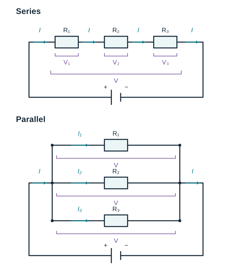
Consider three resistors , , and connected end-to-end in series across a total potential difference .
- By conservation of charge, the same current passes through each resistor in turn:
- By conservation of energy, the total work done per unit charge equals the sum of the potential differences across each individual resistor:
- Applying Ohm's law ():
- Dividing across by current gives the formula for the equivalent series resistance:
Derivation: Resistors in Parallel
Consider three resistors , , and connected across the same two junction points with total applied potential difference .
- The potential difference across each parallel branch is identical:
- By conservation of charge, the total current entering the junction equals the sum of the currents leaving the junction along the branches:
- Applying Ohm's law ():
- Dividing across by potential difference gives the formula for the equivalent parallel resistance:
Circuit Components, Meters, and Combination Experiments
Circuit Components and Meters
To read and draw circuit diagrams accurately, you need to know how each component acts and how meters must be connected:
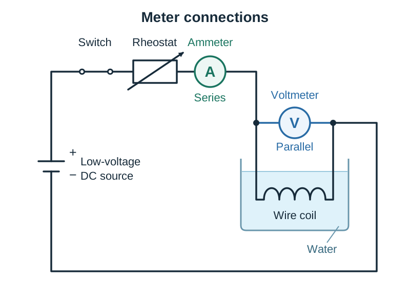
- Ammeter: Measures current in amperes. Connected in series with the component so that all the current passes through it. It has very low internal resistance so it does not restrict current.
- Voltmeter: Measures potential difference in volts. Connected in parallel across the component. It has very high internal resistance, so it draws almost no current away from the main branch.
- Ohmmeter: Measures resistance directly in ohms. The component must be disconnected from any power supply before measuring.
- Variable resistor (rheostat): Used to vary resistance and adjust the current flowing in a circuit.
Drawing Circuit Symbols
- Resistor: A simple rectangle.
- Variable resistor: A rectangle with a diagonal arrow through it.
- Diode: A triangle pointing at a vertical bar. Conventional current flows in the direction the triangle points.
- Light Emitting Diode (LED): The standard diode symbol enclosed or accompanied by two small arrows pointing outwards (representing emitted light).
- Light Dependent Resistor (LDR): A resistor rectangle inside a circle, with two arrows pointing inwards (representing incident light).
- Thermistor: A resistor rectangle with a diagonal line through it that ends in a short horizontal flat foot.
- Meters: A circle with A (ammeter), V (voltmeter), or (ohmmeter) written inside.
Investigating Resistors in Series and Parallel
- Purpose: To verify by experiment that in series and in parallel using primary data.
- Apparatus: Two or three resistors of known nominal value, digital ohmmeter (or DC power supply, ammeter, and voltmeter), and connecting leads.
- Method:
- Measure each individual resistor on its own using the ohmmeter and record its resistance.
- Connect two resistors in series. Measure and record the combined resistance.
- Connect the same two resistors in parallel. Measure and record the combined resistance.
- Repeat with a third resistor added to each arrangement.
- Results & Comparison: Compare each measured total with the value calculated from the theoretical formulas. In series, the total resistance equals the sum of the components. In parallel, the equivalent resistance is always less than the smallest single resistor in the network.
- Sources of error: Contact resistance at clip connections, connecting lead resistance, and heating of resistors if powered continuously when using the voltmeter-ammeter method.
Practical Investigations in Conduction and Characteristic Graphs
The specification requires you to gather and evaluate primary and secondary data for several core conduction relationships.
1. Verifying Ohm's Law for a Metallic Conductor
- Purpose: To verify that current is directly proportional to potential difference for a metal wire at constant temperature.
- Apparatus & Circuit: Low-voltage DC power supply, rheostat (or variable supply), switch, ammeter, and wire coil immersed in a beaker of water (to keep temperature steady), connected in series. A voltmeter is connected in parallel across the wire coil.
- Method: Close the switch and record corresponding values of current () and potential difference (). Adjust the rheostat to obtain at least six pairs of readings. Switch off the current between readings to prevent Joule heating.
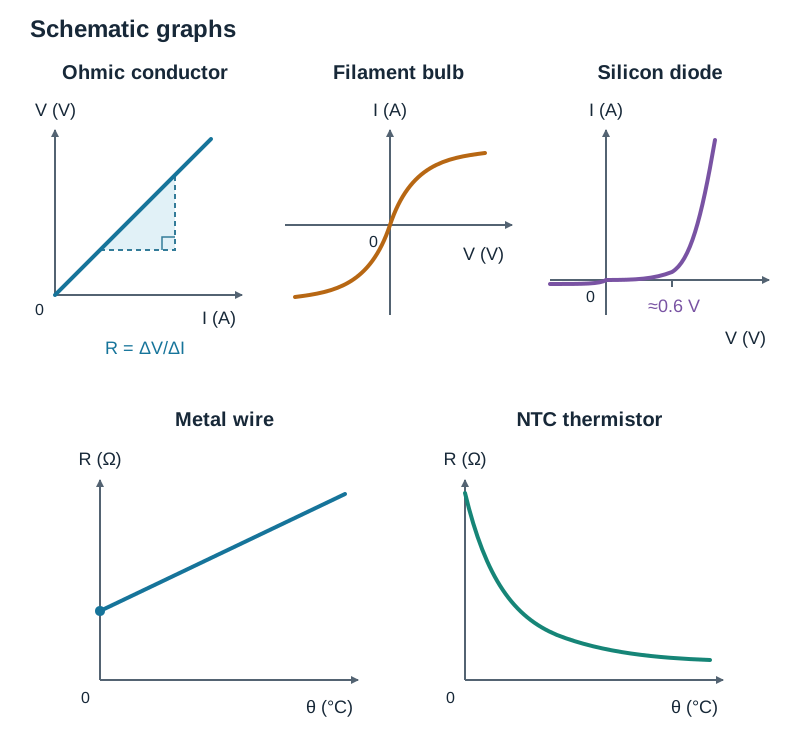
- Results & Graph: Plot potential difference on the y-axis against current on the x-axis. A straight line passing through the origin verifies Ohm's law (). The slope gives the resistance (). If is plotted on the y-axis against , the slope is .
- Sources of error: Temperature rise if current is left on; zero errors on meters.
2. Investigating Non-Ohmic Conductors: Filament Bulb and Diode
- Filament Bulb: Set up a circuit with a variable DC supply, an ammeter in series, and a voltmeter in parallel across the bulb. As voltage increases, current increases, but not proportionally. Electrical heating makes the tungsten filament hotter, increasing lattice vibrations and collision rates with electrons. This causes resistance () to increase. An graph is a curve through the origin that flattens out at higher voltages.
- Semiconductor Diode: Connect a variable DC supply, milliammeter, protective resistor, and silicon diode in forward bias (positive supply to p-side, negative to n-side). Place a high-resistance voltmeter across the diode. Almost no current flows until the applied voltage reaches about , after which current rises steeply. In reverse bias, reverse the supply connections and replace the milliammeter with a microammeter; current remains virtually zero (a tiny leakage current).
3. Investigating the Effect of Temperature on Resistance
- Metallic Conductor: Place a coil of copper wire inside a beaker of glycerol or water on a hotplate, beside a thermometer. Connect the coil terminals to an ohmmeter. Heat the liquid gently, stir thoroughly, and allow the temperature to become steady before taking each pair of readings ( and temperature ). The resistance of a metal increases steadily as temperature rises. A graph of against is approximately a straight line, but it does not pass through the origin because resistance is not zero at . Thus, increases linearly with , but is not directly proportional to Celsius temperature.
- Thermistor (NTC): Replace the coil with a negative temperature coefficient thermistor. As temperature rises, thermal energy frees extra charge carriers across the semiconductor material. Resistance decreases sharply. A graph of against is a steep downward curve.
Key Graphs to Recognise and Sketch
- Ohmic conductor ( vs ): Straight line passing through the origin.
- Filament bulb ( vs ): Smooth S-shaped curve passing through the origin, bending towards the voltage axis as resistance rises.
- Diode ( vs ): almost zero current in reverse bias; almost zero in forward bias until about 0.6 V, then a sharp, nearly vertical rise.
- Metal wire ( vs ): Straight line with a positive y-intercept (does not pass through the origin).
- Thermistor ( vs ): Curve falling steeply from a high initial resistance towards the temperature axis.
Semiconductor Physics, Diodes, and Everyday Applications
A semiconductor has an electrical resistivity intermediate between that of a conductor and an insulator (e.g. silicon). In pure silicon, conduction is limited because valence electrons are locked into covalent bonds.
Doping and Charge Carriers
Doping is adding tiny, controlled amounts of impurity atoms to a pure semiconductor to increase its conductivity:
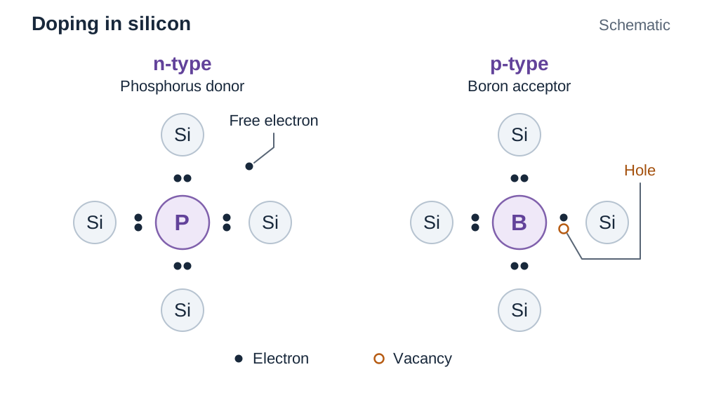
- n-type semiconductor: Pure silicon is doped with a Group V donor element (e.g. phosphorus). Four valence electrons bond with adjacent silicon atoms, leaving the fifth electron free. Free electrons are the majority charge carriers; positive holes are minority carriers.
- p-type semiconductor: Pure silicon is doped with a Group III acceptor element (e.g. boron). The atom has only three valence electrons, creating a vacancy or hole in the lattice. Holes behave as positive majority charge carriers; free electrons are minority carriers.
The p-n Junction
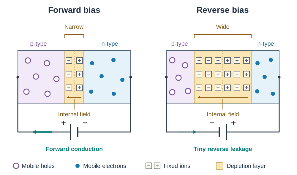
When p-type and n-type regions meet inside a single crystal, electrons near the junction cross into the p-side and fill nearby holes. This leaves fixed positive donor ions on the n-side and fixed negative acceptor ions on the p-side. This central non-conducting zone is the depletion layer; it contains fixed charged ions but almost no free charge carriers. These ions create an internal electric field and a barrier potential (around in silicon).
- Forward Bias: The positive terminal of an external supply connects to the p-side and the negative terminal to the n-side. This applied potential opposes the internal barrier field. Once the applied voltage is greater than about (for silicon), the depletion layer becomes very thin and current rises sharply.
- Reverse Bias: The positive terminal connects to the n-side and the negative terminal to the p-side. The external potential reinforces the internal field and widens the depletion layer. Only a very small leakage current flows, so the diode effectively blocks current in reverse bias.
Applications and Secondary Research
- Diode: Converts alternating current (AC) into direct current (DC) in power adapters, because current flows in one direction only.
- Light Dependent Resistor (LDR): When light falls on an LDR, it gives energy to electrons and frees more charge carriers. The brighter the light, the lower the resistance. Used in automatic street lighting.
- Thermistor: Resistance falls sharply as temperature rises. Used in digital thermometers, thermostats, and fire alarms.
- Light Emitting Diode (LED): Emits light when forward-biased as electrons recombine with holes. Used in energy-efficient home lighting and displays, wasting far less energy as heat than incandescent bulbs.
- Transistor: A three-terminal device (base, collector, emitter) where a small base current turns on a larger collector-emitter current. Billions of microscopic transistors act as digital switches inside computer processors.
- Solar (photovoltaic) cell: A large-area p-n junction that generates current when light strikes it, converting solar energy into electricity.
When researching applications using secondary sources, check reliability by asking: Who wrote or published it? Is the source recent? Could commercial interest introduce bias? Do other reputable sources agree?
Domestic Electrical Safety, Power Supply, and Transmission
Mains electricity in Ireland is supplied as alternating current (AC) at and a frequency of . Sockets and appliances are wired in parallel across the supply so that each receives the full and can be operated independently.
Three-Pin Plug and Cable Wiring
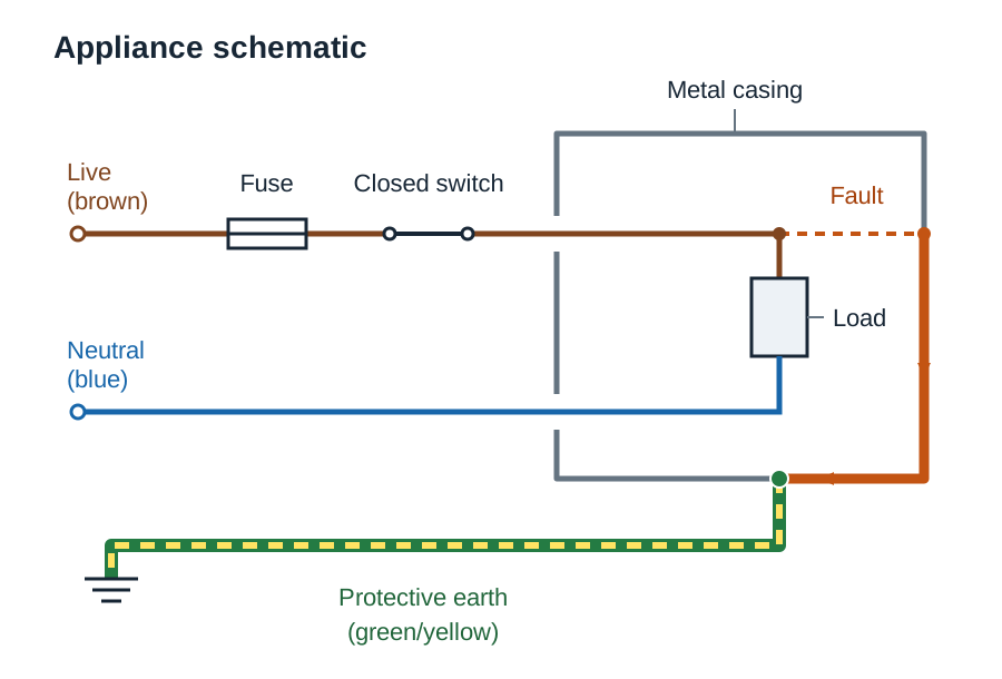
- Live wire (Brown): Carries the alternating high potential () relative to earth.
- Neutral wire (Blue): Completes the circuit back to the substation, maintained near earth potential ().
- Earth wire (Green/Yellow striped): A safety connection between the metal chassis of the appliance and the ground.
Switches, fuses, and circuit breakers must always be placed in the live wire. If placed in the neutral wire, opening the switch stops current from flowing, but the appliance remains live at . Anyone touching an internal part would still receive a lethal electric shock to ground.
Safety Devices in the Home
- Earthing: If a fault makes the live wire touch the metal casing, current flows through the low-resistance earth wire to the ground instead of through a person who touches the casing. This large current instantly blows the fuse or trips the MCB.
- Fuses: A short piece of thin wire that melts when current exceeds its stated rating (, , or ), isolating the circuit.
- Miniature Circuit Breakers (MCBs): Protect wiring against overcurrent caused by overloads or short circuits. They use a bimetallic strip for thermal protection and an electromagnet for instantaneous trip on high currents. MCBs operate faster than wire fuses and can be reset.
- Residual Current Devices (RCDs): Designed to protect people from electrocution. An RCD detects an imbalance between the live and neutral currents (). If as little as leaks to earth (for example, through a human body), the RCD trips within .
Cable Thickness and Power Heating
Appliances that draw large currents (like an electric shower or cooker) require thicker copper cables. Because the rate of heating in a cable is given by , a large current causes substantial heat dissipation. A thicker cable has a larger cross-sectional area , which lowers its resistance () and prevents overheating.
The Kilowatt-Hour and Domestic Electricity Billing
The commercial unit of electrical energy is the kilowatt-hour (kWh), defined as the energy converted by a appliance running for ().
Cost calculation: A heater used for consumes . At a unit rate of per kWh, it costs .
High-Voltage Power Transmission
Power stations transmit electricity over long distances using high voltages. Heating loss in cables is . From , transmitting power at a higher voltage requires a smaller current. Because loss depends on current squared (), stepping up the voltage using a transformer drastically reduces energy lost as heat across the national grid.
Key terms
- Electric Current
- The rate of flow of electric charge, defined by I = q / t and measured in amperes (A).
- Potential Difference
- The work done per unit charge in moving an electric charge between two points: V = W / q, measured in volts (V).
- Electromotive Force (emf)
- The total work done per unit charge by a power source in driving electric charge around a complete circuit.
- Ohm's Law
- The principle that current flowing through a conductor is directly proportional to the potential difference across it, provided temperature and other physical conditions remain constant.
- Resistivity
- The resistance of a conductor of unit length and unit cross-sectional area: ρ = (R A) / l, measured in ohm-metres (Ω m).
- Joule's Law
- The principle that the rate at which heat is produced in a conductor is directly proportional to the square of the electric current flowing through it for a constant resistance (P ∝ I²).
- Semiconductor
- A material whose resistivity lies between that of a conductor and an insulator, and whose resistance decreases as temperature increases.
- Depletion Layer
- The narrow region around a p-n junction that contains fixed charged ions but is depleted of free mobile charge carriers.
- Miniature Circuit Breaker (MCB)
- A safety device that uses thermal and magnetic mechanisms to break an electrical circuit when current exceeds a safe limit due to overload or short circuit.
- Residual Current Device (RCD)
- A high-speed safety device that disconnects an electrical circuit when it detects an imbalance between the live and neutral currents, protecting against fatal electric shock.
- Kilowatt-hour (kWh)
- The commercial unit of electrical energy, equal to the energy converted by a 1 kW appliance running for 1 hour (3.6 × 10⁶ J).
Check yourself
Two 10 Ω resistors are connected in parallel, and this combination is placed in series with a 5 Ω resistor. What is the total equivalent resistance?
10 Ω. For the parallel pair: 1/Rp = 1/10 + 1/10 = 2/10, so Rp = 5 Ω. Adding the series 5 Ω resistor gives 5 + 5 = 10 Ω.
Why is the resistance of a metallic conductor not directly proportional to its temperature in degrees Celsius?
Because the graph of R against θ has a positive y-intercept and does not pass through the origin; resistance is not zero at 0 °C.
What happens to the depletion layer of a silicon diode in forward bias when the voltage exceeds 0.6 V?
The applied potential overcomes the internal barrier field, the depletion layer becomes very thin, and a large current flows.
Why will an RCD not protect a person who touches both the live and neutral wires simultaneously without touching ground?
Because all the current entering through the live wire returns through the neutral wire; there is no current leaking to earth and therefore no current imbalance for the RCD to detect.
How much energy in joules is consumed by a 2.5 kW immersion heater operating for 2 hours?
1.8 × 10⁷ J (or 5 kWh). Energy = Power × time = 2500 W × (2 × 3600 s) = 1.8 × 10⁷ J.