

Magnetism explains how moving charges and magnetic dipoles exert non-contact forces on one another. This topic connects fundamental magnetic field patterns with electromagnetism: the circular magnetic fields produced by electric currents, the mechanical force exerted on conductors and moving charges (the motor effect), the working principles of direct current (DC) motors, and practical technologies that rely on permanent and temporary magnets.
Basic Properties of Magnets and Field Patterns
Only a few materials are strongly attracted to magnets and can be made into magnets. These are ferromagnetic materials, primarily iron, steel, cobalt, and nickel. Everyday metals like copper, aluminium, and brass are non-magnetic.
Every magnet is a dipole with two distinct ends: a north-seeking pole (north pole) and a south-seeking pole (south pole). A magnet always has both a north and a south pole; an isolated single pole has never been found. If you break a bar magnet in two, each piece becomes a complete magnet with its own N and S pole. The fundamental law of magnetic poles states that like poles repel and unlike poles attract. When freely suspended, a magnet aligns roughly north-south along Earth's magnetic field lines.
A magnetic field is any region of space where a magnetic force can be detected. We represent this field using imaginary lines called magnetic field lines, where the tangent to a line at any point indicates the direction of the magnetic field vector.
How to Draw Magnetic Field Patterns
When drawing field lines in an exam, always draw continuous lines and put directional arrows on them:
- Single bar magnet: Lines emerge from the north pole, curve through the surrounding space, and enter the south pole, forming closed loops. Lines are most concentrated near the poles, where the field is strongest.
- Two unlike poles facing (N facing S): Lines run straight across the gap from N to S. They are closely and evenly spaced in the centre of the gap, showing a uniform and strong field, and bow outwards at the edges.
- Two like poles facing (N facing N or S facing S): Lines emerging from each pole curve away sideways and never cross. Exactly midway between the poles, mark an 'X' to identify a neutral point, where the opposing fields cancel out and the resultant magnetic field is zero.
- Properties of field lines: Field lines run from N to S externally; their spacing indicates field strength (closer lines mean a stronger field); and field lines never cross (if they did, a compass placed at the intersection would have to point in two directions at once).
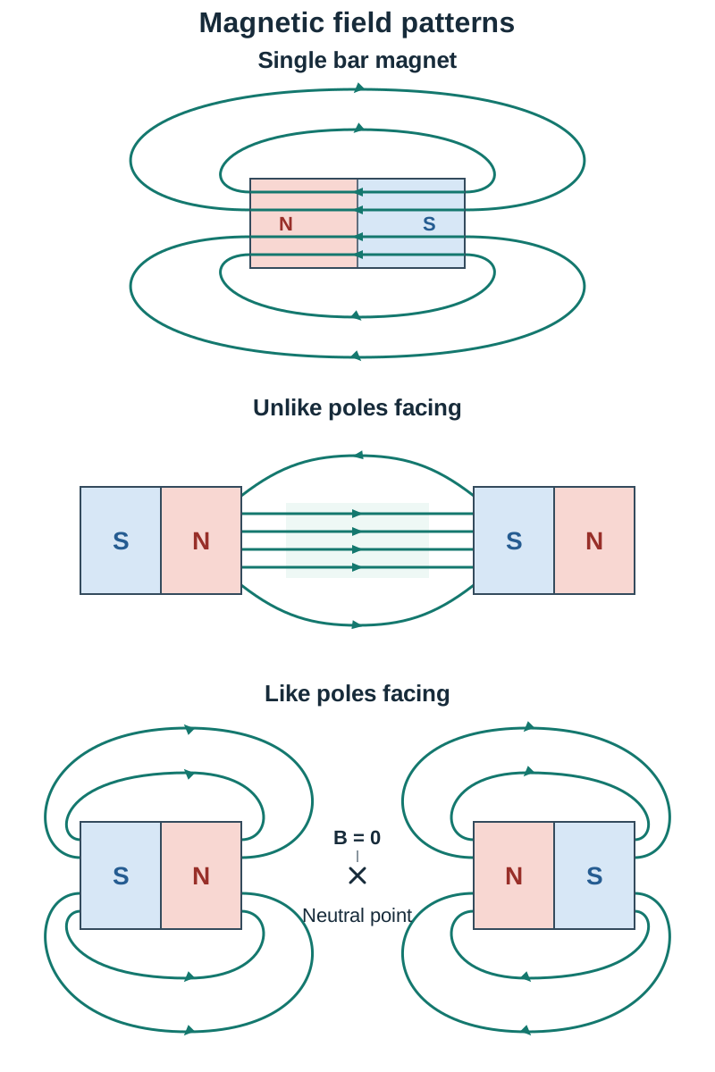
You can plot field lines using a small plotting compass. Place a bar magnet on a sheet of paper, set the compass near the north pole, and mark pencil dots at the needle's tip and tail. Move the tail to the second dot, mark the new tip position, and repeat until you trace a continuous curve into the south pole.
Magnetism can pass through non-magnetic materials, so a magnet can attract a paper clip through paper, wood, or aluminium.
| Magnet Type | Material Example | Retentivity (Holds Magnetism) | Common Practical Use |
|---|---|---|---|
| Permanent Magnet | Hard magnetic material (e.g. steel, alnico) | High (remains magnetised after field is removed) | Compass needles, fridge catches, loudspeakers |
| Temporary Magnet | Soft magnetic material (e.g. soft iron) | Low (demagnetises almost instantly when field is removed) | Electromagnet cores, relays, transformer cores |
Magnetic Effect of an Electric Current and Solenoids
In 1820, Hans Christian Oersted showed that an electric current produces a magnetic field when he noticed that a current-carrying wire deflected a nearby compass needle. When direct current flows through a conductor, it generates a magnetic field around it.
Field Around a Straight Wire
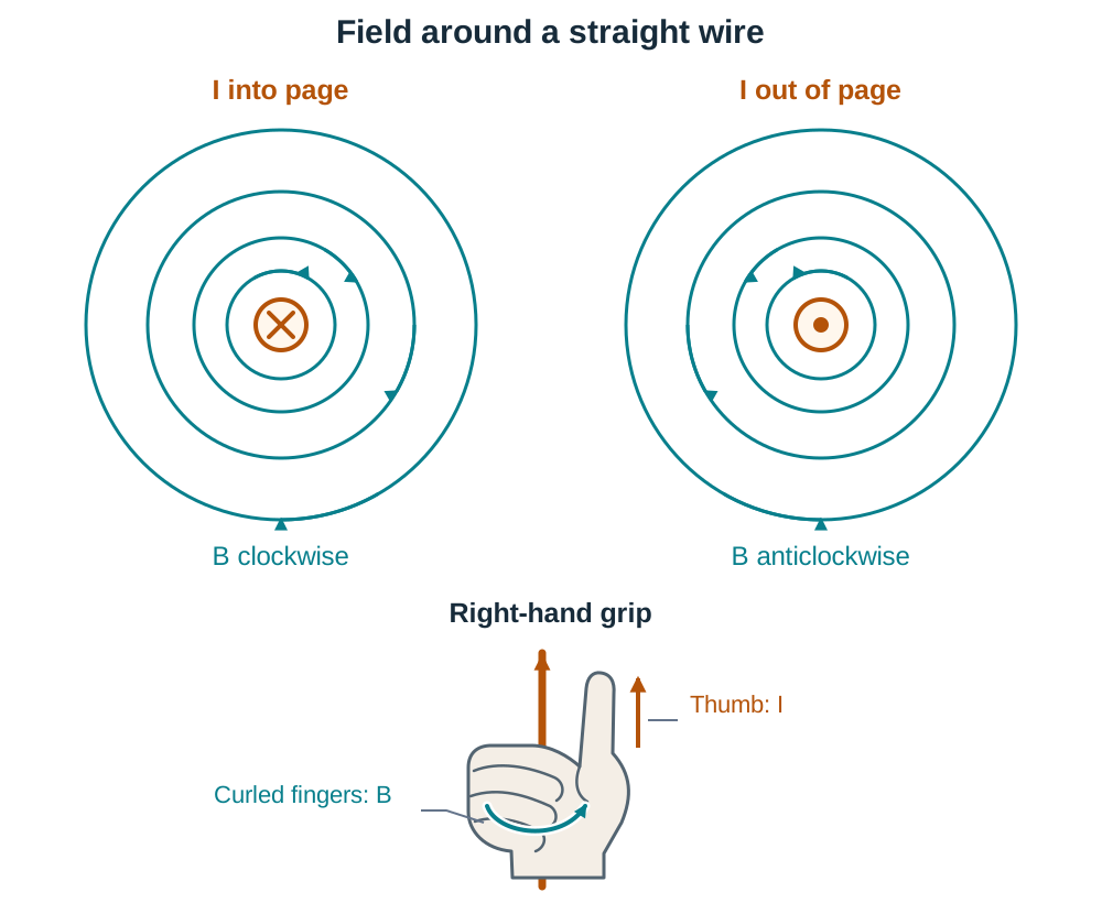
For a straight wire seen end-on, the field lines form concentric circles centred on the wire. Space the circles further apart as you move outward, because the field gets weaker further from the wire. Current into the page is represented by (like the tail feathers of an arrow moving away) and produces clockwise circles. Current out of the page is represented by (the tip of an oncoming arrow) and produces anticlockwise circles.
To find the direction, use the right-hand grip rule for a straight wire: grip the wire with your right hand with your thumb pointing in the direction of conventional current (positive to negative); your curled fingers point in the direction of the concentric magnetic field lines.
Solenoids and Finding Their Polarity
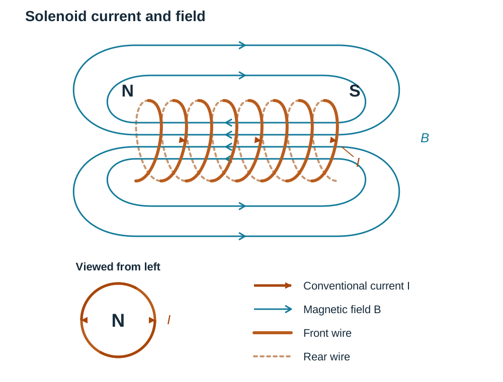
A solenoid is a long helical coil of wire whose length is greater than its diameter. When current passes through the turns, their individual fields combine. Inside the solenoid, draw parallel, evenly spaced lines along its axis, showing a strong, uniform magnetic field. Outside, the pattern is identical to that of a bar magnet, with lines looping from the north end to the south end.
Right-hand grip rule for a solenoid: Grip the solenoid with your right hand so that your fingers curl round the coil in the direction of the conventional current flowing through the turns. Your thumb then points towards the north pole of the solenoid.
End-view check: Look directly at one open end of the coil:
- If the current flows anticlockwise, that end is a north pole (picture an 'N' with arrows on its tips pointing anticlockwise).
- If the current flows clockwise, that end is a south pole (picture an 'S' with arrows on its tips pointing clockwise).
For example, if current enters the left-hand end of a solenoid and flows up the front face of each turn, curl your right fingers up over the front of the coil. Your thumb points to the left, so the left end is a north pole and the right end is a south pole.
Electromagnets and Domains
Iron is made of tiny microscopic regions called domains, each acting like a tiny magnet. Normally, these domains point in random directions, cancelling each other out. In an external magnetic field, the domains line up, turning the iron into a strong magnet. Soft iron's domains return to random orientations as soon as the external field is removed, whereas steel's domains stay locked in alignment.
Inserting a soft-iron core inside a solenoid creates an electromagnet. The core aligns with the field, increasing the magnetic flux density substantially. Because soft iron has low magnetic retentivity, it loses virtually all its magnetism the moment the current is cut off. Because an electromagnet can be switched on and off, and its strength changed by changing the current, it is used in scrapyard cranes, relays, electric bells, and door locks.
The Motor Effect and Magnetic Flux Density
When a current-carrying conductor is placed inside an external magnetic field, the field around the conductor interacts with the external field. This produces a mechanical force on the conductor, known as the motor effect.
The force is greatest when the wire is perpendicular to the magnetic field lines. If the wire runs parallel to the field lines, the force is zero.
Fleming's Left-Hand Rule
Hold your left hand with your thumb, first finger, and second finger mutually at right angles:
- First finger = Field ()
- seCond finger = Current (conventional current, )
- thuMb = Motion (direction of the resulting force)
Worked direction example: A horizontal wire carries current from left to right across a magnetic field directed vertically downwards (North pole above, South pole below). Point your first finger down and your second finger to the right. Your thumb points into the page, which is the direction of the force.
Defining Magnetic Flux Density ()
Magnetic flux density () at a point in a magnetic field is a vector quantity whose magnitude equals the force experienced per unit length by a straight conductor carrying unit current placed perpendicular to the field at that point:
When a conductor of length carrying current sits at right angles to a uniform magnetic field , the force is:
The SI unit of magnetic flux density is the tesla (T). The magnetic flux density is 1 tesla if a conductor of length carrying a current of at right angles to the field experiences a force of .
Using unit analysis (, so ):
Investigating the Force on a Current-Carrying Conductor (Higher Level)
This investigation examines how the electromagnetic force on a conductor relates to current and magnetic field.
Method and Variables
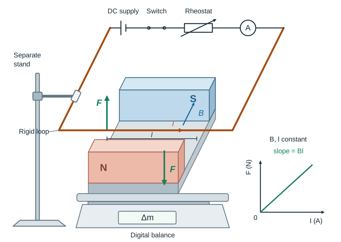
- Place a strong U-shaped magnet assembly on a digital top-pan balance and tare the reading to zero.
- Clamp a rigid horizontal wire loop from an external retort stand so that a section of length passes through the magnetic field between the poles without touching them.
- Connect the wire in series with a DC power supply, a rheostat, an ammeter, and a switch.
- Close the switch and record the current . By Newton's third law, if the magnetic field exerts an upward force on the wire, the wire exerts an equal downward reaction force on the magnet assembly. The balance reading changes by (up or down, depending on current direction).
- Calculate the electromagnetic force using , where is converted from grams to kilograms () and .
Investigating the Relationships
- Force versus current (): Keep the magnetic field and conductor length constant. Vary the current using the rheostat. A plot of on the y-axis against on the x-axis gives a straight line through the origin, confirming . The slope of this line equals , so the magnetic flux density is .
- Force versus magnetic field (): Keep current and length constant. Vary by adding matched ceramic slab magnets to the yoke or using magnets of known flux density (measured using a Hall probe). Plotting against gives a straight line through the origin, confirming .
Precautions and Sources of Error
- Precautions: Zero (tare) the balance before each run; verify that the wire does not touch the magnets; switch off current between readings so the wire does not heat up; read the balance quickly and steadily.
- Sources of error: Limited balance resolution for small force values; wire heating, which changes resistance and causes current to drift; edge effects (the magnetic field not being entirely uniform at the magnet ends); uncertainty in measuring the exact length of wire inside the field.
The Direct Current (DC) Motor
A direct current motor converts electrical energy into rotational kinetic energy using the motor effect. Some energy is inevitably lost as heat in the copper coils () and as friction at the brushes and axle bearings.
Visual Arrangement and Drawing Guide
To draw a simple DC motor:
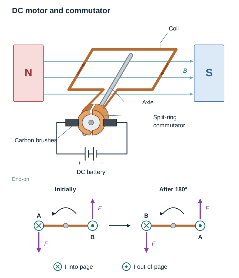
- Draw two magnetic poles facing each other: North on the left and South on the right, providing a horizontal magnetic field from left to right.
- Place a rectangular armature coil horizontally between the poles on a central axle.
- Connect the ends of the coil to a split-ring commutator on the axle: two semi-cylindrical copper segments separated by a small insulating gap.
- Draw two carbon (graphite) brushes pressing lightly against the outside of the split ring, connected to a DC battery.
- Label the current directions: into the page on one side of the coil, out of the page on the other.
Principle of Operation and Couple
Current travels in opposite directions along the two sides of the coil perpendicular to the field. By Fleming's left-hand rule, one side experiences an upward force and the opposite side experiences an equal downward force (). These two forces are equal in size, opposite in direction, and act along different lines, so they form a couple: a pair of forces that turns an object without moving it along. The couple turns the coil about its axle.
Role of the Split-Ring Commutator
When the coil reaches the vertical position, its plane is perpendicular to the field lines. Here, the couple forces pull directly outwards in line with the coil, so the turning effect drops to zero. The coil's momentum (its inertia) carries it just past this vertical position.
At this instant, each half of the split ring breaks contact with one brush and reconnects with the opposite brush. This reverses the direction of the current in each side of the coil every half-turn (). Because the current reverses relative to the fixed magnetic field, the upward and downward forces switch sides, sustaining continuous rotation in one direction rather than oscillating back and forth.
Factors Increasing Motor Speed and Turning Effect
From , the turning effect and rotational speed of a DC motor can be increased by:
- Increasing the current () in the coil.
- Using stronger permanent magnets or electromagnets (increasing ).
- Increasing the number of turns () on the coil, as each turn adds an extra pair of forces.
- Increasing the area of the coil or length () of the sides in the field.
- Winding the coil around a soft-iron armature core to concentrate the magnetic flux.
Moving Charges, Beam Deflection, and Parallel Conductors
An electric current is a flow of charge. Because a current-carrying wire experiences a force in a magnetic field, individual free moving charges must also experience a deflecting force.
Derivation of
For a charge moving with speed at right angles to a uniform magnetic field :
- Start with the force on a conductor: .
- Electric current is charge per unit time: , so .
- In time , the charge travels the length , so .
- Therefore, the force on a single moving charge is:
When applying Fleming's left-hand rule to moving charges, remember that the second finger points along conventional current:
- For a positive charge (e.g. a proton), current points in the direction of velocity .
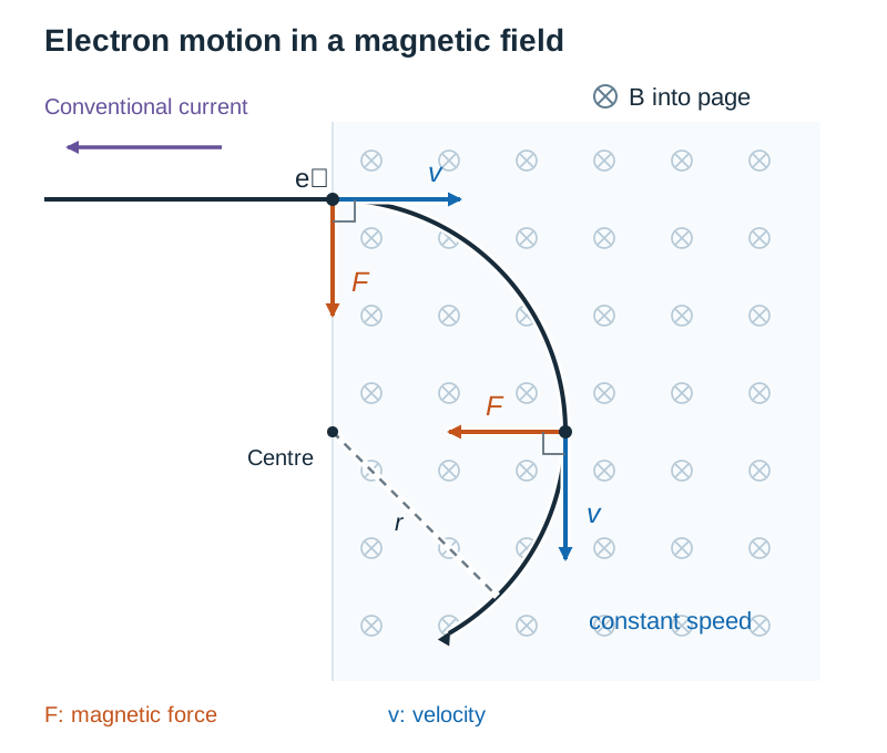
- For a negative charge (e.g. an electron beam), conventional current points opposite to the electron velocity vector.
An electron beam entering a uniform magnetic field perpendicularly is deflected into a circular arc. Because the magnetic force acts at right angles to velocity at every instant, it does no work on the charge (). The particle's speed and kinetic energy remain constant, but its direction changes continuously.
The magnetic force provides the required centripetal force:
Faster or heavier particles follow larger circular paths, while stronger fields or larger charges produce tighter curves.
Forces Between Parallel Conductors
Two long parallel wires carrying currents exert magnetic forces on each other because each sits inside the magnetic field produced by the other:
- Currents in the same direction attract.
- Currents in opposite directions repel.
Historically (before the 2019 SI redefinition), the ampere was defined using this mutual force: the constant current which, maintained in two straight parallel conductors of infinite length and negligible cross-section placed 1 metre apart in a vacuum, produces a force of per metre between them. Today, the ampere is defined by fixing the numerical value of the elementary charge .
Everyday Applications of Permanent and Temporary Magnets
Permanent magnets and electromagnets are used across domestic, medical, and industrial technologies. For each application, be able to identify which type of magnet is used and why:
- Scrapyard Cranes (Temporary Magnet): Heavy lifting cranes use large electromagnets with soft-iron cores. When the operator switches on a large direct current, the electromagnet generates an intense magnetic field that lifts tonnes of scrap iron and steel. Once positioned over a container, the operator switches off the current; the soft iron immediately demagnetises and drops the load.
- Moving-Coil Loudspeakers (Permanent Magnet and Electromagnet): An audio amplifier feeds an alternating current signal into a small cylindrical coil (the voice coil), which is attached to a paper or plastic speaker cone. The voice coil sits inside the radial magnetic field of a strong permanent magnet. As alternating current flows through the coil, it experiences an alternating force () that drives the cone rapidly back and forth, generating sound waves in the air.
- Magnetic Levitation / Maglev (Electromagnets): Maglev trains use powerful electromagnets on the train and guideway to lift the carriage a small distance above the track. Opposing magnetic forces levitate the vehicle, while travelling magnetic fields propel it forward. Because there is no mechanical wheel-rail contact, rolling friction is eliminated, drastically reducing mechanical wear and allowing high operating speeds (though air resistance still opposes motion).
- Magnetic Resonance Imaging / MRI (Superconducting Electromagnet): Diagnostic scanners use a powerful, liquid-helium-cooled superconducting electromagnet to produce an intense, uniform magnetic field (typically 1.5 to 3.0 T). This field aligns protons in body tissues without using ionising radiation. Radio pulses disturb this alignment, and the emitted radio signals are processed into high-resolution soft-tissue scans.
Key terms
- Magnetic field
- Any region of space where a magnetic force can be detected.
- Magnetic field line
- An imaginary line drawn such that the tangent to it at any point indicates the direction of the magnetic field vector at that point, running from north to south externally.
- Neutral point
- A point in a resultant magnetic field where opposing magnetic fields cancel out, giving zero magnetic force.
- Ferromagnetic material
- A material such as iron, steel, nickel, or cobalt that is strongly attracted to magnets and can be magnetised.
- Solenoid
- A long helical coil of wire whose length is greater than its diameter, producing a uniform magnetic field along its interior when carrying current.
- Motor effect
- The mechanical force experienced by a current-carrying conductor when placed inside an external magnetic field.
- Fleming's left-hand rule
- A rule for finding the force direction on a conductor: first finger points along the magnetic field, second finger along conventional current, and thumb along the resulting motion or force.
- Magnetic flux density (B)
- A vector quantity whose magnitude equals the force experienced per unit length by a straight conductor carrying unit current placed perpendicular to the field at that point.
- Tesla (T)
- The SI unit of magnetic flux density; one tesla is the flux density when a conductor of length 1 metre carrying a current of 1 ampere perpendicular to the field experiences a force of 1 newton.
- Split-ring commutator
- A segmented conductive copper ring in a DC motor that reverses the direction of current in the rotating coil every half-turn to maintain continuous unidirectional torque.
- Couple
- A pair of equal and opposite parallel forces whose lines of action do not coincide, producing rotation without linear translation.
Check yourself
What is the direction of magnetic field lines outside a bar magnet?
Field lines emerge from the north pole and enter the south pole, forming continuous closed loops.
Looking directly at the end of a solenoid, the conventional current flows anticlockwise. Is that end a north or south pole?
It is a north pole (anticlockwise current corresponds to an N pole).
Why does the magnetic force do zero work on a charged particle moving through a magnetic field?
The force acts at right angles (90°) to the velocity at every instant. Since work done is W = F s cos(90°) = 0, speed and kinetic energy remain constant.
What is the role of the split-ring commutator in a direct current motor?
It reverses the current direction through the coil every half-turn (180°), ensuring that the couple continues turning the coil in the same rotational direction.
State two ways to increase the rotational speed of a DC motor.
Increase the current in the coil; use stronger magnets (increase B); or increase the number of turns on the armature coil.
In a nuclear detector, a proton (charge 1.6 × 10⁻¹⁹ C, mass 1.67 × 10⁻²⁷ kg) enters a magnetic field of 0.50 T at right angles and follows a circle of radius 2.3 mm. What is the speed of the proton?
Using v = (q B r) / m, substitute q = 1.6 × 10⁻¹⁹ C, B = 0.50 T, r = 2.3 × 10⁻³ m, and m = 1.67 × 10⁻²⁷ kg to get v ≈ 1.1 × 10⁵ m s⁻¹.