

Basic Electronics, Logic Gates, and Binary Rationale
Electrical Fundamentals and Ohm's Law
Digital computing relies on fundamental electrical quantities:
- Voltage (): The electrical potential difference driving electric charge through a circuit, measured in volts (V).
- Current (): The rate of flow of electric charge, measured in amperes (A).
- Resistance (): The opposition to the flow of electric current, measured in ohms (). Resistors limit current to protect delicate electronic components, such as LEDs.
- Ohm's Law: Relates these three properties: . For instance, if an LED circuit runs on a supply and must not exceed () of current, the required resistance is .
- Capacitors: Store and release electrical charge to smooth out voltage spikes and build dynamic memory cells.
- Transistors: Microscopic semiconductor switches. Applying a voltage to the control gate allows current to pass (switch ON); removing the voltage stops current flow (switch OFF).
Why Computers Use Binary
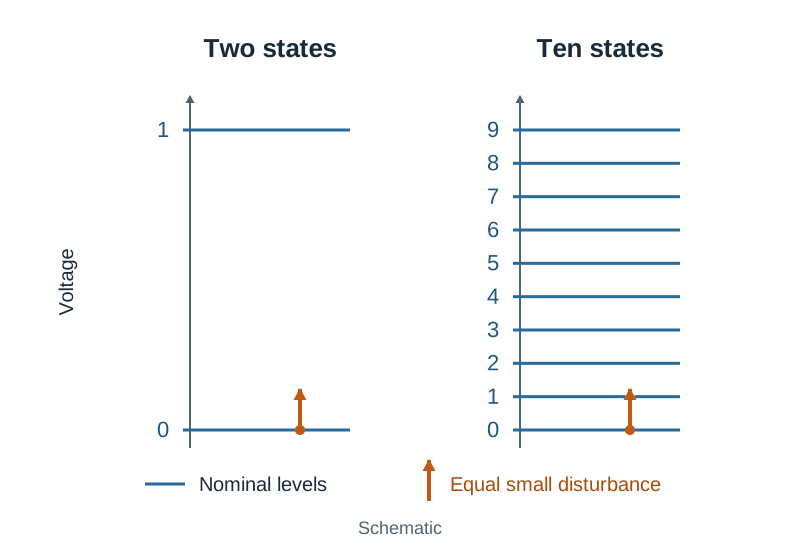
Computers use binary (bits 0 and 1) because electronic circuits function most reliably with two distinct physical states: high voltage (such as or representing 1) and low voltage ( representing 0).
If a circuit had to differentiate between ten discrete voltage levels (one for each decimal digit), the margins between levels would be very narrow. Slight electrical noise, heat fluctuations, or component aging would easily cause one level to be misread as another. With only two states, there is a wide voltage margin, ensuring small electrical variations do not flip a 1 into a 0.
Logic Gates and Truth Tables
Transistors are combined to build logic gates, which evaluate Boolean logic rules:
| Input | Input | NOT | AND () | OR () | NAND () | NOR () | XOR () |
|---|---|---|---|---|---|---|---|
| 0 | 0 | 1 | 0 | 0 | 1 | 1 | 0 |
| 0 | 1 | 1 | 0 | 1 | 1 | 0 | 1 |
| 1 | 0 | 0 | 0 | 1 | 1 | 0 | 1 |
| 1 | 1 | 0 | 1 | 1 | 0 | 0 | 0 |
- NOT: Inverts the single input bit.
- AND: Outputs
1only when both inputs are1. - OR: Outputs
1when one or both inputs are1. - NAND: Outputs
0only when both inputs are1(inverse of AND). - NOR: Outputs
1only when both inputs are0(inverse of OR). - XOR: Outputs
1when inputs differ; outputs0when they match.
Combinational Circuits: The Half-Adder and Full Adder
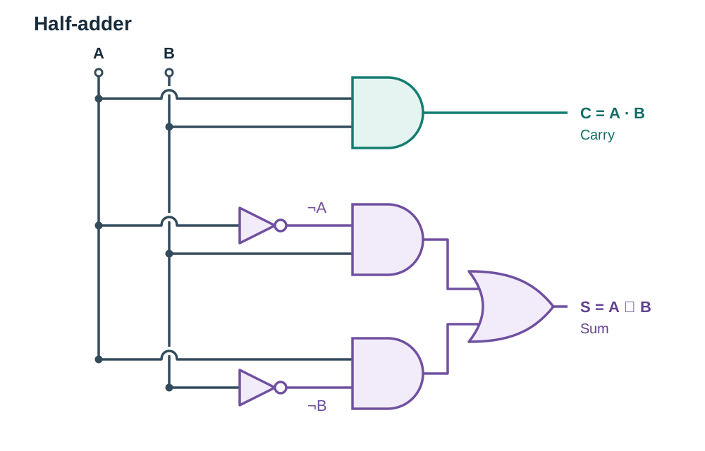
A half-adder sums two 1-bit binary inputs ( and ) to produce a Sum () and a Carry ():
- Carry ():
- Sum ():
When and , binary addition gives , giving and . Two half-adders combined with an OR gate form a full adder, which accepts an additional carry-in bit so multi-bit numbers can be added together.
Multi-Input Logic Circuit Truth Table
To build a truth table for an unfamiliar combinational circuit, list all combinations of the inputs in binary order, add columns for intermediate gates, and determine the final output.
For the circuit :
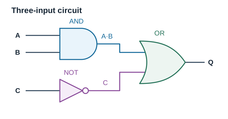
| 0 | 0 | 0 | 0 | 1 | 1 |
| 0 | 0 | 1 | 0 | 0 | 0 |
| 0 | 1 | 0 | 0 | 1 | 1 |
| 0 | 1 | 1 | 0 | 0 | 0 |
| 1 | 0 | 0 | 0 | 1 | 1 |
| 1 | 0 | 1 | 0 | 0 | 0 |
| 1 | 1 | 0 | 1 | 1 | 1 |
| 1 | 1 | 1 | 1 | 0 | 1 |