

A computer system combines hardware, software, communications, and users to process data and solve problems. Modern computing is built on the von Neumann architecture, in which program instructions and data share primary memory and are fetched, decoded, and executed sequentially by the Central Processing Unit (CPU). At the physical level, electronic components such as transistors operate as binary switches based on electrical voltage. Higher layers—including the operating system, network protocols such as TCP/IP, and application software—abstract this hardware into functional systems.
Hardware, Software, and the Four-Layer Model
A computer system relies on both physical equipment and intangible instructions to operate.
Hardware and Software
- Hardware refers to the physical parts of a computer system that you can touch. Examples include the CPU, RAM, hard disk drives, solid-state drives, keyboards, and monitors.
- Software refers to the programs, applications, and instructions that tell the hardware what to do. Software cannot be physically touched.
- System software manages and runs the computer hardware itself. Examples include operating systems such as Windows, macOS, and Linux, as well as utility programs and device drivers.
- Application software allows the end user to perform specific productive or recreational tasks. Examples include web browsers, word processors, and games.
The Four-Layer Computing Model
Computer systems use layered abstraction so users and software can interact with hardware without needing to manipulate physical circuitry directly:
- User: Interacts with software using graphical user interfaces (GUIs), touchscreen displays, or command-line interfaces.
- Application Layer: Software programs running tasks on behalf of the user.
- Operating System Layer: System software that manages system resources, handles input/output hardware, and provides a platform for applications.
- Hardware Layer: Physical electronic devices—CPU, memory, storage, and peripheral controllers.
Core Roles of the Operating System
- Processor Management: Allocates CPU time among running processes using scheduling algorithms and handles interrupts to maintain smooth multitasking.
- Memory Management: Allocates memory addresses to open programs so they do not overwrite each other's data, and uses virtual memory on secondary storage when RAM becomes full.
- File System Management: Organises data into hierarchical folders and files, keeps track of storage locations, and manages access permissions.
- Device Management: Uses device drivers to translate high-level operating system commands into specific hardware signals for peripherals.
- Security and User Authentication: Controls access to the computer using user accounts, passwords, and file permission settings.
The von Neumann Architecture and the Fetch-Decode-Execute Cycle
Most general-purpose computers follow the von Neumann architecture. Its key principle is that program instructions and data share the same main memory and communication buses, rather than being kept in separate storage units.
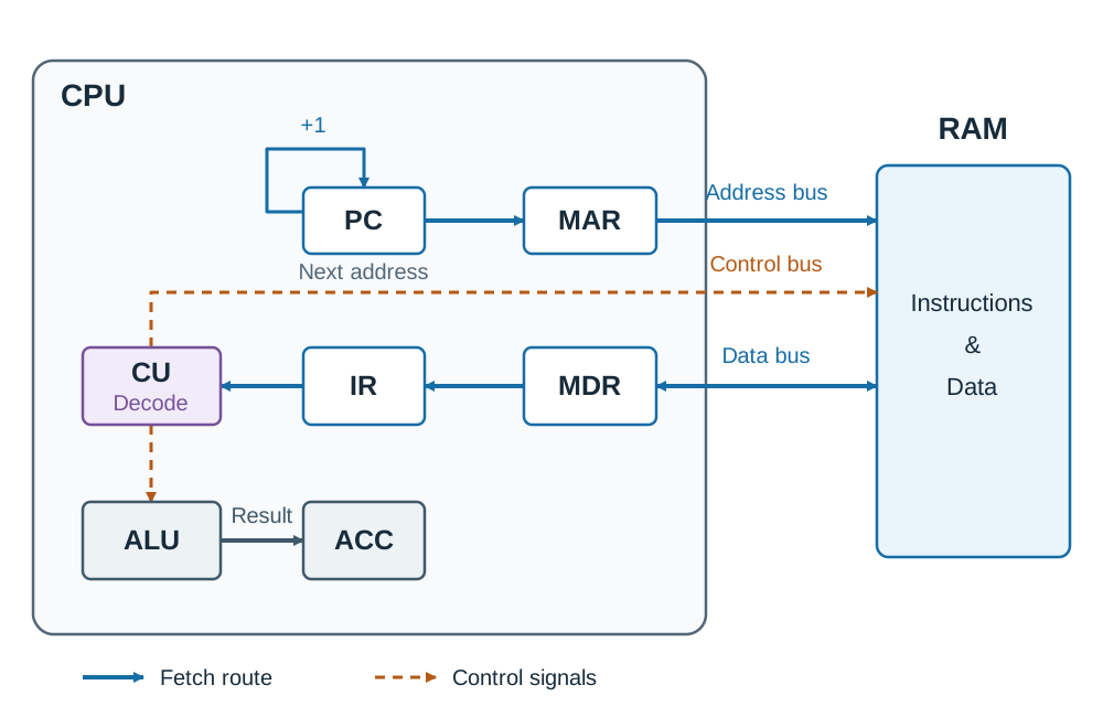
The Central Processing Unit (CPU) fetches, decodes, and executes instructions. It contains three primary components:
- Control Unit (CU): Manages the execution of instructions. It directs the flow of data within the CPU, coordinates hardware signals, and decodes instruction opcodes.
- Arithmetic Logic Unit (ALU): Carries out arithmetic calculations (such as addition and subtraction) and logical evaluations (
AND,OR,NOT, and comparisons like<,>). - Registers: Very fast, very small storage locations inside the CPU itself. Key registers include:
- Program Counter (PC): Holds the memory address of the next instruction waiting to be fetched.
- Memory Address Register (MAR): Holds the physical memory address currently being read from or written to.
- Memory Data Register (MDR): Holds the data value or instruction just fetched from memory, or waiting to be written to memory.
- Instruction Register (IR): Holds the instruction currently being decoded by the CU.
- Accumulator (ACC): Holds intermediate calculation results produced by the ALU.
The Fetch-Decode-Execute (FDE) Cycle
The CPU runs instructions in a continuous cycle:
- Fetch: The memory address in the PC is copied into the MAR. The CU sends a read signal to RAM along the control bus. The instruction at that memory address is returned via the data bus into the MDR, and then copied into the IR. The PC increments immediately to hold the address of the next instruction in sequence.
- Decode: The CU decodes the opcode in the IR to determine what operation must occur and what data operands are needed.
- Execute: The CU directs the necessary components to complete the task. If mathematical or logical operations are required, the ALU processes them and stores the result in the Accumulator. If data must be saved to RAM, it is sent via the MDR.
Tracing the FDE Cycle with a Simple Program
Consider a program with instructions at three sequential memory addresses: address 0 holds LOAD 5, address 1 holds ADD 6, and address 2 holds STORE 7. In RAM, memory address 5 contains the value 12, and address 6 contains the value 30.
| Cycle Step | PC | MAR | MDR | IR | ACC | Explanation |
|---|---|---|---|---|---|---|
| Start | 0 | - | - | - | 0 | CPU begins at instruction address 0. |
| Fetch 1 | 1 | 0 | LOAD 5 | LOAD 5 | 0 | Address 0 is fetched; PC increments to 1. |
| Execute 1 | 1 | 5 | 12 | LOAD 5 | 12 | Contents of address 5 (12) are loaded into ACC. |
| Fetch 2 | 2 | 1 | ADD 6 | ADD 6 | 12 | Address 1 is fetched; PC increments to 2. |
| Execute 2 | 2 | 6 | 30 | ADD 6 | 42 | ALU adds contents of address 6 (30) to ACC (12 + 30 = 42). |
| Fetch 3 | 3 | 2 | STORE 7 | STORE 7 | 42 | Address 2 is fetched; PC increments to 3. |
| Execute 3 | 3 | 7 | 42 | STORE 7 | 42 | ACC value (42) is written to memory address 7 via the MDR. |
Processor Performance and Memory Hierarchy
Factors Influencing Processor Performance
- Clock Speed: The number of electrical pulses the CPU clock generates per second, measured in hertz (Hz). A 3 GHz processor completes three billion clock cycles each second. A higher clock speed allows more instructions to be executed per second, provided the CPU is not stalled waiting for memory.
- Cache: A small bank of high-speed memory located directly on or beside the CPU core that stores frequently accessed instructions and data. A larger cache means the CPU finds more of its required data close by, reducing time spent waiting for slower RAM.
- Number of Cores: A core is an independent processing unit containing its own CU, ALU, and registers. Multiple cores allow parallel processing of separate instruction streams, but overall performance doubles only if software is specifically written to divide its workload across multiple threads.
Memory and Storage Hierarchy
Computer memory balances access speed, capacity, and cost per unit.
| Level | Volatility | Location | Speed | Purpose |
|---|---|---|---|---|
| Registers | Volatile | Inside the CPU | Fastest | Holds immediate operands, addresses, and calculation values |
| Cache | Volatile | Next to the CPU core | Very fast | Holds frequently repeated loop instructions and active data |
| RAM | Volatile | Main system board | Fast | Holds operating system files and active programs currently running |
| ROM | Non-volatile | System board chip | Moderate | Holds permanent startup instructions (BIOS/UEFI bootstrap loader) |
| Secondary Storage | Non-volatile | Drive bay / internal bus | Slower | Provides long-term persistent storage for files, applications, and the OS |
Primary Memory: RAM vs ROM
- Random Access Memory (RAM): The computer's main working memory. The CPU can read from and write to any location directly in any order. It is volatile, meaning all stored data is erased when power is lost.
- Read-Only Memory (ROM): Memory that can be read by the CPU but cannot be altered during standard operation. It is non-volatile, retaining its contents permanently without electrical power. It stores the bootstrap loader used to start the computer.
Secondary Storage: SSD vs HDD
Because RAM loses its data on shutdown, non-volatile secondary storage is required for long-term file retention:
- Solid-State Drives (SSDs): Store data electronically using flash memory chips with no moving parts. They offer faster read/write speeds, lower power consumption, and greater resistance to physical shocks.
- Hard Disk Drives (HDDs): Store data magnetically on rotating platters read by moving mechanical heads. They offer a lower cost per gigabyte for high capacities but operate much more slowly and are sensitive to physical impacts.
Basic Electronics, Logic Gates, and Binary Rationale
Electrical Fundamentals and Ohm's Law
Digital computing relies on fundamental electrical quantities:
- Voltage (): The electrical potential difference driving electric charge through a circuit, measured in volts (V).
- Current (): The rate of flow of electric charge, measured in amperes (A).
- Resistance (): The opposition to the flow of electric current, measured in ohms (). Resistors limit current to protect delicate electronic components, such as LEDs.
- Ohm's Law: Relates these three properties: . For instance, if an LED circuit runs on a supply and must not exceed () of current, the required resistance is .
- Capacitors: Store and release electrical charge to smooth out voltage spikes and build dynamic memory cells.
- Transistors: Microscopic semiconductor switches. Applying a voltage to the control gate allows current to pass (switch ON); removing the voltage stops current flow (switch OFF).
Why Computers Use Binary
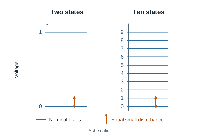
Computers use binary (bits 0 and 1) because electronic circuits function most reliably with two distinct physical states: high voltage (such as or representing 1) and low voltage ( representing 0).
If a circuit had to differentiate between ten discrete voltage levels (one for each decimal digit), the margins between levels would be very narrow. Slight electrical noise, heat fluctuations, or component aging would easily cause one level to be misread as another. With only two states, there is a wide voltage margin, ensuring small electrical variations do not flip a 1 into a 0.
Logic Gates and Truth Tables
Transistors are combined to build logic gates, which evaluate Boolean logic rules:
| Input | Input | NOT | AND () | OR () | NAND () | NOR () | XOR () |
|---|---|---|---|---|---|---|---|
| 0 | 0 | 1 | 0 | 0 | 1 | 1 | 0 |
| 0 | 1 | 1 | 0 | 1 | 1 | 0 | 1 |
| 1 | 0 | 0 | 0 | 1 | 1 | 0 | 1 |
| 1 | 1 | 0 | 1 | 1 | 0 | 0 | 0 |
- NOT: Inverts the single input bit.
- AND: Outputs
1only when both inputs are1. - OR: Outputs
1when one or both inputs are1. - NAND: Outputs
0only when both inputs are1(inverse of AND). - NOR: Outputs
1only when both inputs are0(inverse of OR). - XOR: Outputs
1when inputs differ; outputs0when they match.
Combinational Circuits: The Half-Adder and Full Adder
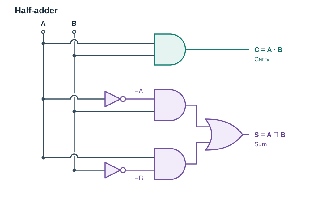
A half-adder sums two 1-bit binary inputs ( and ) to produce a Sum () and a Carry ():
- Carry ():
- Sum ():
When and , binary addition gives , giving and . Two half-adders combined with an OR gate form a full adder, which accepts an additional carry-in bit so multi-bit numbers can be added together.
Multi-Input Logic Circuit Truth Table
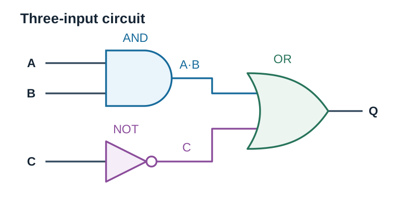
To build a truth table for an unfamiliar combinational circuit, list all combinations of the inputs in binary order, add columns for intermediate gates, and determine the final output.
For the circuit :
| 0 | 0 | 0 | 0 | 1 | 1 |
| 0 | 0 | 1 | 0 | 0 | 0 |
| 0 | 1 | 0 | 0 | 1 | 1 |
| 0 | 1 | 1 | 0 | 0 | 0 |
| 1 | 0 | 0 | 0 | 1 | 1 |
| 1 | 0 | 1 | 0 | 0 | 0 |
| 1 | 1 | 0 | 1 | 1 | 1 |
| 1 | 1 | 1 | 1 | 0 | 1 |
Number Systems: Binary, Decimal, and Hexadecimal Conversions
While computers store and compute entirely in binary, programmers often write values in hexadecimal (base 16) because it is much more compact. One hexadecimal digit represents a 4-bit binary group (a nibble). This makes values easier to read, quicker to write, and less prone to manual transcription errors. Hexadecimal is widely used for RGB colour codes (such as #FF0000 for red), MAC addresses, and memory locations.
Hexadecimal uses digits 0–9 and letters A–F, where .
1. Decimal to Binary
Repeatedly divide the decimal number by 2 and note the integer remainders. Read the remainders from bottom to top (most significant bit to least significant bit).
Example: Convert to binary:
Reading bottom to top gives (or padded to an 8-bit byte: 00110101).
2. Binary to Hexadecimal
Group the bits into sets of four starting from the right (least significant bit). Pad the leftmost group with leading zeros if it has fewer than four bits. Convert each nibble into its hexadecimal character.
Example: Convert to hexadecimal:
- Split into nibbles:
1101and1011 - Left nibble:
- Right nibble:
- Result:
3. Hexadecimal to Binary
Replace each hexadecimal character with its direct 4-bit binary equivalent.
Example: Convert to binary:
- Combine the nibbles:
4. Hexadecimal to Decimal
Multiply each digit by its power of 16 () from right to left and add the products.
Example: Convert to decimal:
5. Decimal to Hexadecimal
Divide the decimal number by 16 repeatedly, writing remainders in hex notation from bottom to top.
Example: Convert to hexadecimal:
- remainder ()
- remainder ()
- Result:
Inputs, Embedded Systems, and Automation
Analogue vs Digital Inputs
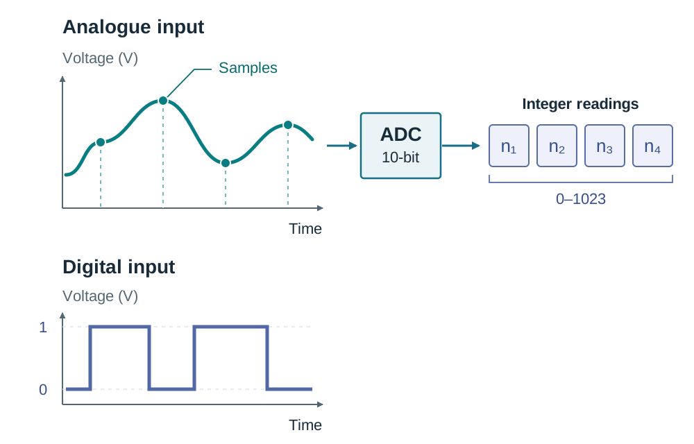
- Digital Inputs: Electrical signals that exist in only one of two discrete states—completely ON (
1, typically 3.3 V or 5 V) or completely OFF (0, 0 V). Examples include push buttons, switches, and digital motion sensors. - Analogue Inputs: Signals that vary continuously over time across an electrical range. Examples include light-dependent resistors (light level), thermistors (temperature), and potentiometers (rotational angle).
Because microprocessors operate only on binary numbers, an Analogue-to-Digital Converter (ADC) must sample the continuous analogue voltage and convert it into a discrete digital integer (such as 0 to 1023 for a 10-bit converter).
Embedded Systems
An embedded system is a dedicated computer built into a larger mechanical or electrical system to perform a specific dedicated control function. Examples include domestic washing machines, automotive anti-lock braking systems (ABS), and smart thermostats. They rely on microcontrollers integrating a CPU, memory, and programmable input/output pins on a single chip, built for low power draw and automated operation.
Automated Embedded Program (MicroPython)
In the Applied Learning Task 4 context, students use embedded code to read sensor data, store values, and control outputs automatically. The BBC micro:bit MicroPython module uses read_analog() (using the American spelling in code) to read pin voltages between 0 and 1023.
from microbit import *

readings = []                       # list to store analogue data
for i in range(10):
    level = pin1.read_analog()      # analogue input: reads 0 to 1023
    readings.append(level)          # store the reading
    sleep(1000)                     # wait 1 second between samples

average = sum(readings) / len(readings)

if average < 300:                   # threshold check for dark conditions
    pin0.write_digital(1)           # digital output: turn LED on
else:
    pin0.write_digital(0)           # digital output: turn LED off
Execution Trace: If the ten recorded readings are [250, 260, 240, 255, 245, 250, 260, 240, 250, 250], their sum is 2500 and the average is . Because , pin 0 outputs a high voltage (1) and turns on the LED without human intervention.
Networks, the Internet, and Communication Protocols
The Internet vs The World Wide Web
These terms refer to distinct layers of computer networking:
- The Internet: The global physical infrastructure of interconnected networks, transmission cables (undersea fibre-optic cables, copper lines), routers, switches, servers, and user devices that transports raw data packets worldwide.
- The World Wide Web (WWW): A distributed information service running on top of the Internet infrastructure. It consists of hyperlinked multimedia documents and web applications accessed via a web browser using HTTP.
Key Network Hardware Components
- Server: A high-capacity computer that stores network resources (web pages, files, databases) and serves them to requesting clients.
- Client: A user device (such as a laptop or smartphone) that requests services or content from a server.
- Router: A networking device that inspects the destination IP address on incoming data packets and directs them across different networks towards their destination.
- Switch: A device that connects computers together within a single local area network (LAN), directing frames directly to the intended destination device using MAC addresses.
- Network Interface Card (NIC): Hardware inside a computer that allows it to transmit and receive data over a physical cable or wireless (Wi-Fi) signal.
The TCP/IP Protocol Model
Network communication is organised into four hierarchical layers. Data passes down these layers on the sending device and back up through them on the receiving device:
- Application Layer: Interacts directly with software applications. Protocols like HTTP create requests for web documents, while VoIP handles audio and video streaming data.
- Transport Layer (TCP): Manages end-to-end communication reliability. TCP divides outgoing data into numbered packets, checks packet integrity, requests retransmission of lost packets, and reassembles them in order on the receiving computer.
- Internet Layer (IP): Handles packet addressing and routing across networks. IP adds the sender's and receiver's source and destination IP addresses to each packet header so routers can navigate them across different networks.
- Link Layer (Network Access): Converts packets into physical electrical, optical, or radio signals and transmits them over the local physical medium (Ethernet cable, Wi-Fi, or fibre).
Tracing a Client-Server Request
- A user enters a web address into a browser on the client computer.
- The browser generates an HTTP request at the Application layer.
- TCP at the Transport layer splits the request into numbered packets.
- IP at the Internet layer attaches source and destination IP addresses to each packet.
- The Link layer transmits the electrical or radio signals onto the local connection.
- Routers inspect each packet's destination IP address and route it across the Internet to the target server.
- The web server processes the request and sends the webpage back as an HTTP response in packets.
- TCP on the client machine confirms all packets arrived, reassembles them in order, and the browser renders the webpage.
Internet Protocols: HTTP, TCP, IP, and VoIP
- HTTP (Hypertext Transfer Protocol): An application layer protocol used by web browsers to request and receive web pages. HTTPS adds encryption, ensuring that intercepted packets cannot be read or altered.
- TCP (Transmission Control Protocol): Guarantees reliable, ordered delivery of data by requiring acknowledgements and retransmitting lost packets.
- IP (Internet Protocol): Directs packets across network boundaries using numerical IP addresses.
- VoIP (Voice over Internet Protocol): Transmits digitised voice calls over IP networks. Unlike TCP-based file transfers, VoIP prioritises real-time speed over absolute delivery perfection; dropped packets are skipped rather than retransmitted to prevent audible audio lag.
Key terms
- Hardware
- The physical, tangible components of a computer system, such as the CPU, RAM, storage drives, and input/output devices.
- Software
- The intangible programs, data, and instructions that control computer hardware and direct its operations.
- System Software
- Programs designed to run and manage computer hardware directly, including operating systems, device drivers, and maintenance utilities.
- Application Software
- Programs designed to help the user perform specific tasks, such as web browsers, spreadsheets, and games.
- Von Neumann Architecture
- A computer design in which program instructions and data share the same main memory and are fetched, decoded, and executed sequentially by the CPU.
- Control Unit (CU)
- The CPU component that directs instruction execution, coordinates the movement of data, and decodes instruction opcodes.
- Arithmetic Logic Unit (ALU)
- The CPU component that performs arithmetic operations (addition, subtraction) and Boolean logical operations.
- Program Counter (PC)
- A CPU register that stores the memory address of the next instruction waiting to be fetched from primary memory.
- Accumulator (ACC)
- A CPU register that temporarily holds intermediate arithmetic and logical results produced by the ALU.
- RAM
- Random Access Memory; fast, volatile main working memory directly accessible by the CPU to read and write active programs and data.
- ROM
- Read-Only Memory; non-volatile primary memory holding permanent startup instructions (BIOS/firmware) that cannot be modified during normal operation.
- Cache
- Small, high-speed volatile memory located on or close to the CPU that stores frequently accessed instructions and data to reduce latency.
- Clock Speed
- The frequency of electrical pulses generated by the CPU clock oscillator, measured in hertz (Hz), which governs the timing of instruction execution.
- Transistor
- A semiconductor component acting as an electronically controlled switch, turning current on or off to represent binary 1 and 0.
- Logic Gate
- A basic electronic circuit formed from transistors that takes one or more binary inputs and outputs a binary signal based on a Boolean rule.
- Nibble
- A group of four binary bits, represented by a single hexadecimal character.
- Embedded System
- A dedicated computer system built into a larger machine or device to perform a specific dedicated control task.
- Analogue-to-Digital Converter (ADC)
- An electronic circuit that samples continuous analogue sensor voltages and converts them into discrete binary numbers for a processor.
- The Internet
- The global physical infrastructure of interconnected computer networks, cables, routers, switches, and servers.
- World Wide Web (WWW)
- An information service of hyperlinked web pages and multimedia documents running on top of the Internet infrastructure.
- Transmission Control Protocol (TCP)
- A transport layer protocol that splits data into packets, ensures reliable arrival, retransmits lost packets, and reorders them upon delivery.
- Internet Protocol (IP)
- A network layer protocol responsible for logical addressing and routing data packets across interconnected networks.
- Voice over Internet Protocol (VoIP)
- An application protocol that packetises and transmits real-time voice and video communication across IP networks.
Check yourself
Is a USB flash drive classified as hardware or software, and is a printer driver classified as system software or application software?
A USB flash drive is hardware (a physical storage device). A printer driver is system software (it enables the operating system to communicate with the hardware printer).
What happens to the Program Counter during the fetch stage of the FDE cycle?
The address in the PC is copied to the Memory Address Register (MAR), and the PC immediately increments to hold the memory address of the next sequential instruction.
Convert the hexadecimal number 2F to both decimal and 8-bit binary notation.
Decimal: (2 * 16) + 15 = 47. Binary: 2 = 0010 and F = 1111, giving 00101111.
Why does adding more CPU cores not automatically make every program run twice as fast?
Software must be specifically programmed to divide tasks across multiple threads. If an algorithm is sequential, other cores sit idle waiting for preceding steps to complete.
Name the four layers of the TCP/IP model in order from highest to lowest.
1. Application layer; 2. Transport layer; 3. Internet layer (or Network layer); 4. Link layer (or Network Access layer).
An LED circuit uses a 5 V supply and must carry a current of no more than 0.02 A (20 mA). Using Ohm's law, calculate the minimum resistance needed.
R = V / I = 5 / 0.02 = 250 ohms.