

Computers process data exclusively using discrete binary values, yet the physical world presents continuous phenomena such as temperature, light, and sound. A digital input recognises distinct, separate states like on or off (1 or 0). An analogue input captures a smoothly varying signal across an unbroken range. To connect a continuous signal to a digital processor you need an Analogue-to-Digital Converter (ADC). It takes readings at regular moments (sampling) and rounds each one to the nearest available level (quantising), producing whole numbers the processor can store. For Leaving Certificate Computer Science, you need to describe the difference between digital and analogue input, explain why an ADC is needed, work with discrete and continuous data, and write or trace programs that read digital and analogue inputs, store the readings, and control outputs. Higher-level questions may also ask you to work out how many levels an ADC has or what voltage a reading represents.
Digital versus Analogue Signals and Data
An input is any signal or data entering a computer system from an external source, while an output is a signal sent out to influence the environment or communicate with a user. In physical computing, inputs arrive as either digital or analogue signals.
A digital signal is discrete. It can only occupy a limited set of distinct states, almost always two: HIGH or LOW, corresponding to binary 1 or 0. A momentary push button or a magnetic reed switch provides a digital input. The electrical contact is either closed (completing the circuit and delivering a voltage) or open (no voltage). There is no intermediate state such as partially pressed.
An analogue signal is continuous. It can take any value along an unbroken range and changes smoothly without abrupt jumps. The physical environment is inherently analogue. Ambient temperature does not jump directly from 18 °C to 19 °C; it passes through every real number in between. Light intensity, atmospheric pressure, and sound waves all behave this way.
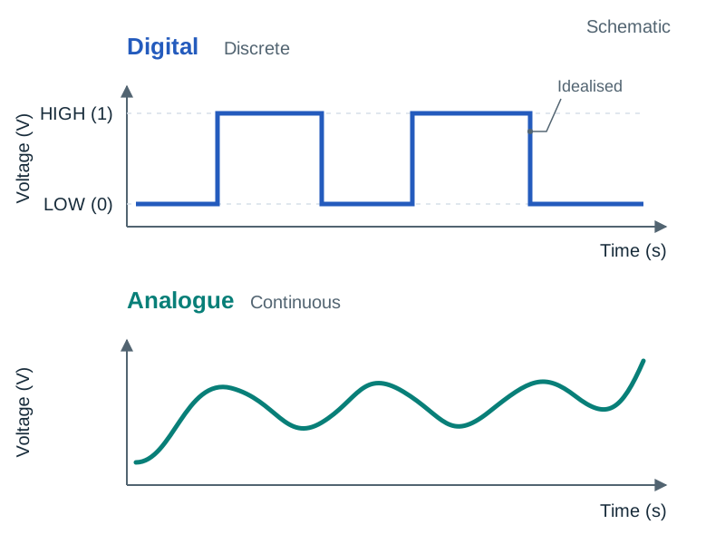
| Feature | Digital Input | Analogue Input |
|---|---|---|
| Signal Nature | Discrete (separate steps, distinct states) | Continuous (smooth, unbroken spectrum) |
| Values Represented | Binary: 0 or 1 (LOW or HIGH) | Theoretically infinite values within an operational range |
| Common Hardware | Push button, toggle switch, magnetic reed switch, PIR motion sensor | Thermistor, Light-Dependent Resistor (LDR), potentiometer, microphone |
| Conversion Needed? | No; read directly by microcontroller logic | Yes; requires an Analogue-to-Digital Converter (ADC) |
When choosing an input for a system design question, use a simple rule of thumb: ask whether the system needs to know yes/no (digital) or how much (analogue).
Discrete and Continuous Data
It is important to distinguish signals from data. While digital and analogue describe electrical signals arriving at a pin, discrete data and continuous data describe values generally:
- Discrete data can only take separate, countable values. Examples include the number of students in a room, shoe sizes, or the count of button presses. Discrete does not mean binary; a count of 27 is discrete because you cannot have 27.4 students.
- Continuous data can take any real value in an unbroken range, limited only by the precision of the measuring instrument. Examples include height, room temperature, time taken to finish a lap, and electrical current.
Once a continuous analogue signal passes through an ADC, the computer stores it as discrete data because only a finite set of whole numbers is available.
Describing the Difference in an Exam Answer
A question asking you to describe the difference between digital and analogue input is one of the most predictable questions on the syllabus. Learning outcome 2.14 uses the verb 'describe', which requires a detailed picture using words or diagrams.
Model Short Answer
"A digital input is discrete: it can only take one of a small number of fixed states, normally two — HIGH (binary 1) or LOW (binary 0). A push button is a digital input because the circuit is either closed or open, with no in-between state, so the microcontroller can read it directly.
An analogue input is continuous: the signal can take any value in an unbroken range and changes smoothly rather than in steps. A light-dependent resistor (LDR) is an analogue input because the voltage it produces varies smoothly with brightness. Because the processor works only in binary, an analogue input must first pass through an analogue-to-digital converter (ADC), which samples the voltage and turns it into a whole number."
In a marking scheme, marks are awarded for four distinct elements: identifying discrete versus continuous; identifying the fixed binary states of a digital input; giving a valid named hardware example of each; and stating that an analogue input requires an analogue-to-digital converter (ADC) while a digital input does not.
Hardware Interfaces and Signal Conversion
Before writing any code, decide what kind of signal the sensor sends: a simple on/off state goes to a digital pin, while a smoothly varying voltage must go to a pin that has an ADC behind it.
A General-Purpose Input/Output (GPIO) digital pin reads binary logic levels. The microcontroller compares the incoming voltage against internal switching thresholds. A voltage close to 0 V registers as logical 0 (LOW), while a voltage close to the supply voltage (typically 3.3 V) registers as logical 1 (HIGH). The processor does not measure intermediate voltages; it simply reports 1 or 0.
An analogue pin routes the incoming continuous voltage into an ADC. On common educational hardware like the BBC micro:bit, pins 0, 1, and 2 can be read either way. The instruction you write in code decides how the hardware behaves: read_digital() reads the pin as a binary 1 or 0, while read_analog() engages the internal ADC and measures the pin as a whole number.
ADC Resolution and Quantisation
The bit depth, or ADC resolution, defines how many discrete numerical steps the converter uses to represent the analogue voltage:
- An 8-bit ADC provides levels (integers 0 to 255).
- A 10-bit ADC provides levels (integers 0 to 1023).
- A 12-bit ADC provides levels (integers 0 to 4095).
A 10-bit ADC returns integers from 0 to 1023, where 0 corresponds to 0 V and 1023 corresponds to the reference voltage (typically 3.3 V). A reading of 0 represents 0 V, while a reading of 511 or 512 represents roughly half of (around 1.65 V). Use maximum reading = 1023 unless an exam question specifies another divisor, and always show your substitution.
The Reading as Binary and Hexadecimal
The ADC does not store decimal numbers internally; it produces a pattern of bits. An 8-bit ADC measuring a light reading of 93 generates the binary byte 01011101 (). In hexadecimal, grouping the bits into nibbles yields 0101 = 5 and 1101 = D, which gives 0x5D. This also explains why an 8-bit ADC has an upper limit of 255: 11111111_2 = 255_{10}.
A digital-to-analogue converter (DAC) performs the exact opposite role: it takes a stored binary number and converts it back into a smooth voltage, such as turning stored audio data into a signal for a speaker.
Sampling Rate and Loss of Accuracy
Resolution and sampling rate are two separate settings, and changing one does not change the other: resolution is about how precisely each reading is recorded, sampling rate about how often readings are taken.
Sampling is the process of taking measurements of a continuous signal at regular, fixed time intervals. The sampling rate (frequency ) is the number of samples captured per second, measured in Hertz (Hz). It is related to the time interval between samples (, in seconds) by:
If a microcontroller samples an analogue sound sensor every 0.001 seconds, the sampling rate is . Over 5 seconds, it gathers .
Why a Digital Recording is an Approximation
A digital representation of an analogue signal is never entirely perfect. It loses accuracy in two distinct ways:
- Quantisation error: The ADC rounds each continuous voltage to the nearest allowable discrete step. With a 10-bit ADC there are 1024 levels. If the actual sensor voltage falls half-way between two levels, it must be rounded. The difference between the actual analogue voltage and the rounded digital value is called quantisation error. Adding more bits creates smaller step sizes and reduces this error.
- Sampling error: Nothing is recorded between consecutive samples. If the analogue signal fluctuates rapidly between two sampling moments, those fluctuations are completely missed. If the sampling rate is too low, the captured data forms a jagged staircase that fails to reflect the original curve.
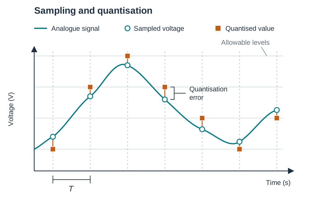
Slowly changing environmental values like room temperature require only a low sampling rate (such as 0.1 Hz, or one sample every 10 seconds), whereas audio signals require tens of thousands of samples per second.
Quick recap — four-line memory rule:
- Digital = states = direct read.
- Analogue = measurement = ADC first.
- Resolution = bits = how precise.
- Sampling rate = Hz = how often.
Reading Inputs and Driving Outputs in MicroPython
An embedded system normally runs a never-ending main loop, and each pass through that loop follows the input–process–output pattern. In Python for microcontrollers (such as MicroPython on the BBC micro:bit), three instructions handle the core hardware interaction:
pin1.read_digital()returns an integer1or0(used for switches, buttons, and digital motion sensors).pin0.read_analog()returns a whole number from0to1023using the internal 10-bit ADC (used for LDRs, thermistors, and potentiometers).pin2.write_digital(1)outputs a HIGH voltage (turning on an LED, buzzer, or relay);pin2.write_digital(0)pulls the pin LOW (turning the device off).
from microbit import *

light_log = []

while True:
    override = pin1.read_digital()      # digital input: 1 or 0
    light = pin0.read_analog()          # analogue input: 0 to 1023
    light_log.append(light)             # store the reading in RAM

    if override == 1:
        pin2.write_digital(0)           # forced OFF
    elif light < 400:
        pin2.write_digital(1)           # dark: turn lamp ON
    else:
        pin2.write_digital(0)           # bright enough: turn lamp OFF

    sleep(1000)                         # pause 1000 ms (1 Hz sampling rate)
Storing Readings Permanently
Appending values to a list (light_log.append(light)) stores data in volatile memory (RAM). When the microcontroller is powered down or reset, that data is wiped out. To store data permanently so it can be analysed in a spreadsheet, write the readings to a file on non-volatile flash storage:
readings = [280, 400, 399, 150, 620]

with open("light_log.csv", "w") as f:
    for i in range(len(readings)):
        f.write(str(i) + "," + str(readings[i]) + "\n")
Using a file ensures that each row records a sample number and its value in comma-separated values (CSV) format. A single variable holds only the current value; a list holds recent data in RAM; a file provides permanent storage.
Designing Automated Embedded Applications
Learning outcome 3.14 expects you to design automated applications using an embedded system. In the written exam, design questions give you a scenario (such as an automated greenhouse or an incubator) and ask you to specify the inputs, processing rules, and outputs.
Example: Automated Greenhouse System
Suppose you are asked to design an embedded system to regulate soil moisture with a manual override switch.
| Stage | Component | Type | Explanation |
|---|---|---|---|
| Input 1 | Soil moisture sensor | Analogue input | The system needs to measure how wet the soil is across a continuous range. |
| Input 2 | Master override switch | Digital input | The system only needs to check whether manual mode is active (open or closed, 1 or 0). |
| Processing | Microcontroller | Central logic | Compares moisture reading to a set threshold. If moisture is below threshold AND override is 0, activate output. |
| Output | Water pump (via relay) | Digital output | A relay acts as an electronic switch to supply power to the pump (1 = ON, 0 = OFF). |
System Block Diagram
A standard system block diagram maps the physical flow of data through the hardware:
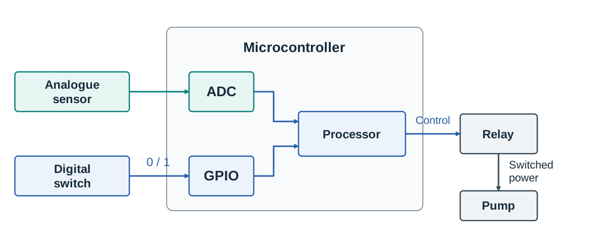
The analogue line must pass through an ADC before entering the microcontroller. The digital switch feeds directly into a GPIO pin because its binary voltage is already compatible with digital processor logic.
Key terms
- Digital Signal
- A discrete electrical signal that can only occupy a fixed set of distinct states, typically binary HIGH (1) or LOW (0).
- Analogue Signal
- A continuous electrical signal that can take any value along an unbroken range.
- Discrete Data
- Data consisting of distinct, separate, countable values with no intermediate values between steps.
- Continuous Data
- Data that can take on any real value within an unbroken numerical interval, limited only by measuring precision.
- Analogue-to-Digital Converter (ADC)
- A hardware component that samples and quantises a continuous analogue voltage into a discrete digital number for a processor.
- Digital-to-Analogue Converter (DAC)
- A hardware component that converts discrete digital values back into a continuous analogue voltage.
- Sampling
- The process of measuring the amplitude of a continuous analogue signal at regular, fixed time intervals.
- Sampling Rate
- The number of discrete samples captured per second from an analogue signal, measured in Hertz (Hz).
- ADC Resolution
- How finely an ADC divides an analogue signal. Quoted either as bit depth n (giving 2^n levels) or as voltage step size (V_ref / maximum reading).
- Quantisation
- The process of rounding an analogue sample value to the nearest discrete numerical level available in the ADC.
- Embedded System
- A dedicated computer system comprising a processor, memory, and peripherals built into a larger device to execute a specific control task.
- Actuator
- An output hardware device, such as a motor, relay, solenoid, or buzzer, that transforms an electrical signal into physical action.
- Calibration
- The process of mapping raw sensor readings or voltages to actual physical units such as degrees Celsius or lux.
Check yourself
What is the primary difference between a digital input and an analogue input?
A digital input is discrete, taking only one of a fixed set of states (usually HIGH or LOW, 1 or 0), while an analogue input is continuous and can take any value along an unbroken range.
Why does an analogue input require an Analogue-to-Digital Converter (ADC) before the microcontroller can use it?
The sensor generates a continuous analogue voltage, but computer processors contain digital logic gates that can only store and manipulate discrete binary numbers.
Classify the following as discrete or continuous data: (a) the number of cars passing a sensor in an hour, (b) the air pressure in a tyre.
(a) Discrete, because cars are counted in distinct whole numbers. (b) Continuous, because pressure varies smoothly across an unbroken physical range.
A 10-bit ADC operates with a reference voltage of 3.3 V. What raw reading corresponds to 0 V, and approximately what reading corresponds to 1.65 V?
A reading of 0 corresponds to 0 V. Half of the full voltage range (1.65 V) corresponds to approximately half of the maximum reading of 1023, which is 511 or 512.
An 8-bit ADC produces a raw integer reading of 93. Express this value in binary and hexadecimal.
In 8-bit binary, 93 is 01011101 (64 + 16 + 8 + 4 + 1). In hexadecimal, grouping the nibbles (0101 and 1101) gives 5D.
State the four-line memory rule for inputs, conversion, resolution, and sampling.
Digital = states = direct read. Analogue = measurement = ADC first. Resolution = bits = how precise. Sampling rate = Hz = how often.