
Mechanisms transfer and control movement, force, and energy to make machines work efficiently. In the Junior Cycle examination, you will identify types of motion, calculate gear and pulley ratios, determine linear travel time, and justify mechanism choices for practical designs.
The Four Types of Motion
Motion in mechanisms follows four pathways:
| Motion | Pathway | Everyday Example |
|---|---|---|
| Rotary | Continuous turning in a circular path around an axle | Electric motor shaft |
| Linear | Movement along a straight line in one direction | Lift carriage |
| Reciprocating | Continuous back-and-forth movement in a straight line | Sewing machine needle |
| Oscillating | Continuous back-and-forth swinging along a curved arc | Pendulum clock |
Exam questions regularly ask you to identify the input and output motion of a device. Make sure you distinguish reciprocating motion along a straight line from oscillating motion along a curved arc.
Mechanisms That Change Motion
Machines use mechanical components to redirect force and convert motion between parts:
| Mechanism | Motion Conversion | Application |
|---|---|---|
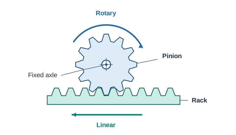
| Rack and pinion | Rotary to linear (or linear to rotary) | Car steering, greenhouse vents |
| Crank and slider | Rotary to reciprocating | Engine pistons |
| Cam and follower | Rotary to reciprocating (cam lifts follower; gravity or spring returns it) | Engine valve control |
| Bell crank lever | Redirects movement and force through 90° | Bicycle brakes |
| Universal joint | Transmits rotary motion between shafts at an angle | Drive shafts, steering columns |
| Chain and sprocket | Transmits rotary motion between shafts without slip | Bicycle drive |
A belt drive transfers rotary motion with smooth friction, which can slip to protect a motor if a mechanism jams.
Gears, Pulleys, and Velocity Ratios
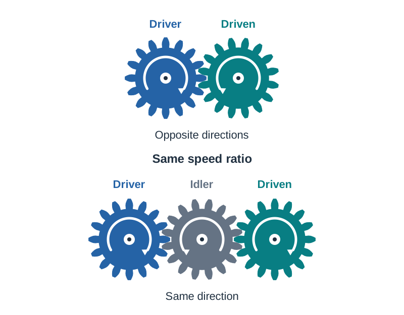
The driver gear is turned by the input motor, while the driven gear receives power and turns the output shaft. Directly meshing external gears rotate in opposite directions. Placing an idler gear between them makes the driver and driven gears turn in the same direction without changing the speed ratio.
Velocity ratio (VR) has no units:
- VR = teeth on driven gear ÷ teeth on driver gear = diameter of driven pulley ÷ diameter of driver pulley (assuming no belt slip).
- Output speed = input speed ÷ VR. Slower output speed delivers greater turning force (torque).
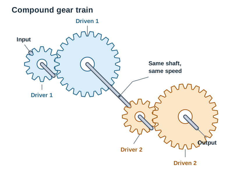
- Compound gear train: VR = (driven 1 ÷ driver 1) × (driven 2 ÷ driver 2).
RPM means revolutions per minute.
Travel Calculations, Testing, and Efficiency
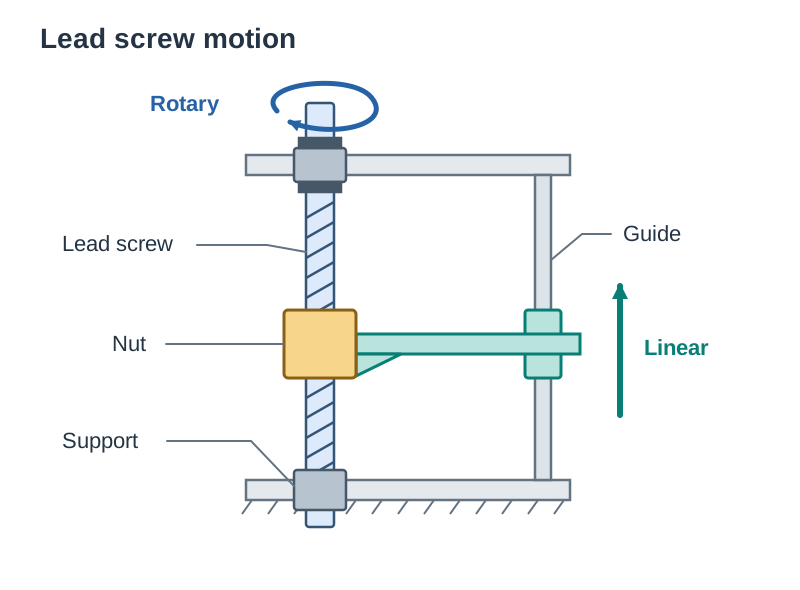
A lead screw converts rotary motion into linear motion. One pinion revolution moves the rack by the same number of teeth as the pinion has:
- Total distance = revolutions × distance per revolution.
- Revolutions needed = total distance ÷ distance per revolution.
- Time taken = revolutions × time per revolution. At a speed given in RPM, one revolution takes 60 ÷ RPM seconds.
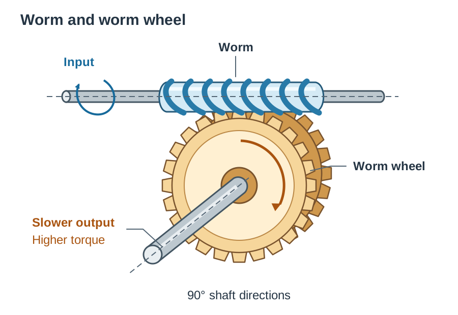
A worm and worm wheel gives a large speed reduction and high torque through 90°. Some worm drives and lead screws are self-locking, meaning the load cannot drive them backwards.
A Nyloc nut is a lock nut whose nylon insert resists loosening. Leave clearance so the wheel rotates freely.
Friction wastes input energy as heat, reducing mechanical efficiency. Correct shaft alignment and lubrication reduce friction and wear. When prototyping, test physical models or computer simulations to evaluate motion and refine gear ratios before final making.
Key terms
- Rotary motion
- Continuous movement in a circular path around a central axle.
- Linear motion
- Movement along a straight line in one direction.
- Reciprocating motion
- Continuous back-and-forth movement along a straight line.
- Oscillating motion
- Continuous back-and-forth swinging movement along a curved arc.
- Velocity Ratio (VR)
- The ratio of driven gear teeth (or diameter) to driver gear teeth (or diameter), showing how much a drive changes speed and torque.
- Idler gear
- An extra gear placed between driver and driven gears that makes both turn in the same direction without changing the velocity ratio.
- Rack and pinion
- A mechanism pairing a circular gear with a flat toothed rail that converts rotary motion into linear motion.
- Universal joint
- A mechanical coupling that transmits rotary motion between two shafts positioned at an angle to each other.
Check yourself
What type of motion does a swinging pendulum clock demonstrate?
Oscillating motion.
Which mechanism turns rotary motion into linear motion using a circular gear and a flat toothed bar?
A rack and pinion.
If a 20 mm driver pulley running at 60 RPM drives a 60 mm driven pulley, what is the output speed?
20 RPM (VR = 60 ÷ 20 = 3; output speed = 60 RPM ÷ 3 = 20 RPM).
A 10-tooth pinion running at 5 RPM moves a rack. How long does it take to move 10 teeth on the rack?
12 seconds (moving 10 teeth requires 1 revolution; at 5 RPM, 1 revolution takes 60 ÷ 5 = 12 seconds).
Why is a Nyloc nut used to secure a wheel on an axle?
Its nylon insert resists loosening, while leaving clearance allows the wheel to rotate freely.