
A control system uses inputs, processing, and outputs to make a device behave in a specific way. The exam focuses on classifying components, completing truth tables, and designing logic control circuits.
The Input-Process-Output Model
A controlled system uses components to achieve a defined function. Switches and sensors supply input signals.
| Stage | Function | Examples |
|---|---|---|
| Input | Gathers environmental data or user commands | Push-to-make (PTM) switch, toggle switch, light-dependent resistor (LDR), thermistor |
| Process | Makes decisions and controls current flow | Logic gates, microchips, transistor |
| Output | Converts electrical energy into physical action or signals | DC motor, buzzer, lamp, LED, solenoid |
- Transistor: electronic switch where a small signal controls a larger current.
- Limit switch: input sensor detecting travel limits to stop a motor.
Logic Gates and Truth Tables
Digital circuits use binary signals: 1 (high/on) or 0 (low/off). Logic gates process these signals by set rules.
- AND gate: Output is 1 only when all inputs are 1.
- OR gate: Output is 1 when at least one input is 1.
- NOT gate: Inverts single input (0 to 1, 1 to 0); drawn as a triangle with an inverting circle.
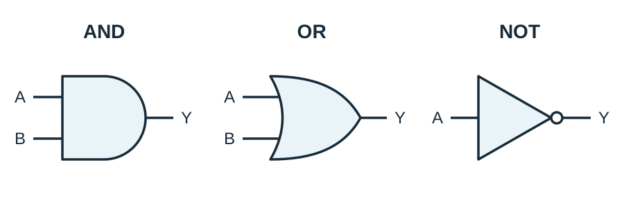
A truth table shows every input combination and resulting output:
| Input A | Input B | AND Output | OR Output |
|---|---|---|---|
| 0 | 0 | 0 | 0 |
| 0 | 1 | 0 | 1 |
| 1 | 0 | 0 | 1 |
| 1 | 1 | 1 | 1 |
Combining Logic and Motor Control
Control circuits combine gates to operate actuators safely:
- 'Both' requires an AND gate.
- 'Either' requires an OR gate.
- A NOT gate inverts a signal (e.g. converting 1 to 0 to halt a motor).
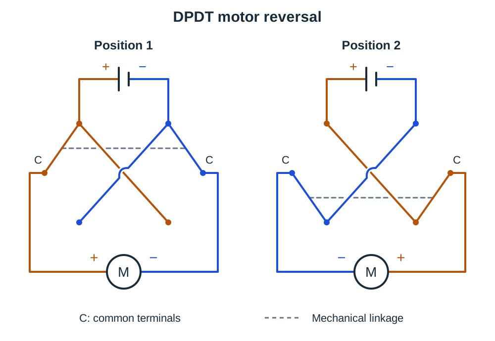
To reverse a DC motor, swap supply polarity. Connect the motor to DPDT common terminals and power across switched contacts with opposite polarity.
Control Sequences, Simulation, and Safe Testing
Microcontrollers execute instructions in a fixed order, branching on conditions:
- Read sensor (temperature).
- Is temperature too high? Yes: turn fan ON; No: turn fan OFF.
- Loop back to step 1.
Simulation models a circuit mechanically, electrically, or digitally to test logic states before physical assembly.
Disconnect power before changing wiring and check component ratings. Document progression by recording initial designs, test results, modifications, and retests.
Key terms
- Controlled system
- A system using components to modify behaviour to achieve a defined function.
- Actuator
- An output device that converts electrical energy into physical movement.
- Limit switch
- An input switch that detects end of travel to halt motor motion.
- Transistor
- An electronic switch where a small input signal controls a larger current.
- Truth table
- A table showing all binary input combinations and resulting outputs.
- Simulation
- The imitation of a situation or process through mechanical, electrical, or digital modelling.
- DPDT switch
- A double-pole double-throw switch that reverses DC motor rotation by swapping polarity.
Check yourself
What is the output of an AND gate when inputs are 1 and 0?
0; an AND gate outputs 1 only if both inputs are 1.
Why is a limit switch used on an automated gate?
It detects travel limits to stop the motor and prevent damage.
How does a DPDT switch reverse a DC motor?
Connect motor to common terminals and swap supply polarity across switch contacts.
Why simulate a control circuit before building it?
To test logic behaviour and fix errors before physical assembly.