Resonance
Resonance occurs when a system is made to vibrate at its natural frequency by a periodic driving force of the same frequency (). Energy is transferred efficiently into the system, resulting in a large amplitude of vibration.
Every elastic mechanical system has one or more natural frequencies at which it tends to vibrate freely when disturbed.
Demonstrating Resonance
Mount two identical tuning forks of the same frequency on hollow resonance boxes placed open-end to open-end. Strike the first fork, then silence its prongs by hand. The second fork continues sounding audibly because sound waves transferred energy to it at its exact natural frequency. If plasticine is attached to one fork to alter its frequency, the resonance stops immediately.
Similarly, holding a sounding tuning fork over a tube open at the top and closed by water at the bottom gives a loud resonance when the air column length is about a quarter wavelength ().
Resonance in Everyday Life
- Pushing a swing: Pushing a swing with small pushes timed to its natural swing period transfers energy efficiently, driving it to a large amplitude.
- Acoustic instruments: The wooden body of a violin or acoustic guitar resonates with vibrating strings, coupling energy to the air to produce a much louder sound.
- Radio tuning: Adjusting the tuning dial matches the natural frequency of an internal electrical circuit to the radio carrier frequency, amplifying only that station.
- Vibration damage: Car body panels rattle loudly at specific engine speeds when matching frequencies align.
- Bridge oscillations: London's Millennium Bridge (2000) swayed excessively when the sideways rhythm of pedestrians' footsteps matched a natural swaying frequency of the span. Mechanical dampers were installed to absorb and dissipate the vibrational energy.
The Doppler Effect
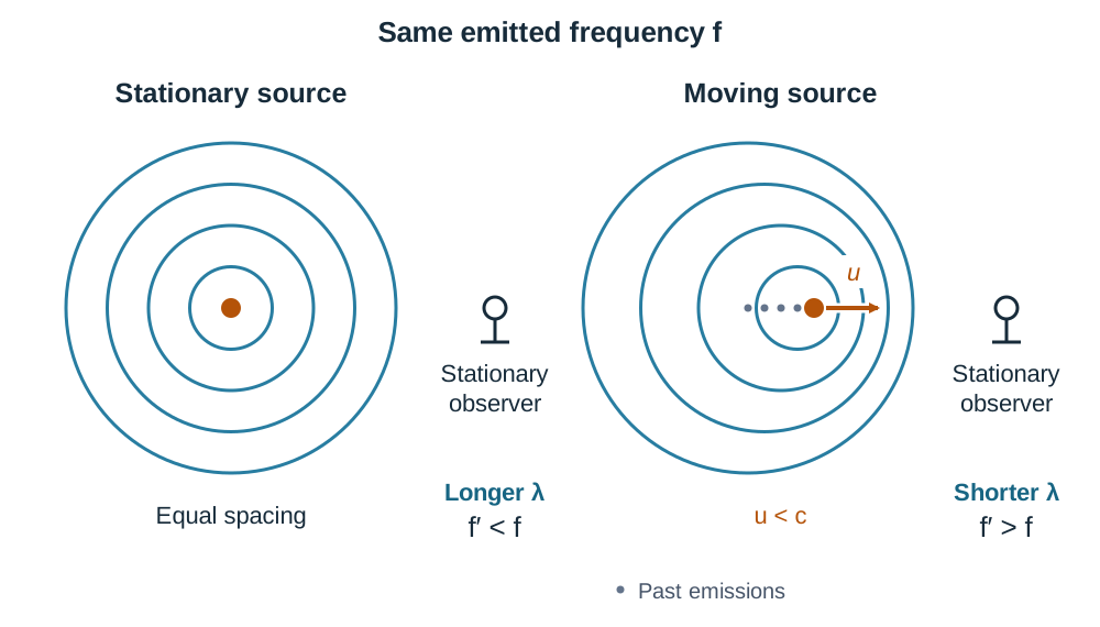
The Doppler effect is the apparent change in the frequency (or wavelength) of a wave observed when there is relative motion between the source of the waves and the observer.
Wavefront Model
- When a wave source is stationary, wavefronts spread outwards as evenly spaced concentric circles.
- When the source moves forward at speed , it chases the wavefronts it emits. Ahead of the moving source, successive wavefronts are crowded closer together, producing a shorter observed wavelength and a higher observed frequency (, heard as a higher pitch).
- Behind the moving source, wavefronts are left further apart, producing a longer observed wavelength and a lower observed frequency (, heard as a lower pitch).
Formula and Calculation Strategy
For a stationary observer and a moving source:
where is the emitted frequency, is the wave speed in the medium ( for sound in air), and is the source speed. The official specification writes μ in place of u in this Doppler formula: here μ means source speed in m s⁻¹, not the mass per unit length used in the stretched-string formula.
- Source approaching: Use the minus sign: . The smaller denominator increases above .
- Source receding: Use the plus sign: . The larger denominator decreases below .
Applications
- Radar speed guns: Microwaves are directed at a moving car. The Doppler shift in the frequency of the reflected microwave signal allows the vehicle's speed to be calculated. (Note: Handheld laser guns / LIDAR measure the time of flight of light pulses rather than the Doppler shift).
- Medical Doppler ultrasound: High-frequency sound waves reflect off moving red blood cells. The measured Doppler frequency shift maps the speed and direction of blood flow through heart valves and arteries.
- Astronomy (Red Shift): Light emitted by distant galaxies shows spectral lines shifted towards longer wavelengths (lower frequencies). This red shift indicates that galaxies are receding from Earth, providing core evidence that the universe is expanding.
The Wave Nature of Light and Young's Slits
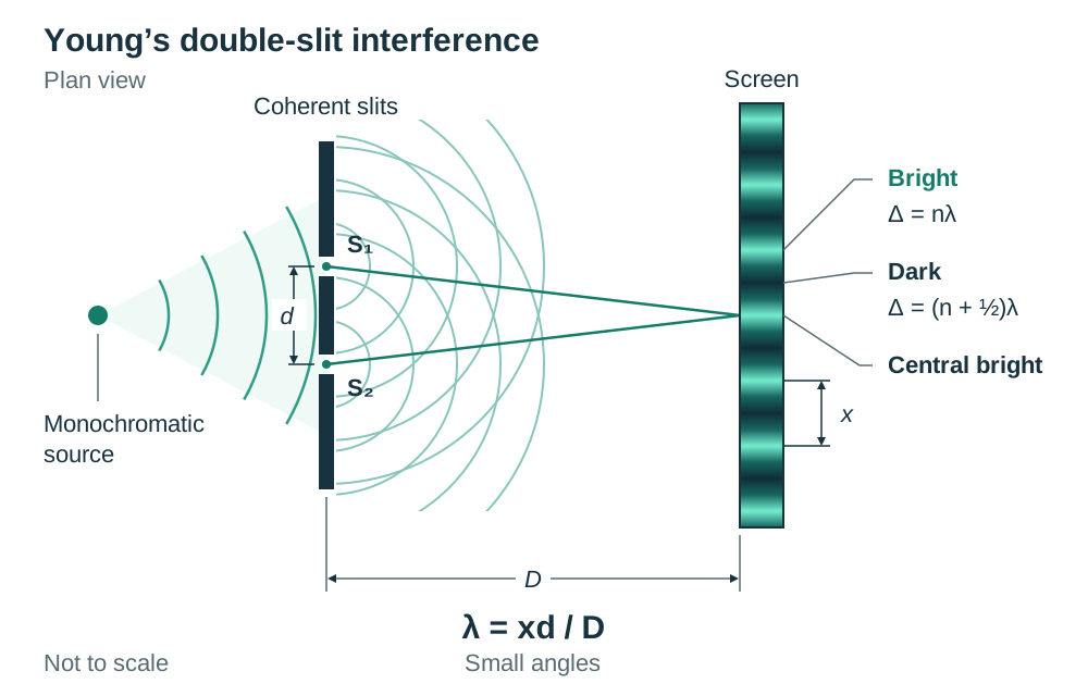
For centuries, debate persisted over whether light was a stream of particles or a wave. While reflection and refraction can be described with geometric rays, diffraction and interference prove decisively that light travels as a wave. Diffraction is the spreading of a wave as it passes through a gap or around an obstacle. Diffraction is most noticeable when the gap or obstacle is about the same size as the wavelength of the wave. Visible light has tiny wavelengths between 400 nm and 700 nm, so it casts sharp shadows and does not bend noticeably around everyday openings like open doors. In contrast, audible sound waves have wavelengths of the order of metres, so they diffract easily around doorway edges. In 1801, Thomas Young showed that light is a wave by passing it through two narrow slits and observing an interference pattern. Light from a single monochromatic source illuminates two closely spaced parallel slits. These slits act as coherent sources, meaning they have the same frequency and maintain a constant phase difference. Where the waves from the two slits overlap they add together (superposition), giving an interference pattern of bright and dark fringes on a screen. Constructive interference occurs where waves arrive in phase (crest meets crest), producing bright fringes. The path difference must equal a whole number of wavelengths: Path Difference = nλ (where n = 0, 1, 2, ...). Destructive interference occurs where waves arrive exactly out of phase (crest meets trough), producing dark fringes. The path difference equals an odd number of half-wavelengths: Path Difference = (n + 1/2)λ. For small angles at distance D from the slits, where slit spacing is d and adjacent fringe separation is x, the fringe formula is λ = xd / D. Note: if a problem gives the distance across a set of bright fringes, remember that 13 bright fringes span 12 fringe intervals.
The Diffraction Grating and Experimental Investigation
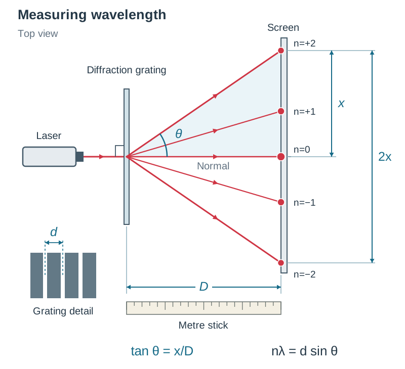
A diffraction grating consists of a transparent plate engraved with an enormous number of parallel, equally spaced lines, typically 300 to 600 lines per millimetre. A grating is vastly superior to double slits for measuring wavelength because having thousands of slits produces interference maxima that are far brighter, sharper, and spaced much further apart, drastically reducing experimental error. The distance between the centres of adjacent slits is the grating constant (d). If a grating has N lines per millimetre, convert to lines per metre by multiplying by 1000, then invert: d = 1 / (N × 1000) metres. When parallel monochromatic light strikes the grating normally, constructive interference occurs at angles θ according to: nλ = d sin θ, where n is the diffraction order (n = 0 for the central image, n = 1 for the first order, and so on). Because sin θ cannot exceed 1, the highest order that can be seen is the largest whole number less than d / λ. If d / λ evaluates to an exact integer, that order would lie at 90° along the plane of the grating and cannot reach a screen. The total number of bright images observable is 2n_max + 1, accounting for symmetrical orders on both sides plus the central zero-order maximum. ### Experimental Measurement of the Wavelength of Light. Apparatus: monochromatic light source (laser; note: a sodium vapour lamp requires a spectrometer to measure diffraction angles directly rather than projecting onto a screen), diffraction grating mounted perpendicular to the beam, screen, and metre stick. Method: 1. Set up the laser so the beam strikes the grating at right angles to its surface (along the normal). 2. On a screen placed at a distance D behind the grating, observe the bright diffraction spots. 3. For order n = 1 and n = 2, measure the total distance 2x between the corresponding bright spots on opposite sides of the central axis, and divide by 2 to get x. 4. Calculate the diffraction angle using tan θ = x / D. Calculation: Calculate d = 1 / (N × 10³). Substitute n, d, and θ into λ = (d sin θ) / n, and average the calculated wavelengths. Sources of error: judging the exact centre of diffracted spots; measuring small values of x or D with a metre stick; the grating not being set exactly perpendicular to the incident beam. Safety precaution: never look directly into a laser beam or its specular reflection; keep the beam aligned at bench height below eye level.
Polarisation as Proof of Transverse Waves
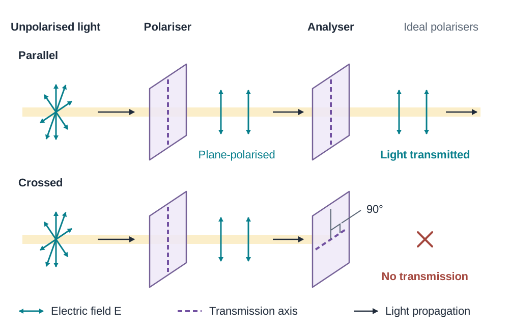
Polarisation is the restriction of the vibrations of a transverse wave to one plane. In unpolarised light, the electric field oscillates in all possible planes perpendicular to the direction of propagation. When light passes through a polarising filter (such as a Polaroid sheet), the filter transmits only the wave component vibrating parallel to its transmission axis, producing plane-polarised light. A three-step demonstration proves this behaviour: 1. Look at a light source through two Polaroid sheets held with their transmission axes parallel; light passes through clearly. 2. Slowly rotate one Polaroid (the analyser) relative to the other. The transmitted intensity steadily diminishes. 3. When the analyser has rotated through 90° (crossed polaroids), the light completely extinguishes. Rotating by another 90° restores transmission. Longitudinal waves, like sound, oscillate exclusively parallel to the direction of energy transfer and therefore cannot be polarised. The fact that light can be polarised proves that light is a transverse wave. Practical application: light reflected from non-metallic surfaces like glass, water, or wet asphalt becomes partially plane-polarised in the horizontal plane. Polaroid sunglasses have vertical transmission axes, so they block most of the horizontally polarised glare from water and wet roads while letting through about half of the ordinary unpolarised daylight.
Dispersion: Prisms versus Diffraction Gratings
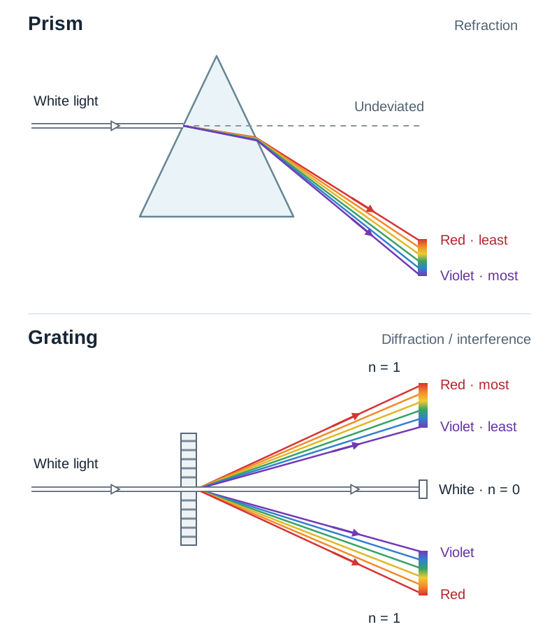
Dispersion is the separation of composite light (such as white light) into its constituent colours or wavelengths. White light comprises visible wavelengths from approximately 400 nm (violet) to 700 nm (red). Dispersion can be produced using either a triangular glass prism or a diffraction grating, but the underlying physics differs completely. In a glass prism, dispersion occurs by refraction. The refractive index of glass varies with wavelength: shorter wavelengths experience a higher refractive index and slow down more in the glass. Violet light has the shortest wavelength, slows down the most, and undergoes the greatest deviation. Red light has the longest wavelength, slows down least, and refracts least. A prism produces a single continuous spectrum with red bent least and violet bent most. In a diffraction grating, dispersion occurs by interference and diffraction. From nλ = d sin θ, for a given order n, sin θ is proportional to λ. Red light has a longer wavelength than violet light, so sin θ (and therefore angle θ) is larger for red light. In every non-zero diffraction order, red light deviates most and violet light deviates least. The central zero-order image (n = 0) has zero path difference for all wavelengths, so all colours arrive in phase at the centre to form an undispersed white line. Diagram comparison: for a prism, sketch an incoming white ray bending towards the base, spreading with red at the top (least deflected) and violet at the bottom (most deflected). For a grating, sketch a normal incident beam emerging as a central white line (n = 0), flanked symmetrically by first-order spectra (n = 1) where violet is closest to the centre and red is furthest away.